PQRCHCA0Q - Remote control LG - Free user manual and instructions
Find the device manual for free PQRCHCA0Q LG in PDF.
| Product Type | Wired remote control for air conditioner |
| Brand | LG |
| Compatible Models | PQRCHCAOQ, PQRCHCAOQW |
| Dimensions (approx.) | 120 x 80 x 20 mm |
| Weight (approx.) | 200 g |
| Power Supply | Via connection cable from indoor unit |
| Supplied cable length | 10 m |
| Main Functions | Cooling, Heating, Auto, Dehumidification, Ventilation |
| Temperature Setting | Cooling: 18-30 °C, Heating: 16-30 °C |
| Fan Speed | Low, Medium, High, Very High (depending on mode) |
| Additional Functions | Parental control, Ambient temperature display, Remote lock |
| Installation Configuration | Operation test, Central address, PSE, Thermistor, Ceiling height, Static pressure, Master/Slave, Celsius/Fahrenheit |
| Group Control | Up to multiple indoor units or multiple remote controls |
| Maintenance and Cleaning | Clean with a soft dry cloth; do not use solvents |
| Safety | Installation by qualified professional; do not expose to water; do not disassemble |
| Spare parts / Repairability | Connection cable (ref. provided), mounting screws; repair by authorized center |
| General Information | Multilingual manual (FR, DE, EN, ES, IT, PT, RU, etc.); 128 pages |
Frequently Asked Questions - PQRCHCA0Q LG
User questions about PQRCHCA0Q LG
0 question about this device. Answer the ones you know or ask your own.
Ask a new question about this device
Download the instructions for your Remote control in PDF format for free! Find your manual PQRCHCA0Q - LG and take your electronic device back in hand. On this page are published all the documents necessary for the use of your device. PQRCHCA0Q by LG.
USER MANUAL PQRCHCA0Q LG
Please read this manual carefully before operating your set and retain it for future reference.
MODELS:PQRCHCAOQ
PQRCHCAOQW
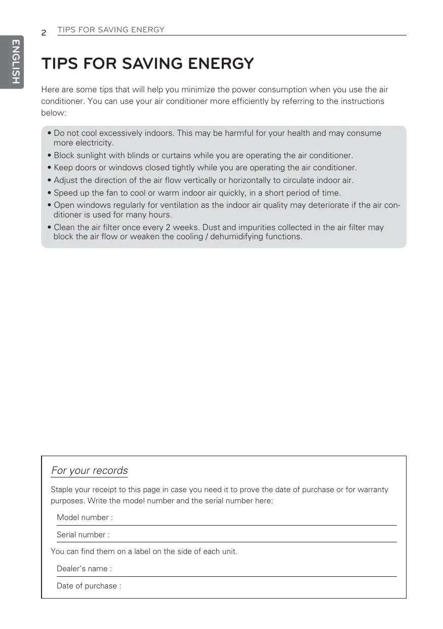
TIPS FOR SAVING ENERGY
Here are some tips that will help you minimize the power consumption when you use the air conditioner. You can use your air conditioner more efficiently by referring to the instructions below:
- Do not cool excessively indoors. This may be harmful for your health and may consume more electricity.
- Block sunlight with blinds or curtains while you are operating the air conditioner.
- Keep doors or windows closed tightly while you are operating the air conditioner.
- Adjust the direction of the air flow vertically or horizontally to circulate indoor air.
- Speed up the fan to cool or warm indoor air quickly, in a short period of time.
- Open windows regularly for ventilation as the indoor air quality may deteriorate if the air conditioner is used for many hours.
- Clean the air filter once every 2 weeks. Dust and impurities collected in the air filter may block the air flow or weaken the cooling / dehumidifying functions.
For your records
Staple your receipt to this page in case you need it to prove the date of purchase or for warranty purposes. Write the model number and the serial number here:
Model number :
Serial number :
You can find them on a label on the side of each unit.
Dealer's name :
Date of purchase :
IMPORTANT SAFETY INSTRUCTIONS
READ ALL INSTRUCTIONS BEFORE USING THE APPLIANCE.
Always comply with the following precautions to avoid dangerous situations and ensure peak performance of your product
WARNING
It can result in serious injury or death when the directions are ignored
CAUTION
It can result in minor injury or product damage when the directions are ignored
WARNING
- Installation or repairs made by unqualified persons can result in hazards to you and others.
- Installation MUST conform with local building codes or, in the absence of local codes, with the Nation Electrical Code NFPA 70/ANSI C1-1003 or current edition and Canadian Electrical Code Part1 CSA C.22.1.
- The information contained in the manual is intended for use by a qualified service technician familiar with safety procedures and equipped with the proper tools and test instruments.
- Failure to carefully read and follow all instructions in this manual can result in equipment malfunction, property damage, personal injury and/or death.
Installation
- Be sure to request to the service center or installation specialty store when installing products.
- It will cause fire or electric shock or explosion or injury.
-
Request to the service center or installation specialty store when reinstalling the installed product.
-
It will cause fire or electric shock or explosion or injury.
-
Do not disassemble, fix, and modify products randomly.
- It will cause fire or electric shock.
Operation
- Do not place flammable stuffs close to the product.
- It will cause fire.
- Do not allow water to run into the product.
- It will cause electric shock or breakdown.
- Do not give the shock to the product.
- It will cause breakdown when giving the shock to the product.
- Request to the service center or installation specialty store when the product becomes wet.
- It will cause fire or electric shock.
- Do not give the shock using sharp and pointed objects.
- It will cause breakdown by damaging part.

CAUTION
- Do not clean using the powerful detergent like solvent but use soft cloths.
- It will cause fire or product deformation.
- Do not press the screen using powerful pressure or select two buttons. - It will cause product breakdown or malfunction.
- Do not touch or pull the lead wire with wet hands. - It will cause product breakdown or electric shock.
TABLE OF CONTENTS
2 TIPS FOR SAVING ENERGY
3 IMPORTANT SAFETY INSTRUCTIONS
6 PART DESCRIPTION
6 Using the remote control
6 Accessory
7 INSTALLATION IN-STRUCTION
8 Group Control
9 Install Setting
9 - How to enter installer setting mode
10 - Installer Setting Code Table
11 - Test Run Mode
11 - Setting Address of Central control
12 -E.S.P
12 -Thermistor
13 - Ceiling Height Selection
13 -Static Pressure Setting
14 -Remote Controller Master/Slave Setting
14 -Fahrenheit Switching
15 OWNER'S INSTRUCTION
15 Standard Operation
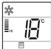
15 -Cooling Mode
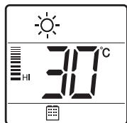
15 - Heating Mode
15 - Auto Operation Mode
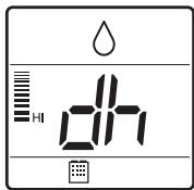
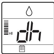
15 - Dehumidification Mode
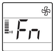
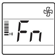
15 -Fan Mode
16 Function setting
16 - Fan Speed Selection
16 - Room Temperature Check
16 -Child Lock
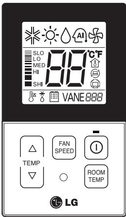
PART DESCRIPTION
Using the remote control
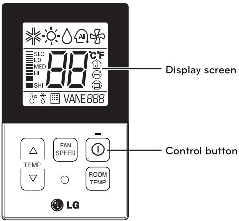
| Control panel | Display screen | Description |
| TEMP | 18~30°C | Temperature adjustment button: Adjusts the room temperature when cooling and heating. |
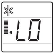
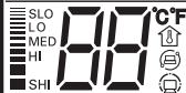
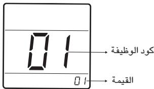
| FAN SPEED | LDO LDO MDO MISO SHI | Indoor fan speed button: Adjusts the fan speed. |
| ① | On/Off button: Turns the power on/off. | |
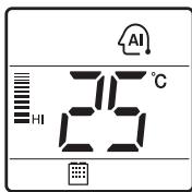
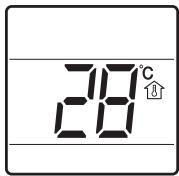
| ROOM TEMP | Displays the room temperature. Ex 23° |
Accessory
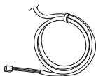
Connection Cable (1EA, 10m)

Screw (2 EA)
Owner's / Installation manual
INSTALLATION INSTRUCTION
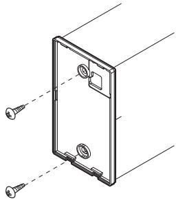
1 Please fix tightly using provided screw after placing remote controller setup board on the place where you like to setup.
- Please set it up not to bend because poor setup could take place if setup board bends.
Please set up remote controller board fit to the reclamation box if there is a reclamation box.
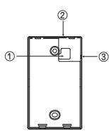
2 Can set up Wired remote controller cable into three directions.
- Setup direction: the surface of wall reclamation, upper, right
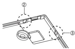
- If setting up remote controller cable into upper and right side, please set up after removing remote controller cable guide groove.
* Remove guide groove with long nose.
① Reclamation to the surface of the wall
② Upper part guide groove
③ Right part guide groove
3 Please connect indoor unit and remote controller using connection cable.
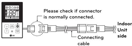
4 Please use extension cable if the distance between wired remote controller and indoor unit is more than 10m
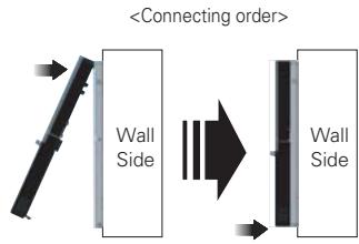
5 Please fix remote controller upper part into the setup board attached to the surface of the wall, as the picture below, and then, connecta with setup board by pressing lower part.
- Please connect not to make a gap at the remote controller and setup board's upper and lower, right and left part.
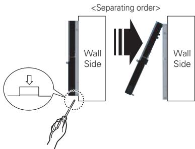
When separating remote controller from setup board, as the picture below, after inserting into the lower separating hole using screw driver and then, spinning clockwise, remote controller is separated.
- There are two separating holes. Please individually separate one at a time.
- Please be careful not to damage the inside components when separating.
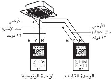
Group Control
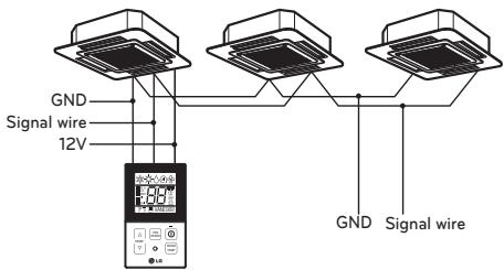
1 When installing more than 2 units of air conditioner to one wired remote controller, please connect as the right figure.
- If it is not event communication indoor unit, set the unit as slave.
- Check for event communication through the product manual.
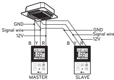
2 When installing more than 2 wired remote controllers to one air conditioner, please connect as the right picture.
- When installing more than 2 units of wired remote controller to one air conditioner, set one wired remote controller as master and the others all as slaves, as shown in the right picture.
- You cannot control the group as shown in the right for some products.
- Refer to the product manual for more detail. When controlling multiple indoor units with event communication function with one remote controller, you must change the master/slave setting from the indoor unit.
- For ceiling type cassette and duct product group, change the switch setting of the indoor PCB.
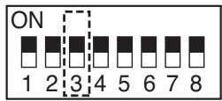
3 switch OFF: Master (Factory default setting)
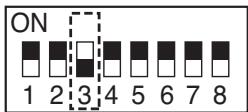
3 switch ON: Slave
- For wall-mount type and stand type product, change the master/slave setting with the wireless remote controller. (Refer to wireless remote controller manual for detail)
- When installing 2 remote controllers to one indoor unit with event communication function, set the master/slave of the remote controller. (Refer to remote controller master/slave selection)
When controlling the group, some functions excluding basic operation setting, fan level
Min/Mid/Max, remote controller lock setting and time setting may be limited.
3 When installing more than 2 wired remote controllers to one air conditioner, please connect as the right picture.
- When installing more than 2 units of wired remote controller to one air conditioner, set one wired remote controller as master and the others all as slaves, as shown in the right picture.
- You cannot control the group as shown in the right for some products.
-
Refer to the product manual for more detail.
-
When controlling in groups, set the master/slaver of the remote controller. Refer to Installer setting section on how to set master/slave for more detail.
Install Setting
How to enter installer setting mode

CAUTION
- Installer setting mode is to set the detail function of the remote controller. If the installer setting mode is not set correctly, it can cause problems to the product, user injury or property damage. This must be set by an certificated installer, and any installation or change that is carried out by a non-certificated person should be responsible for the results. In this case, free service cannot be provided.
1 If you want to set installer setting mode, Press the Temperature up button and the Room Temp button same time for five seconds.
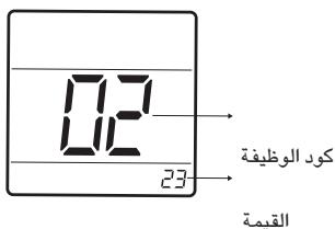
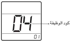
2 When you enter the setting mode Initially. Function code is displayed on the LCD screen.
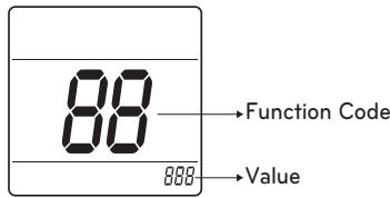
- Some categories of the menu may not be displayed according to the function of the product, or the menu name may be different.
1 General air-conditioner product
| No. | Function | Code | Value |
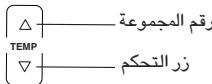
| 1 | Test Run | 01 | 01:Set |
| 2 | Address Setting | 02 | 00~FF : Address |
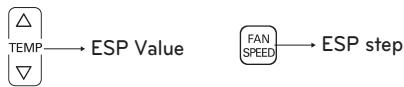
| 3 | E.S.P. Value | 03 | <ESP Step> 01:VeryLow 0 ~ 255 030 ! 000 02:Low 03:Med Function Code ESP step ESP value 04:High 05:Very High |
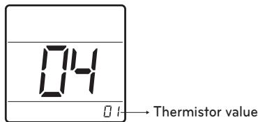
| 4 | Thermistor | 04 | 01:Remo 02:Indoor 03:2TH |
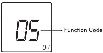
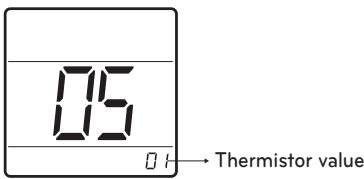
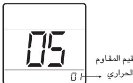
| 5 | Ceiling Height | 05 | 01:Med 02:Low 03:High 04:Very High |
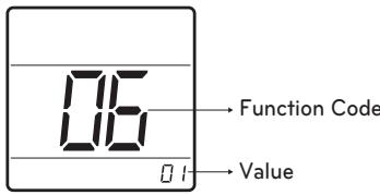
| 6 | Static Pressure | 06 | 01:V-H 02:F-H 03:V-L 04:F-L |
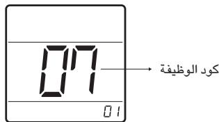
| 7 | Master Setting | 07 | 00:Slave 01:Master |
| 8 | Celsius Fahrenheit Switching | 12 | 00:Celsius (Optimized only for U.S.A) 01:Fahrenheit |
- Some contents may not be displayed depending on the product function
Test Run Mode
After installing the product, you must a test Run Mode. For details related to the Product manual.
1 Press button and button Simultaneously for more than 3 seconds.
2 Setup figure '01' blinks
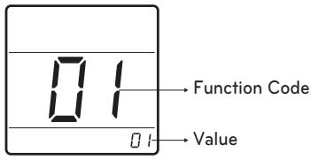
3 Press 0 button to start.
4 During the test run, pressing the below button will exit run.
Setting Address of Central control
It's the functional to use connecting central control.
1 Press button and button Simultaneously for more than 3 seconds.
2 Setup function code '02' pressing by button.
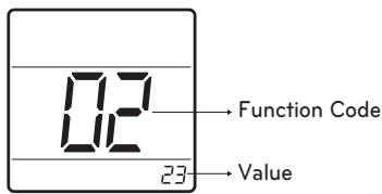
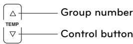
3 Set group number and indoor number.
4 Press 0 button to save.
5 Press button and button Simultaneously for more than 3 seconds After the setting has been completed.
NOTE
- After setup, it automatically gets out of setup mode if there is no button input for 25seconds.
- When existing without pressing set button, the manipulated isn't reflected.
E.S.P
This is the functional that decides the strength of the wind for each wind level and because this function is to make the installation easier.
- If you set ESP incorrectly, the air conditional may malfunction.
- This setting must be carried out by a certificated-thecnition.
1 Press button and button Simultaneously for more than 3 seconds.
2 Setup function code '03' pressing by ROOM TEMP button.
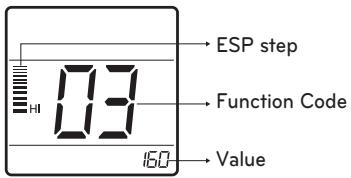
3 Select ESP fan step and ESP value.
- ESP value range : 0~255
4 Press 0 button to save.
5 Press button and button Simultaneously for more than 3 seconds After the setting has been completed.
!NOTE
- When setting ESP value on the product without very weak wind or power wind function, it may not work.
- Please be careful not to change the ESP value for each fan step.
- It does not work to setup ESP value for very low/power step for some product.
- ESP value is available for specific range belongs to the product.
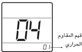
Thermistor
This is the function to select the temperature sensor to judge the room temperature.
1 Press button and button Simultaneously for more than 3 seconds.
2 Setup function code '04' pressing by ROOM TEMP button.
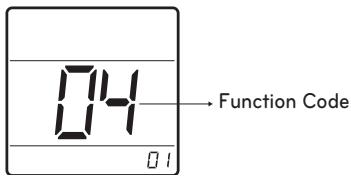
3 Set Thermistor value by pressing button by pressing temperature button. (01: Remote Controller, 02: Indoor, 03: 2TH)
4 Press 0 button to save.
5 Press button and button Simultaneously for more than 3 seconds After the setting has been completed.
NOTE
The function of 2TH has difference operation characteristics according to product.
- Cooling: Operation of higher temperature by comparing indoor unit's and wired remote controller's temperature. (there are products that operate at a lower temperature.)
- Heating: Operation of lower temperature by comparing indoor unit's and wired remote controller's temperature.
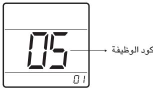
Ceiling Height Selection
This function is to adjust FAN Airflow rate according to ceiling height (For ceiling type product)
1 Press button and button Simultaneously for more than 3 seconds.
2 Setup function code '05' pressing by ROOM TEMP button.
3 Set Thermistor value by pressing button by pressing temperature button.
(01: Remote Controller, 02: Indoor, 03: 2TH)
4 Press 0 button to save.
5 Press button and button Simultaneously for more than 3 seconds After the setting has been completed.
!NOTE
- Ceiling height setting is available only for some products.
- Ceiling height of "Very high" function may not exist depending on the indoor units.
Refer to the product manual for more details.
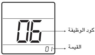
Static Pressure Setting
This function is applied to only duct type. Setting this in cases will cause malfunction.
1 Press button and button Simultaneously for more than 3 seconds.
2 Setup function code '06' pressing by ROOM TEMP button.
3 Set Thermistor value by pressing button by pressing temperature button.
(01: V-H, 02: F-H, 03: V-L, 04: F-L)
| Pressure selection | Function | ||
| Zone state | ESP standard value | ||
| 01 | V-H | Variable | High |
| 02 | F-H | Fixed | High |
| 03 | V-L | Variable | Low |
| 04 | F-L | Fixed | Low |
4 Press 0 button to save.
5 Press button and button Simultaneously for more than 3 seconds After the setting has been completed.
Remote Controller Master/Slave Setting
It's a function for setting in group control, or 2-remote controller control.
1 Press button and button Simultaneously for more than 3 seconds.
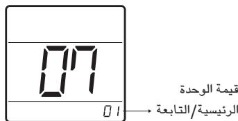
2 Setup function code '07' pressing by ROOM TEMP button.
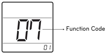
3 Select Master/Slave by pressing temperature button. (00: Slave, 01: Master)
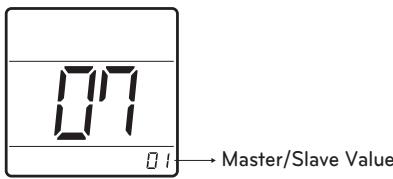
4 Press 0 button to save.
5 Press button and button Simultaneously for more than 3 seconds After the setting has been completed.
| Remote Controller | Function |
| Master | Indoor unit operates based on master remote controller at group control. (master is set when delivering from the ware-house.) |
| Slave | Setup all remote controllers except one master remote contrrooler to slave at group control. |
-
Refer to eh 'Group control' part for details.
-
When controlling in groups, basic operation settings, airflow strength, weak/medium,strong, lock setting of the remote controller, time settings, and other functions may be restricted.
This function is used for switching the display between Celsius and Fahrenheit. (Optimized only for U.S.A)
1 Press button and button Simultaneously for more than 3 seconds.
2 Setup function code '12' pressing by ROOM TEMP button.
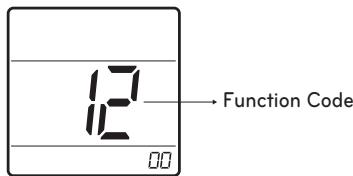
3 Select Temperature unit mode by temperature button. (00: Celsius, 02: Fahrenheit)
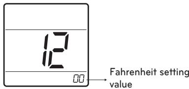
4 Press button to save.
5 Press button and button Simultaneously for more than 3 seconds After the setting has been completed.
Whenever press button in Fahrenheit mode, the temperature will increase/drop 2 degrees.
OWNER'S INSTRUCTION
Standard Operation
- The operation mode can be set from Central Controller only.
Cooling Mode
It cools the room by comfortable and Clean wind.
1 Press the 0 button.
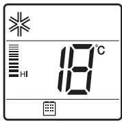
2 Adjust the desired temperature by press the temperature button.
(Temp range: 18^ 30^ ( 64^ 86^ )
Heating Mode
It supplies warm wind to the indoor.
1 Press the 0 button.
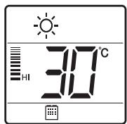
2 Adjust the desired temperature by press the temperature button.
(Temp range: 16^ 30^ ( 60^ 86^ )
Auto Operation Mode
It makes the room cool using pleasant and fresh air quickly
1 Press the 0 button.
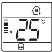
2 When the room temperature is lower than the desired temperature
Heating Operation starts (For Heat Pump models only)
When the room temperature is higher than the desired temperature
: Cooling Operation starts
Dehumidification Mode
It removes humidity while ari-cooling Weakly.
1 Press the ① button.
Fan Mode
It blows the air as it is in the indoor, not
1 Press the 0 button.
- Temperature control is not available during the Dehumidification & Fan operation.
Function setting
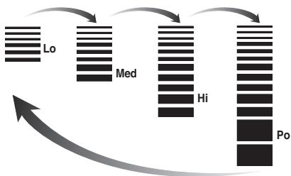
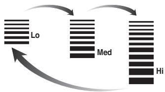
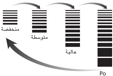
Fan Speed Selection
You can easily control the fan speed.
1 Press the 0 button.
2 Press the FAN button.
Fan Speed Selection in Cooling Operation
Fan Speed Selection in Heating, Dry, Fan, Auto-Operation
NOTE
- If the product is not compatible with The fan speed control, it will not function as per your selection.
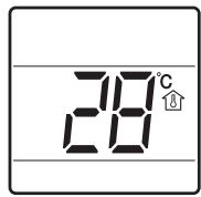
Room Temperature Check
1 Press the button.
NOTE
- "To change the temperature display to Celsius or Fahrenheit, change LCD display by referring to page 14."
- As the temperature distribution of the remote controller installation space is not Uniform, slight difference can be generated between the actually felt temperature and the room temperature indication of the remote controller.
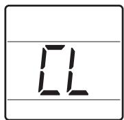
Child Lock
It is the function to use preventing children or others from careless using.
1 Press button and FAN button Simultaneously for more than 3 seconds.
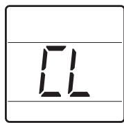
NOTE
- After the setting of the 'CL', if another button is setup, the button can not be recognized as the 'CL' is indicated at the temperature display section.
MANUALE DELL'UTILIZZATORE
EDI INSTALLAZIONE
CABLAGGIO REMOTO
SEMPLICE CONTROLLORE
Setting Address of Central control
- If the product is not compatible with The fan speed control, it will not function as per your selection.
MANUEL D'INSTALLATION
ET D'UTILISATION
DISPOSITION DE RÉGULATION À DISTANCE FILAIRE SIMPLIFIÉ
This is the functional that decides the strength of the wind for each wind level and because this function is to make the installation easier.
(01: V-H, 02: F-H, 03: V-N, 04: F-L)
- When controlling in groups, basic operation settings, airflow strength, weak/medium,strong, lock setting of the remote controller, time settings, and other functions may be restricted.
aaijaiydi y jiaiall jaiy iiaiy


o o aal yaiyaiyaiyaiyaiyaiyaiyaiyaiyaiyaiyaiyaiyaiyaiyaiyaiyaiyaiyaiyaiyaiyaiyaiyaiyaiyaiyaiyaiyaiyaiyaiyaiyaiyaiyaiyaiyaiyaiyaiyaiyaiyaiyaiyaiyaiyaiyaiyaiyaiyai
slll lilll l l l l l l l l l l l l l l l l l l l l l l l l l l l l l l l l l l l l l l l l l l l l l l l l l l l l l l l l l l l l
j 1 j 1 1 1 1 1 1 1 1 1 1 1 1 1 1 1 1 1 1 1 1 1 1 1 1 1 1 1 1 1
aalalalalalalalalalalalalalalal
VANEBBB

TEMP

一

ROOMTEMP

LG
-
alll 1sijl jolpall
ciilll lalai jlln aee
gssallpsilligisb
gSall kail Iusil piai wll aibbll
1 1
FLOOM 1 jll le baiyll " 4" Jueyiyie gds
aall aagaae gaaal
- ( 0) jjglb
J 1 J 1 J 1 J 1 J 1 J 1 J 1 J 1 J 1 J 1 J 1 J 1 J 1 J 1 J 1 J 1 J 1 J 1 J 1 J 1 J 1 J 1 J 1 J 1
1
S ACD = S COD + S_ BDO
jll jll lbe baiall baii 1. yjbjll Jyjll Jyjll Jyjll Jyjll Jyjll Jyjll Jyjll
golal
J 10000000000000000000000000000000000000000000000
1
T
.2j 100000000000000000000000000000000000000000000000000000000000000
10
0
ab = 12
Lai Jiaiaill gaielisauiu LgTHy
jll jll jll jll jll jll jll jll jll jll jll jll jll jll jll jll jll jll jll jll jll jll jll jll jll jll jll jll jll jll jll jll jll jll jll jll jll jll jll jll jll jll jll jll
j j 1 1 1 1 1 1 1 1 1 1 1 1 1 1 1 1 1 1 1 1 1 1 1 1 1 1 1 1 1 1 1 1
E.S.P
gssu klaa aaiy jglll aaij y gdd gill aagll gll
jbs j j k sb 2a bgs ESP aasb 1i -
jally aolzaiyao alulalqullilyalio
giiiy baiy
a a a a a a a a a a a a a a a a a a a a a a a a a a a
1 1
Rc0RM 1 jll lc bll "y" Jlal y aagd gS
.1J 1000000000000000000000000000000000000000000000000000
aag aJzg Jzg Jzg bgs yaaiaa aiaa aiaa Jzg jll no gaiial aayll) aill gaijll aayll (aill gaiy
1 1
1
.1jll 2 j j j b iil y jll 11 all 11 (TH
- ( 1) ① j 5k 偶数
joojj j j j j j j j j j j j j
ab = 12
#
ROOM 251 JLL CBALL "Y" 100000000000000000
jle bai: aaii jll sall/aaiaai lal jil (aaiy jll sall: · · · ,aiiLiill sall: · · · .sJrJl
ab ① j l c + d = 1
joojj 1 j j j j j j j j j j j j
| الإستعمال | الإستعمال |
| الإستعمال مصCarthy جامعية بعبيا بعبيا بعبيا بعبيا بعبيا بعبيا بعبيا بعبيا بعبيا بعبيا بعبيا بعبيا بعبيا بعبيا بعبيا بعبيا بعبيا بعبيا بعبيا بعبيا بعبيا بعبيا بعبيا بعبيا بعبيا بعبيaga بعبيaga بعبيaga بعبيaga بعبيaga بعبيaga بعبيaga بعبيaga بعبيaga بعبيaga بعبيaga بعبيaga بعبيaga بعبيaga بعبيaga بعبيaga بعبيaga بعبيaga بعبيaga بعبيaga bga بعبيaga بعبيaga bga بعبيaga bga bga bga bga bga bga bga bga bga bga bga bga bga bga bga bga bga bga bga bga bga bga bga bga bga bga bga bga bga bga bga bga bga bga bga bga bga bga bga bga bga bga bga bga bga bga bga bga bga bga bGA bga bga bga bga bga bga bga bga bga bga bga bga bga bga bga bga bga bga bga bga bga bga bga bga bga bga bga bga bga bga bga bga bga bga bga bga bga bga bga bga bga bga bga bga bga bga bga bga bga bGa bga bga bga bga bga bga bga bga bga bga bga bga bga bga bga bga bga bga bga bga bga bga bga bga bga bga bga bga bga bga bga bga bga bga bga bga bga bga bga bga bga bga bga bga bga bga bga bga bga bqa bga bga bga bga bga bga bga bga bga bga bga bga bga bga bga bga bga bga bga bga bga bga bga bga bga bga bga bga bga bga bga bga bga bga bga bga bga bga bga bga bga bga bga bga bga bga bga bga bga bgd gga بعس بعس بعس بعس بعس بعس بعس بعس بعس بعس بعس بعس بعس بعس بعس بعس بعس بعس بعس بعس بعس بعس بعس بعس بعس بعس بعس بعس بعس بعس بعس بعس بعس بعس bga bga bga bga bga bga bga bga bga bga bga bga bga bga bga bga bga bga bga bga bga bga bga bga bga bga bga bga bga bga bga bga bga bga bga bga bga bga bga bga bga bga bga bga bga bga bga bga bga bxa bga bga bga bga bga bga bga bga bga bga bga bga bga bga bga bga bga bga bga bga bga bga bga bga bga bga bga bga bga bga bga bga bga bga bga bga bga bga bga bga bga bga bga bga bga bga bga bga bga bgarbga bga bga bga bga bga bga bga bga bga bga bga bga bga bga bga bga bga bga bga bga bga bga bga bga bga bga bga bga bga bga bga bga bga bga bga bga bga bga bga bga bga bga bga bga bga bga bga bga bga ba | الإستعمال |
aJzalgclallll 10000000000000000000
jlll lcll jbi jdi,lcgagall g kllll jie 11.1 (gaa/bwgs/aas) alglf g a g aas L J 10.1 g clll 44 Jaa .
① 2j S ② 3j S
aiaiaiaiaiaiaiaiaiaiaiaiaiaiaiaiaiaiaiaiaiaiaiaiaiaiaiaiaiaiaiaiaiaiaiaiaiaiaiaiaiaiaiaiaiaiaiaiaiaiaiaiaiaiaiaiaiaiaiaiaiaiaiaiaiaiaiaiaiaiaiaiaiaiaiaiaiaiaiaiaiaiaiaiaiaiaiaia
aJrJrJrJrJrJrJrJrJrJrJrJrJrJrJrJrJrJrJrJrJrJrJrJrJrJrJrJrJrJrJrJrJrJrJrJrJrJrJrJrJrJrJrJrJr
aagblllglg
Lg gglgglgglgglgglg
① 2j S ②
aagall
1 1
2x - 6 = 2x - 3 + 2k , ,k z
a 1 1 1 1 1 1 1 1 1 1 1 1 1 1 1 1 1 1 1 1 1 1 1 1 1
山
Jll
1
y
aaii i 1
①②③
a jy jie biaaiy ball a yjbdai (a yj 1
a yj r 一 1 :a jllb) .yjall (a yjoo
a
-
-
-
-
-
-
-
-
-
-
-
-
- 1.
-
-
-
-
-
-
-
-
-
-
-
①②③
a jy jie baii yibai ball a jyblal a jyblal a jyj 17:ajlal a jyj (24
gaii jiai i
sglll pluull yurjzr jll Jg l 11 gll lla s
a
ROOM TEMP
ab 为 y = ax^2 + bx + c

a a a a a a a a a a a a a a a a a a
LCD 1
1.12
jck jks k a jz jz jz jz
Jalll aagwaaall yjll jy
Jably
juc puiu 11 jno pauee gul bgl qal aagll oia puiu
1 1
ab 为 y = a + bx_0

jll jy jj jucllCL,abg b
jcl jll jj
.
Jg
aay
a
①②③
FAN 7
jll jssg g aagall aas
aag aegg aegaae
glll lssssssss

ab 与 b < 3

aagall aegssg kail gaiy jlll
djiis jis