PHO 20-82 - Planer BOSCH - Free user manual and instructions
Find the device manual for free PHO 20-82 BOSCH in PDF.
User questions about PHO 20-82 BOSCH
0 question about this device. Answer the ones you know or ask your own.
Ask a new question about this device
Download the instructions for your Planer in PDF format for free! Find your manual PHO 20-82 - BOSCH and take your electronic device back in hand. On this page are published all the documents necessary for the use of your device. PHO 20-82 by BOSCH.
USER MANUAL PHO 20-82 BOSCH
PHO 16-82 PHO 20-82
Deutsch
English
Français
Espanol
Portugués
Italiano
Nederland
Dansk
Svenska
Norsk
Suomi
Eλληνικά
Türkce

Gerätekennwerte
Senior Vice President
Engineering
Dr. Eckerhard Strötgen
Head of Product
Certification


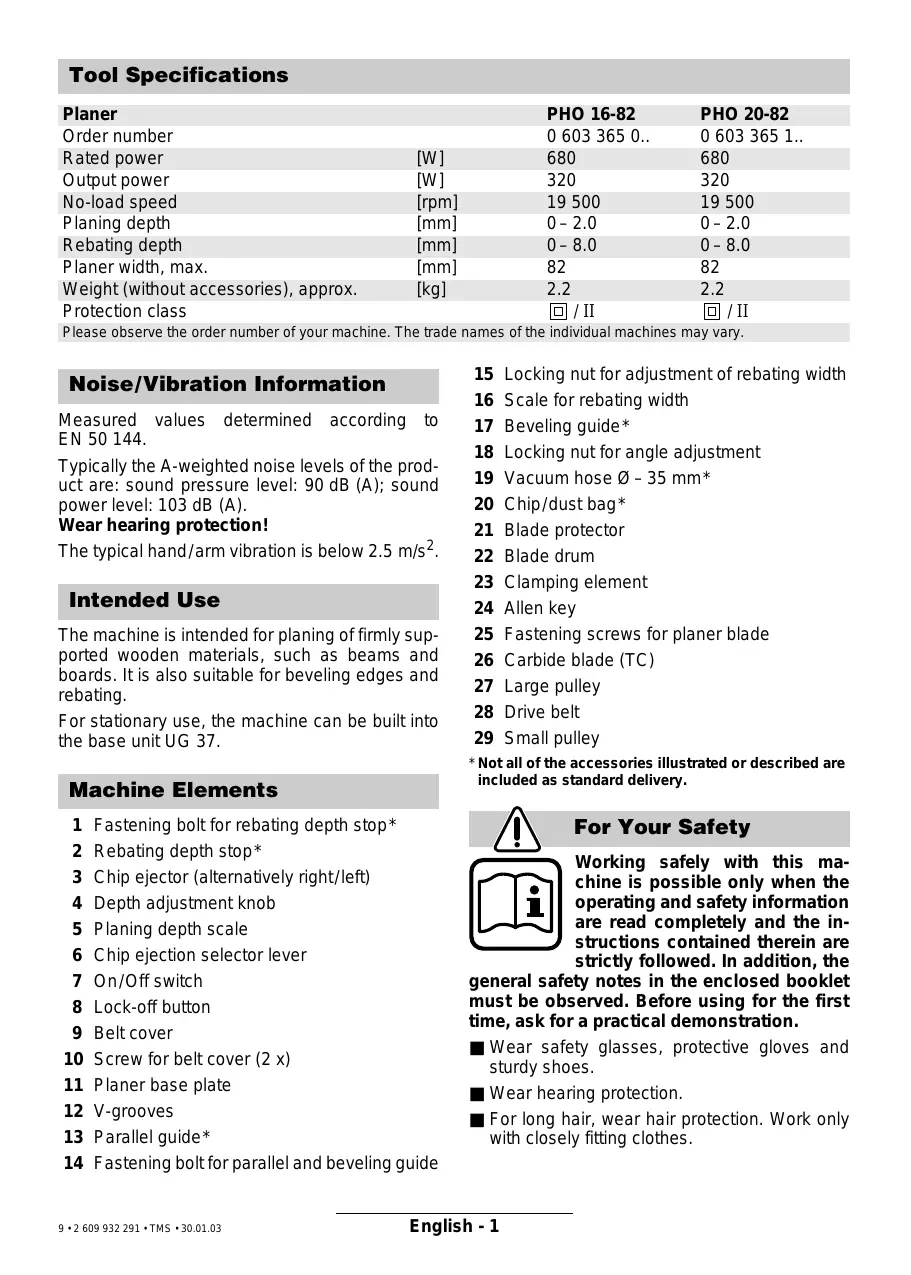
| Planer | PHO 16-82 | PHO 20-82 | |
| Order number | 0 603 365 0.. | 0 603 365 1.. | |
| Rated power | [W] | 680 | 680 |
| Output power | [W] | 320 | 320 |
| No-load speed | [rpm] | 19 500 | 19 500 |
| Planing depth | [mm] | 0-2.0 | 0-2.0 |
| Rebating depth | [mm] | 0-8.0 | 0-8.0 |
| Planer width, max. | [mm] | 82 | 82 |
| Weight (without accessories), approx. | [kg] | 2.2 | 2.2 |
| Protection class | ☐ / II | ☐ / II |
Please observe the order number of your machine. The trade names of the individual machines may vary.
Noise/Vibration Information
Measured values determined according to EN 50 144.
Typically the A-weighted noise levels of the product are: sound pressure level: 90 dB (A); sound power level: 103 dB (A).
Wear hearing protection!
The typical hand/arm vibration is below 2.5m / s^2
Intended Use
The machine is intended for planing of firmly supported wooden materials, such as beams and boards. It is also suitable for beveling edges and rebating.
For stationary use, the machine can be built into the base unit UG 37.
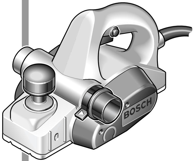
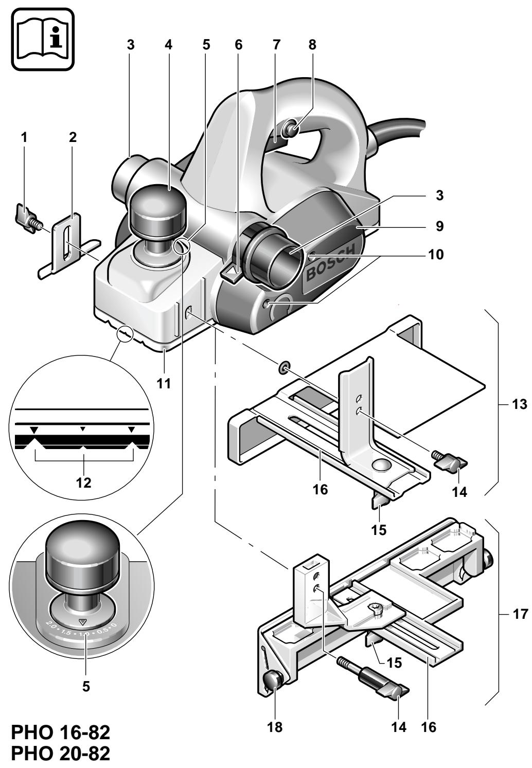
Machine Elements
1 Fastening bolt for rebating depth stop
2 Rebating depth stop
3 Chip ejector (alternatively right/left)
4 Depth adjustment knob
5 Planing depth scale
6 Chip ejection selector lever
7 On/Off switch
8 Lock-off button
9 Belt cover
10 Screw for belt cover (2 x)
11 Planer base plate
12 V-grooves
13 Parallel guide*
14 Fastening bolt for parallel and beveling guide
15 Locking nut for adjustment of rebating width
16 Scale for rebating width
17 Beveling guide
18 Locking nut for angle adjustment
19 Vacuum hose -35mm^
20 Chip/dust bag*
21 Blade protector
22 Blade drum
23 Clamping element
24 Allen key
25 Fastening screws for planer blade
26 Carbide blade (TC)
27 Large pulley
28 Drive belt
29 Small pulley
- Not all of the accessories illustrated or described are included as standard delivery.
For Your Safety
Working safely with this machine is possible only when the operating and safety information are read completely and the instructions contained therein are strictly followed. In addition, the
general safety notes in the enclosed booklet must be observed. Before using for the first time, ask for a practical demonstration.
Wear safety glasses, protective gloves and sturdy shoes.
Wear hearing protection.
For long hair, wear hair protection. Work only with closely fitting clothes.
If the mains cable is damaged or cut through while working, do not touch the cable but immediately pull the mains plug. Never use the machine with a damaged cable.
Connect machines that are used in the open via a residual current device (RCD) with an actuating current of 30mA maximum. Use only extension cables that are approved for outdoor use.
Always direct the cable to the rear away from the machine.
Apply the machine to the workpiece only when switched on.
Use only sharp planing blades.
Always hold the machine firmly when working and ensure a secure stance.
- Keep hands away from rotating parts.
- Secure the workpiece. A workpiece clamped with clamping devices or in a vice is held more secure than by hand.
The planer base plate 11 must lay flat on the surface when working.
- Never plane over metal objects such as nails or screws.
Do not allow fingers to enter the chip ejector 3.
Always switch the machine off and wait until it has come to a standstill before placing it down.
For stationary use as a panel planer together with base unit UG 37 and the respective accessories:
- Pull the mains plug before mounting.
- Use the blade-shaft protector at all times.
- Work small workpieces only with a suitable feeding device, e. g. a piece of wood.
- Use the switching device belonging to the accessory.
Never allow children to use the machine.
Bosch is only able to ensure perfect operation of the machine if the original accessories intended for it are used.
Initial Operation
Observe correct mains voltage: The voltage of the power source must agree with the voltage specified on the nameplate of the machine. Equipment marked with 230V can also be connected to 220V .
Switching On and Off
To start the machine, press the lock-off button 8 against starting first, then press and hold the On/Off switch 7.
To switch off the machine, release the On/Off switch 7.
For safety reasons the On/Off switch of the machine cannot be locked; it must remain pressed during the entire operation.
Adjusting the Planing Depth
The planing depth can be adjusted variably from 0 - 2.0mm with the adjustment knob 4, using the planing depth scale 5:
Rotation in counterclockwise direction reduces the planing depth
Rotation in clockwise direction = increases the planing depth
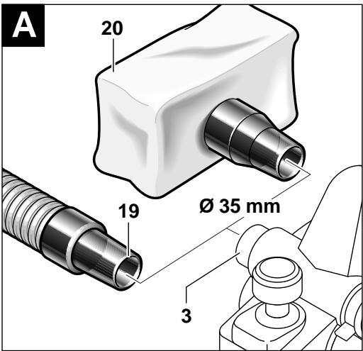
Dust/Chip Extraction (see figure A)
Before any work on the machine itself, pull the mains plug.
The dust that is produced while working can be detrimental to health, inflammable or explosive. Suitable safety measures are required.
Examples: Some dusts are regarded as carcinogenic. Use suitable dust/chip extraction and wear a dust respirator.
Clean the chip ejector 3 regularly. Use a suitable tool (e.g. piece of wood, compressed air, etc.) to clean clogged chip ejector. Do not allow fingers to enter the chip ejector 3.
To ensure optimum extraction of chip/dust chips, attach the vacuum hose 19 or the chip/dust bag 20 tightly onto the chip ejector 3.
External Dust Extraction
The chip ejector 3 fits on both sides for direct connection of the Bosch vacuum hose -35mm19 (accessory). When using other vacuum hose systems a suitable extraction adapter may be required.
The vacuum cleaner must be suitable for the material to be worked.
When vacuuming dry dust that is especially detrimental to health or carcinogenic, use a special vacuum cleaner.
Integrated Dust Extraction
A chip/dust bag 20 (accessory) can be used for smaller jobs.
Empty the chip/dust bag regularly. Remove the chip/dust bag, open the zipper and empty the chip/dust bag.
Choice of Chip Ejector Side (Right/Left)
The chip ejector 3 can be switched to the right or left with the selector lever 6.
Always press the change lever until it engages in the end position.
The selected ejector direction is marked with an arrow.
Operating Instructions
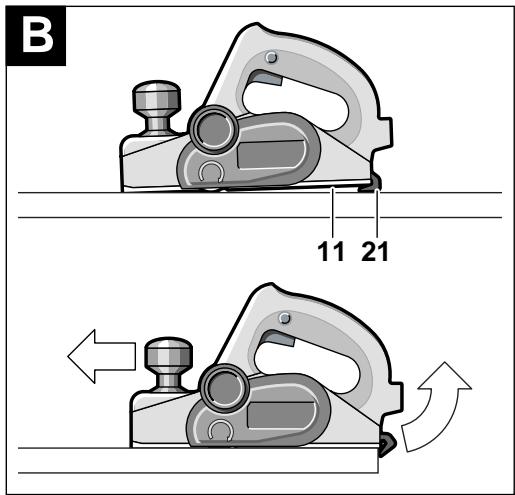
Blade Protector (see figure B)
The blade protector 21 allows the machine to be set down directly after operation, without danger of damaging the working surface or the planer blade.
When planing, the blade protector 21 is tilted upwards thus enabling full contact of the rear part of the planer base plate 11.
For stationary use (e.g. with base unit UG 37), the blade protector must be removed. Press the blade protector together from the sides and pull it off.
For non-stationary use, the blade protector must always be assembled.
Planing
Set the required planing depth and place the front part of the planer base plate 11 against the workpiece.

Caution! Danger of kickback!
Apply the machine to the workpiece only when switched on.
Switch the machine on and guide the machine with an even feed over the surface to be planed.
To achieve high-grade surfaces, work only with low feed and apply pressure on the centre of the planer base plate.
When machining hard materials (e.g. hardwood) as well as when utilising the maximum planer width, set only low planing depths and reduce planer feed, as required. Repeat the planing several times.
Excessive feed reduces the surface quality and can lead to rapid clogging of the chip ejector.
Only sharp blades achieve good cutting capacity and give the machine longer life.
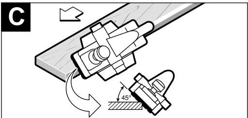
Beveling Edges (see figure C)
The V-grooves 12 in the front planer base plate 11 allow quick and easy beveling of workpiece edges. Depending on required bevel width, use the corresponding V-groove.
For this, place the planer with the V-groove 12 onto the edge of the workpiece and guide along the edge.
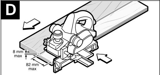
Using the Parallel/Beveling Guide (Accessory - see figure D)
Mount parallel guide 13 or beveling guide 17 to the machine using fastening bolt 14 and rebating depth stop 2 using fastening bolt 1.
Loosen locking nut 15 and adjust the required rebating width with the scale 16. Retighten locking nut 15 again.
Adjust the required rebating depth accordingly with the rebating depth stop 2.
Carry out the planing procedure several times, until the required rebating depth is reached. Pay attention that the planer is guided with sideward supporting pressure.
Beveling (only beveling guide 17)
When beveling rebates and surfaces, adjust the required slope angle with the angle adjustment 18.
Replacing the Planer Blade
Before any work on the machine itself, pull the mains plug.
■ Be cautious when replacing the planer blades: Possible danger of injury due to the sharp cutting edges of the planer blades! Do not grasp the planer blades by the cutting edges.
Use only original Bosch carbide blades (TC).
The carbide blade (TC) has 2 cutting edges and can be reversed.
When both cutting edges are dull, the planer blade must be replaced. The carbide blade (TC) may not be resharpened.
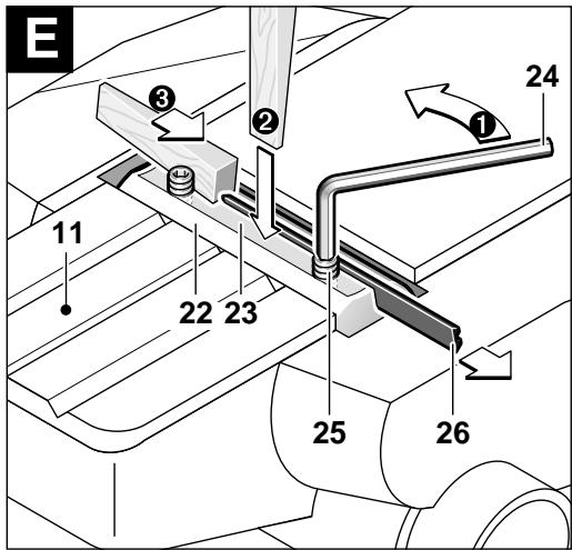
Disassembling the Planer Blades (see figure E)
To reverse or replace the planer blade, rotate the blade drum 22 until it is parallel to the planer base plate 11.
1 Loosen the two fastening screws 25 with the Allen key 24 by approx. 1-2 turns.
If necessary, loosen the clamping element 23 by giving it a light blow with a suitable tool (e. g. a wooden wedge).
Push the planer blade 26 sideways out of the blade drum with a piece of wood.
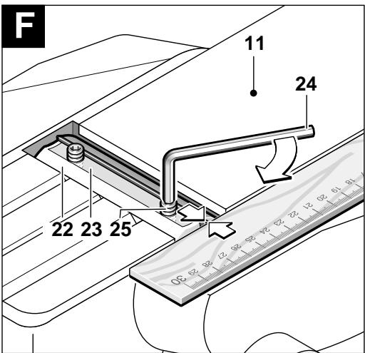
Assembling the Planer Blades (see figure F)
The guide groove of the planer blade always ensures continuous height adjustment when replacing or reversing it.
Clean the blade seat (clamping element) and the planer blade respectively, if required.
When assembling the planer blade, ensure that it is seated properly in the blade holder of the clamping element 23 and aligned flush at the side edge of the rear planer base plate 11.
Afterwards tighten the fastening screws 25 again.
Before restarting, check if the clamping screws 25 are tightened well.
Rotate the blade drum 22 by hand and ensure that the planer blade does not run into the planer base plate or housing.
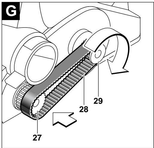
Replacing the Drive Belt (see figure 6)
Before any work on the machine itself, pull the mains plug.
Loosen screw 10 and take off the belt cover 9. Remove worn drive belt 28.
Before assembling a new drive belt, clean both belt pulleys 27 and 29.
Place the new drive belt on the small pulley 29 first and then work it on the large pulley 27 by hand while rotating.
Reattach the belt cover 9 and tighten with the screw 10.
Maintenance and Cleaning
Before any work on the machine itself, pull the mains plug.
For safe and proper working, always keep the machine and the ventilation slots clean.
If the machine should fail despite the care taken in manufacturing and testing procedures, repair should be carried out by an after-sales service centre for Bosch power tools.
In all correspondence and spare parts orders, please always include the 10-digit order number given on the nameplate of the machine.
WARNING! Important instructions for connecting a new 3-pin plug to the 2-wire cable.
The wires in the cable are coloured according to the following code:
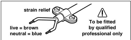
Do not connect the blue or brown wire to the earth terminal of the plug.
Important: If for any reason the moulded plug is removed from the cable of this machine, it must be disposed of safely.
Environmental Protection

Recycle raw materials instead of disposing as waste
The machine, accessories and packaging should be sorted for environmental-friendly recycling.
These instructions are printed on recycled paper manufactured without chlorine.
The plastic components are labelled for categorized recycling.
Service and Customer Assistance
www.bosch-pt.com
Great Britain
Robert Bosch Ltd. (B.S.C.)
P.O.Box 98
Broadwater Park
North Orbital Road
Denham-Uxbridge
MIDDLEX UB 95HJ
Service. +44 (0) 18 95 / 83 87 82
Advice line +44 (0) 18 95 / 83 87 91
Fax. +44 (0) 18 95 / 83 87 89
Ireland
Beaver Distribution Ltd.
Greenhills Road
Tallaght-Dublin 24
Service +353 (0)1 / 414 9400
Fax. +353 (0)1 / 459 8030
Australia
Robert Bosch Australia Ltd.
RBAU/SPT2
1555 Centre Road
P.O. Box 66 Clayton
3168 Clayton/Victoria
+61 (0)1 / 800 804 777
Fax. +61 (0)1 / 800 819 520
www.bosch.com.au
E-Mail: CustomerSupportSPT@au.bosch.com
New Zealand
Robert Bosch Limited
14-16 Constellation Drive
Mairangi Bay
Auckland
New Zealand
C∈ Declaration of Conformity
We declare under our sole responsibility that this product is in conformity with the following standards or standardization documents: EN 50 144 according to the provisions of the directives 89/336/EEC, 98/37/EC.
Dr. Egbert Schneider
Senior Vice President
Engineering
Dr. Eckerhard Strötgen
Head of Product
Certification
ppa. /mu: i.v. nuoycu
Subject to change without notice
\section*{Caracteristiques techniques}
Attention! Risque de contreoup!
Robert Bosch France S.A.
ServiceAprès-vente/Outillage
Service consail client,
After Sales Service Outillage
Rue Henri Genesse 1
1070 Bruxelles
+32 (0)2/525.50.29
Fax. +32 (0)2/525.54.30
Service conseil client.....+32 (0)2 / 525.53.07
E-Mail: Outillage.Gereedschappen@be.bosch.com
Suisse
+41(0)1/8471616
Fax. +41 (0)1/8 47 16 57
Senior Vice President
Engineering
Dr. Eckerhard Strötgen
Head of Product
Certification

i.v. Mo Tu We Th Fr So Su
Senior Vice President
Engineering
Dr. Eckerhard Strötgen
Head of Product
Certification
paa / 100 i.v. nuoy
Senior Vice President
Engineering
Dr. Eckerhard Strötgen
Head of Product
Certification
paa / 134 i.v. nuoju
Senior Vice President
Engineering
Dr. Eckerhard Strötgen
Head of Product
Certification

i.v. Mo Tu We Th Fr So Su
Dr. Egbert Schneider Senior Vice President Engineering
Dr. Eckerhard Strötgen
Head of Product Certification


Senior Vice President
Head of Product
Engineering
Certification


Dr. Egbert Schneider Dr. Eckerhard Strötgen Senior Vice President Head of Product Engineering Certification
paa / 1000 i.v. nuoy
Senior Vice President
Engineering
Dr. Eckerhard Strötgen
Head of Product
Certification


Senior Vice President
Engineering
Dr. Eckerhard Strötgen
Head of Product
Certification


II npopopoiεγiaθopuβo kai dovnoeic
EeakpiBOWTowTVIuovMuTePnOscoupWVA EN50144.
H ouqwva e Tnv kaunuA ektiuntheta a
otaun opuou tou nxaavmuato
avextal e: Taun akouotikns iieonc
90 dB (A). Taun nxntiknloxuoc
103 dB (A).
Φopατε ωτασηδες!
O xaapaktnpiotikoc Kpaadaaooc xepiou- mnpataoo eivai xaunloTepcoc ano 2,5 m/s².
Senior Vice President
Engineering
Dr. Eckerhard Strötgen
Head of Product
Certification
paa / 1000 i.v. nuoy
Bosch San. ve Tic. A.S.
Ahi Evran Cad. No:1 Kat:22
Polaris Plaza
80670 Maslak/Istanbul
+90 (0)212 / 335 06 00
Faks +90 (0)212 / 346 00 48-49
C∈Uygunluk beyani
Senior Vice President
Engineering
Dr. Eckerhard Strötgen
Head of Product
Certification


Printed in Switzerland - Imprimé en Suisse