
HORIZON ELECTROL - Electric projection screen DA-LITE - Free user manual and instructions
Find the device manual for free HORIZON ELECTROL DA-LITE in PDF.
| Product type | Electric projection screen |
| Brand | DA-LITE |
| Model | HORIZON ELECTROL |
| Preset image formats | NTSC (1.33:1), HDTV (1.78:1), Letterbox (1.85:1), Anamorphic (2.35:1) |
| Number of motors | 2 (screen and mask) |
| Control type | 6-button wall switch |
| Power supply | 240 V |
| Thermal protection | Yes, automatic shut-off in case of overheating |
| Installation methods | Flush ceiling mount (methods A, B, C) |
| Wiring | T6 and T4 cables with adapter |
| Transformer | Yes, plugged into the non-motor side outlet |
| Button functions | Up, stop, 4 preset formats |
| Limit adjustment | Possible via switch and dipswitch |
| Safety | Do not disassemble, risk of electric shock |
| Maintenance | Do not cut the ribbon with a sharp object |
| Repairability | Sealed motor, contact an authorized service center |
Frequently Asked Questions - HORIZON ELECTROL DA-LITE
User questions about HORIZON ELECTROL DA-LITE
0 question about this device. Answer the ones you know or ask your own.
Ask a new question about this device
Download the instructions for your Electric projection screen in PDF format for free! Find your manual HORIZON ELECTROL - DA-LITE and take your electronic device back in hand. On this page are published all the documents necessary for the use of your device. HORIZON ELECTROL by DA-LITE.
USER MANUAL HORIZON ELECTROL DA-LITE
PRESENTATION PRODUCTS
Instruction Book for HORIZON ELECTROL®

DA-LITE SCREEN COMPANY, INC.
3100 North Detroit Street
Post Office Box 137
Warsaw, Indiana 46581-0137
Phone: 574-267-8101
800-622-3737
Fax: 574-267-7804
Toll Free Fax: 877-325-4832
www.da-lite.com
e-mail: info@da-lite.com
IMPORTANT SAFETY INSTRUCTIONS
When using your video equipment, basic safety precautions should always be followed, including the following:
- Read and understand all instructions before using.
- Position the cord so that it will not be tripped over, pulled, or contact hot surfaces.
- If an extension cord is necessary, a cord with a current rating at least equal to that of the appliance should be used. Cords rated for less amperage than the appliance may overheat.
- To reduce the risk of electric shock, do not disassemble this appliance. Contact an authorized service dealer when repair work is required. Incorrect reassembly can cause electric shock when the appliance is used subsequently.
- The use of an accessory attachment not recommended by the manufacturer may cause a risk of fire, electric shock, or injury to persons.
SAVE THESE INSTRUCTIONS
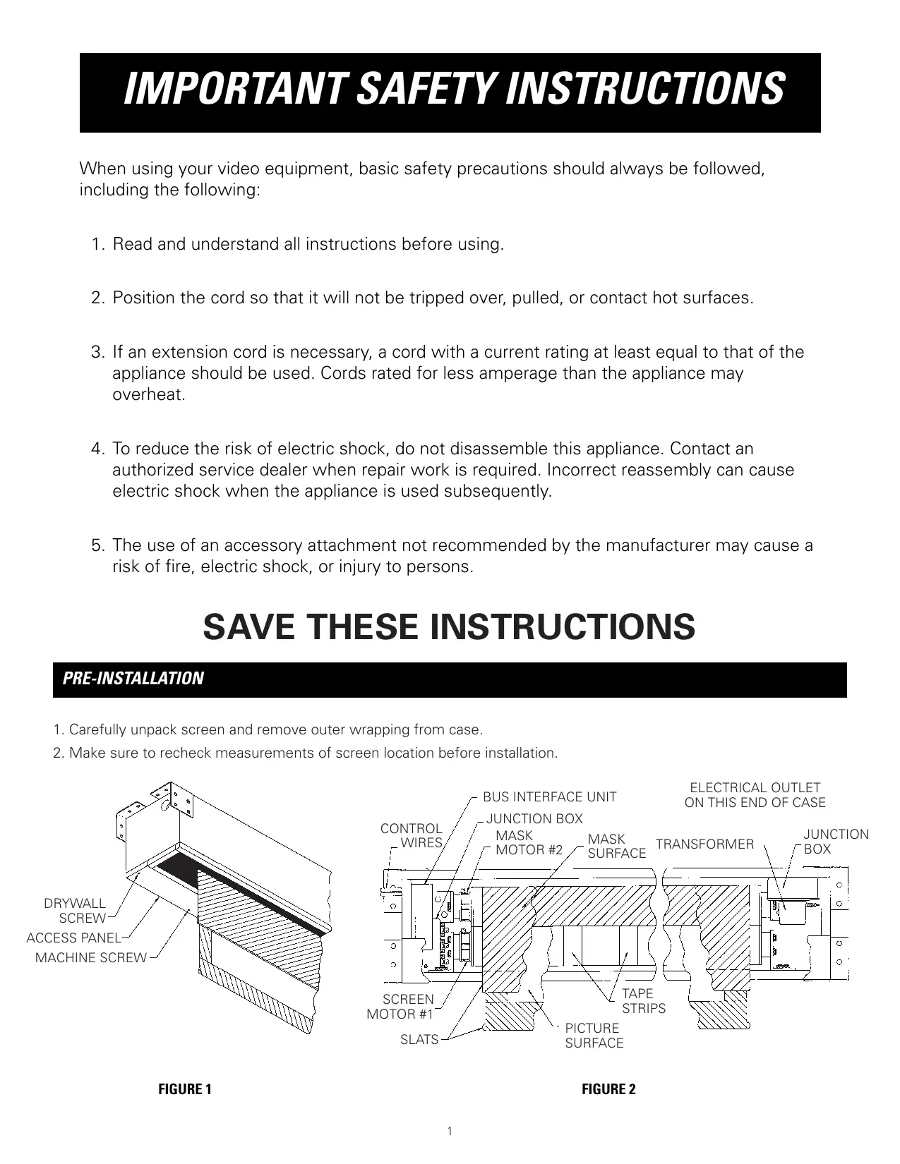
PRE-INSTALLATION
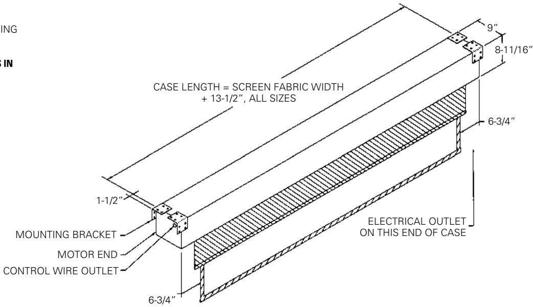
- Carefully unpack screen and remove outer wrapping from case.
- Make sure to recheck measurements of screen location before installation.
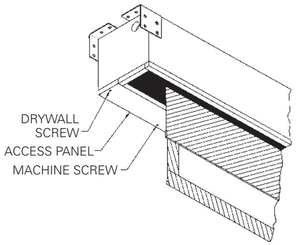
FIGURE 1
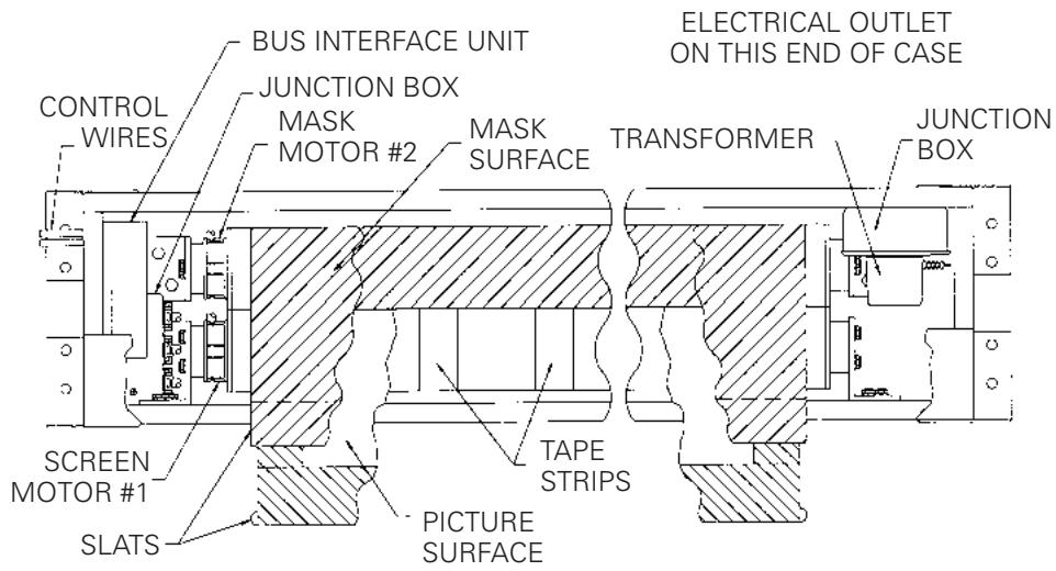
FIGURE 2
INSTALLATION
- Install screen by raising unit into position between joists at one end only. Install one lag screw in each mounting bracket.
- Level unit lengthwise with a carpenter's level and plumb level. Secure opposite end.

Jtion! Do not seal in until screen has been secured in position and properly tested for satisfactory operation.
- Detach access panel by removing screws (Fig. 1).
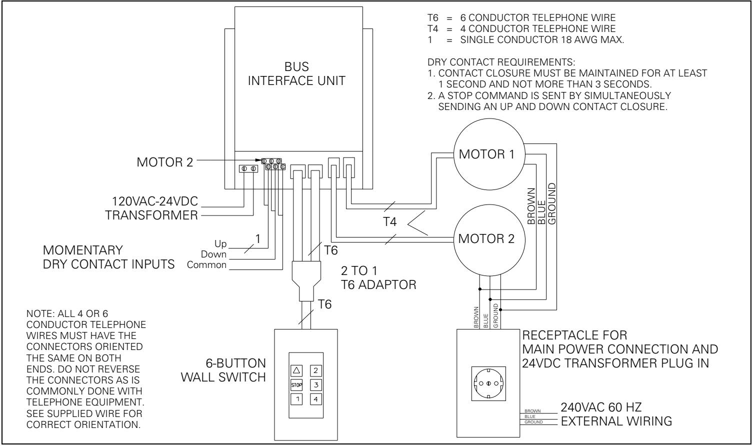
- Unwrap the two T6 cables that are attached to the bus interface control. Route them through the hole in the end of the screen case.
- Run both T6 cables to the wall switch box and connect them to the double end of the 2 to 1, T6 phone jack adapter.
- Plug one end of the remaining short T6 cable into the single plug end of the T6 adapter and plug the other end of the T6 cable into the back of the 6 button wall switch. Install the switch in the box and attach the cover plate.
- Unplug the transformer located on the non-motor end of the screen.
- Remove the receptacle cover plate. Install electrical hook up as shown in the wiring diagram.
NOTE: Screen has been internally wired at Da-Lite. Wiring designated "external" is completed by installer conforming to local and national codes.
- After the electrical connections are completed replace the cover plate and reinstall the transformer into the receptable.

CAUTION! DO NOT CUT TAPE ON FABRIC WITH A KNIFE OR ANY SHARP TOOL. REMOVE BY PULLING TAB ATTACHED TO ORANGE STRING.
- Carefully remove two wood boards securing mask surface to case.
- Test installation by carefully running picture and mask surfaces up and down several times. Be prepared to stop screen. IMPORTANT. READ OPERATING INSTRUCTIONS BEFORE TESTING SCREEN.
NOTE: When rolled down, the picture surface should wrap fully around the roller. No part of the roller should be exposed. Picture and mask surfaces will automatically stop in the down position.

CAUTION! Excessive continuous operation may cause overheating. If this happens the motors will shut off until they cool to normal operating temperature.
SCREEN OPERATION
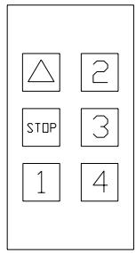
The Horizon screen has been preset to four different formats. The screen can be set to any format by simply pressing the corresponding button on the six-button switch. Below is a list of each button function.
IMPORTANT. When operating the switch, press and release the buttons. DO NOT hold the button for more than three (3) seconds or the button will be reprogrammed to the current screen position.
Returns the screen and mask to the up position.
STOP Stops the screen and mask at any position when pressed.
1 Lovers screen to NTSC (1.33:1) format. Mask will travel down and reverse wrap on the roller. The mask is not used for this format.
2 Sets format to HDTV (1.78:1)
3 Sets format to Letterbox (1.85:1)
4 Sets format to Anamorphic (2.35:1)
SCREEN ADJUSTMENT
The motors on the Horizon Electrol® have been preset to four different screen formats based on your screen size. They are 1.33:1, 1.78:1, 1.85:1 and 2.35:1. It is possible to adjust these formats for your particular needs. If you want to change formats we suggest you contact your Da-Lite Dealer to make the adjustments for you.
The mask surface and the projection screen must be adjusted separately. The following instructions walk you through this process.
SCREEN ADJUSTMENT (MOTOR 1)
- Make sure the power is disconnected to the screen before starting.
- Remove the cover plate from the wall switch, and then remove the switch from the box.
- Unplug the T6 cable marked motor 2 from the T6 adapter.
- Locate the bus interface control. It is located on the motor end of the screen case. Remove the screw that holds the cover shut. Slide the cover back and unplug the T4 wire marked motor 2.
- Reconnect the power to the screen.
- Press the button marked 1 to lower the screen. When the screen reaches the desired level press the stop button. If you go past the desired position, press the stop button to stop the screen and then press the up arrow to return the screen to a position above the new stop point and try again until the screen stops at the new position. The new stop point can now be assigned to whichever format location you want, button 2, 3 or 4. Press and hold in the chosen button for 5 seconds, then release.
- The new stop position is now recorded for the selected button. Repeat this process for any other changes to the remaining 2 locations.
- Make sure the power is disconnected to the screen, then insert the T4 cable marked motor 2 in the jack it was disconnected from on the bus interface control and reconnect the T6 cable to the T6 adapter.
MASK ADJUSTMENT (MOTOR 2)
- Make sure the power is disconnected to the screen before starting.
- Unplug the T4 cable marked motor 1 from the bus interface control.
- Unplug the T6 cable marked motor 1 from the T6 adapter.
- Reconnect the power to the screen.
- Press the button marked 1 to lower the mask. When the mask reaches the desired level press the stop button. If you go past the desired position, press the stop button to stop the mask and then press the up arrow to return the mask to a position above the new stop point and try again until the mask stops at the new position. The new stop point can now be assigned to whichever format location you want, button 2, 3 or 4. Press and hold in the chosen button for 5 seconds, then release.
- The new stop position is now recorded for the selected button. Repeat this process for any other changes to the remaining 2 locations.
- Make sure the power is disconnected to the screen, then insert the T4 cable marked motor 1 in the jack it was disconnected from on the bus interface control, shut the cover and fasten the screw.
- Reconnect the T6 cable marked motor 1 to the 2-1, T6 adapter jack.
- Reinstall the wall switch into the box and attach the cover plate.
- Reconnect the power to the screen.
LIMIT CONTROL ADJUSTMENT
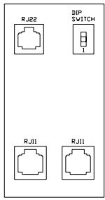
This procedure will reset the stop positions for the "up" button and button 1. If you have a wall switch with just two T6 connectors on the bottom you will need to use a separate 3-button switch for this operation. Otherwise you will use the wall switch that controls the bus interface unit. Below is a diagram of switch you will use.
- Remove cover screw from bus interface unit located on the motor end of screen case.
- Locate the T4 wires coming from the motors to the bus interface (see wiring diagram).
- Unplug the T4 wire of the motor to be adjusted from the bus interface unit and plug it into the top left RJ22 4-pin connector of wall switch.
- Locate the 3-position dipswitch in top right corner of switch. To adjust the down limit flip the switch in the down direction. Press and hold the 1 button on the switch to run the screen down to the desired position. Release the button to stop the screen.
NOTE: If you push the down button and the screen runs in the up direction press and release the stop button. Then press the down button again. This should reverse the motor.
- When the screen is at the desired location flip the dipswitch back in to the middle position.
- To adjust the up limit (the screen should be in down position first) flip the dipswitch to the up direction. Press and hold the up button to run the screen to the desired top position.
- When the screen is at the desired location flip the dipswitch to the middle position. Now press 1 button to make sure the screen stops at the new down position. Then press the up button and watch carefully to make sure it stops in the new up position.
- Unplug the T4 wire from the switch and plug it into the SAME location you unplugged it from the bus interface unit.
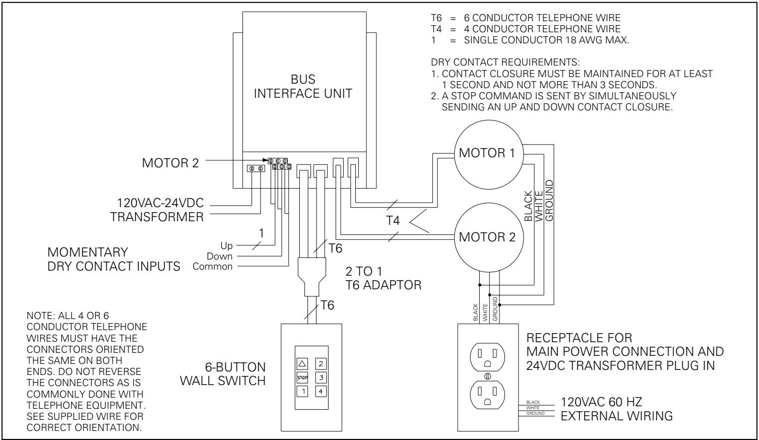
240V WIBING DIAGRAM
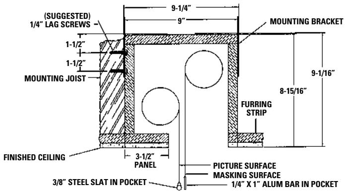
SELECT INSTALLATION METHOD ACCORDING TO CEILING TYPE.
NOTE: MUST MARK HOLE LOCATION OF SCREWS IN 3-1/2" PANEL FOR REMOVAL, IF COVERING WITH TILE.
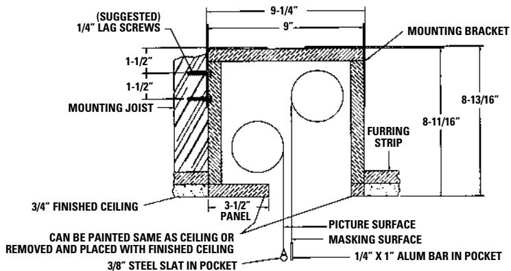
METHOD A
Offset mounting, recessed above ceiling. For plaster, dry wall, tile or paneling. Bottom of case painted same finish as ceiling.
METHOD B
Offset mounting, recessed above ceiling. May be adapted for 3/4 "ceiling, but cut to 1/4 " thick under screen case and panel.
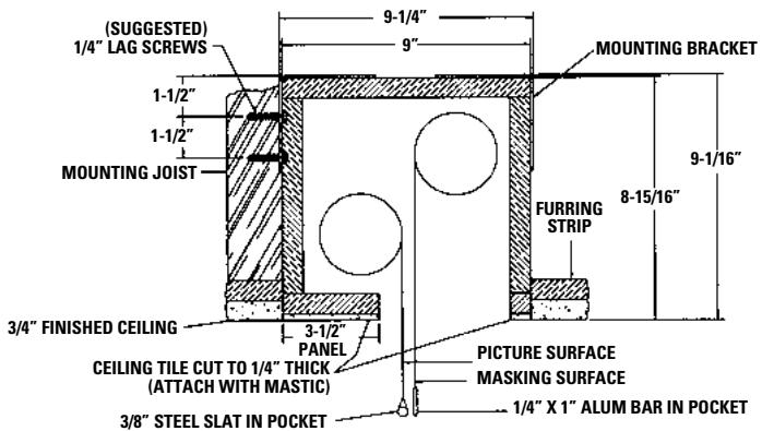
METHOD C
Offset mounting, recessed above ceiling. May be adapted for 1/4 paneling for ceiling.
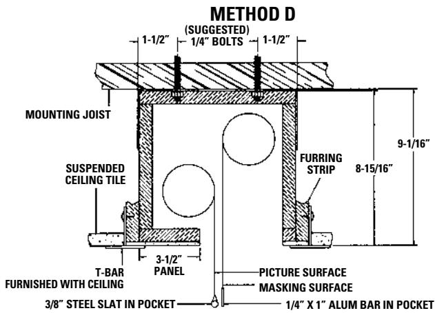
Flush mounting, recessed above ceiling. For use with dropped ceiling. May also be adapted for use with acoustical or other ceiling 3/4 " thick but cut to 1/4 " thick under screen case and panel.
| SYMPTOM | CAUSE | SOLUTION |
| 1. Screen or mask will not operate.Motor does not hum. | (a) Blown facility fuse.(b) Tripped facility circuit breaker.(c) No power to receptacle in junction box.(d) No power to bus interface unit.(e) Loose control wire connectionsPower at junction box(f) Thermal overload tripped.(g) Transformer not plugged in.(h) Defective motor.(i) Temporary binding. | (a) Replace facility fuse.(b) Reset facility circuit breaker.(c) Check above. Tighten all loose wire connections. Recheck wiring. See installation instructions.(d) Make sure transformer is connected to bus interface - see wiring diagram.Defective transformer - replace.(e) Check all T4 and T6 wire connections - see wiring diagram.(f) Let motor cool down for 15 minutes. Try again.(g) Plug transformer into receptacle on non-motor end of screen.(h) Replace motor assembly.NOTE: Motor is a sealed assembly.(i) With power "off," turn roller by hand to free binding. |
| Motor hums. | ||
| 2. Image on screen does not match picture area. | (a) Screen not set to the correct format.(b) Screen or mask out of adjustment. | (a) Set screen to the format being projected.(b) See screen adjustment. We recommend you have your dealer make these adjustments for you. |
| 3. Noise.NOTE: Screen will operate with a low-pitched hum. | (a) Grinding. Foreign object in screen rubbing on roller or fabric. | (a) Remove. |
| 4. Coasting. | (a) Defective brake. | (a) Replace motor assembly. |
| 5. Fabric hangs crooked. | (a) Screen not installed properly.(b) Fabric has backed up inside case.(c) Fabric is damaged. | (a) Check for level and plumb.(b) Lower screen and carefully pull fabric to remove any slack on the roller.(c) Replace fabric. |