
SENIOR ELECTROL - Electric projection screen DA-LITE - Free user manual and instructions
Find the device manual for free SENIOR ELECTROL DA-LITE in PDF.
| Product type | Electric projection screen |
| Brand | DA-LITE |
| Model | SENIOR ELECTROL |
| Power supply | 120 V or 220/240 V AC depending on version |
| Motor power | Standard (not specified, estimated ~100 W) |
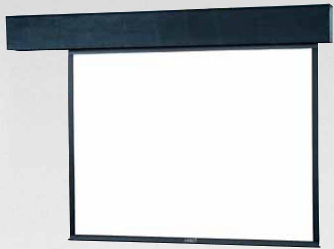
| Housing dimensions | Variable depending on screen size (e.g., up to 18' x 18') |
| Projection surface type | Fabric with built-in tension band on some models |
| Operation | Electric with wall switch or low voltage control (DRC) |
| Automatic stop | By adjustable limit switches |
| Installation | Wall or ceiling mount with brackets provided, recessed |
| Maintenance and cleaning | Wipe the casing with a dry cloth; do not cut the packaging paper with a knife |
| Safety | Grounding mandatory for 240 V models; do not disassemble the motor; allow 15 min cooling in case of overheating |
| Repairability | Motor and limit switches replaceable by a qualified technician |
| Operating temperature | Ambient (avoid excessive heat) |
| Approximate weight | Variable depending on size (e.g., ~15-30 kg) |
| Warranty | Not specified, contact the manufacturer |
Frequently Asked Questions - SENIOR ELECTROL DA-LITE
User questions about SENIOR ELECTROL DA-LITE
0 question about this device. Answer the ones you know or ask your own.
Ask a new question about this device
Download the instructions for your Electric projection screen in PDF format for free! Find your manual SENIOR ELECTROL - DA-LITE and take your electronic device back in hand. On this page are published all the documents necessary for the use of your device. SENIOR ELECTROL by DA-LITE.
USER MANUAL SENIOR ELECTROL DA-LITE
The Da-Lite Difference.

Instruction Book for SENIOR ELECTROL®

DA-LITE SCREEN COMPANY, INC.
3100 North Detroit Street
Post Office Box 137
Warsaw, Indiana 46581-0137
Phone: 574-267-8101
800-622-3737
Fax: 574-267-7804
www.da-lite.com
e-mail: info@da-lite.com
IMPORTANT SAFETY INSTRUCTIONS
When using your video equipment, basic safety precautions should always be followed, including the following:
- Read and understand all instructions before using.
- Position the cord so that it will not be tripped over, pulled, or contact hot surfaces.
- If an extension cord is necessary, a cord with a current rating at least equal to that of the appliance should be used. Cords rated for less amperage than the appliance may overheat.
- To reduce the risk of electric shock, do not disassemble this appliance. Contact an authorized service dealer when repair work is required. Incorrect reassembly can cause electric shock when the appliance is used subsequently.
- The use of an accessory attachment not recommended by the manufacturer may cause a risk of fire, electric shock, or injury to persons.
SAVE THESE INSTRUCTIONS
PRE-INSTALLATION
- Carefully unpack screen and remove outer wrapping from case.
- Remove instruction cover plate (Fig. 1). Do not remove metal shipping brace (secres roller), wrapping paper, or tape strips until screen is installed.
- Make sure to recheck measurement of screen location before installation.
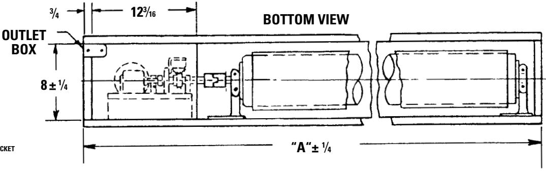
NOTE: Screen is not centered in box. Screen surface is set 18^5/8 from motor end.
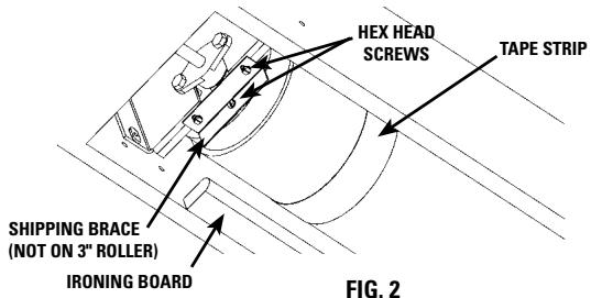
IRONING BOARD
Some Senior Electrons, depending on size and type of picture surface, contain an ironing board to flatten the fabric (long strip attached). The ironing board is part of the screen. Do not remove or alter (Fig. 2).
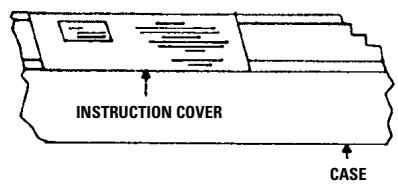
FIG.1
INSTALLATION
HANGERS (If required)
- Make sure one hanger is approximately 25^ from end of case (motor end).
- Make sure second hanger is approximately 11 12 from opposite end of case.
- Place a third hanger on the center line of fabric.
- Make sure hangers are placed to fit into notches provided on screens equipped with an ironing board.
- Make sure hanger used on motor end does not interfere with motor access door.
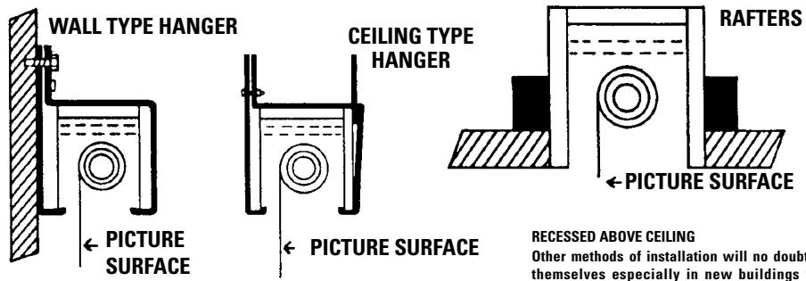
FOR EXPOSED INSTALLATION
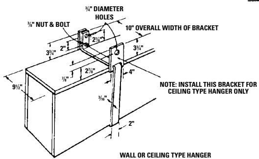
WALL OR CEILING MOUNT WITH HANGERS
Wall Type Hangers with ceiling hanger adapters are standard equipment. For wall type, use wall hanger only. For ceiling type installation, use the wall type hanger and ceiling adapters as shown in Fig. 3 on page 3.
RECESSED ABOVE CEILING
Other methods of installation will no doubt suggest themselves especially in new buildings where it would be an easy matter to provide a recess for the screen to conceal it when not in use. DO NOT SEAL IN-ALLOW ACCESS.
If the screen is to be mounted in an exposed position, it may be covered with finished plywood, veneer paneling, plastic wall covering or a valance.
INSTALLATION
- Level unit lengthwise with a carpenter's level and plum level.

CAUTION! DO NOT COMPLETELY SEAL IN UNIT. ACCESS ROOM MUST BE ALLOWED FOR MOTOR REPAIR OR FABRIC REPLACEMENT.
- Remove shipping brace by removing 3 hex head screws (Fig. 2).

CAUTION! DO NOT CUT WRAPPING PAPER OR TAPE WITH KNIFE OR ANY SHARP TOOL. REMOVE BY HAND.
- Remove wrapping paper and tape strips (Fig. 2).
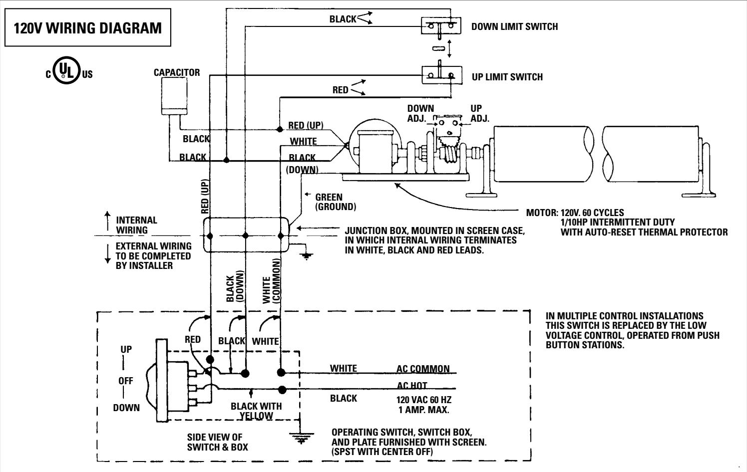
- Install electrical hook up that applies to your unit. Make sure to review your Electrical Installation Checklists and wiring diagrams (included) for either 120 volt switch, 220/240 volt switch, or DRC low voltage control. Unit should be wired by a qualified electrician.
- Test installation by carefully running surface up and down several times. Be prepared to stop screen.
- Check for satisfactory condition by running screen a few times.
NOTE: The picture surface, when rolled down, should have a full wrap around the roller. Do not allow any part of the roller to become exposed.
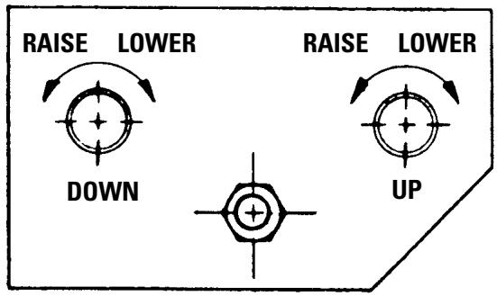
SCREEN ADJUSTMENT
Surface travel is stopped automatically in the fully opened and closed positions by limit switches that are properly adjusted at Da-Lite. Should it be necessary to adjust for more or less drop of picture (viewing area), proceed in the following manner:
MORE SCREEN DROP
- Place operating switch in "down" position.
- When the screen stops, turn the "down" limit knob one-quarter turn clockwise.
- Test by raising picture surface approximately two feet, then lower again. Repeat until desired drop is attained.

CAUTION! When screen is in bottom position, do not adjust for more than 3^ of additional drop. Roller should not be exposed.
LESS SCREEN DROP
- Raise picture surface approximately two feet above desired level.
- Place operating switch in "off" position.
- Turn the "down" limit knob one-quarter turn counterclockwise.
- Test by raising and lowering picture surface.
- Repeat steps 3 and 4 until desired drop is attained.
NOTE: Limit "down" switch knob controls stopping point of picture surface in bottom position. Limit "up" switch knob controls stopping point of picture surface inside case.
PICTURE SURFACE ROLLED UP OR CLOSED POSITION
NOTE: Adjustments should not be necessary to screen in the rolled up or closed position. If necessary, use the following procedures:
PICTURE SURFACE ROLLSTOOFARINTOCASE
- Lower picture surface approximately two feet with operating switch.
- Place operating switch in "off" position.
- Turn the "up" limit knob one-quarter turn clockwise.
- Press operating switch to raise picture surface. Repeat operation if picture surface continues to roll too far into case.
PICTURE SURFACE DOES NOT ROLL COMPLETELY INTO CASE
- Place operating switch in "up" position.
- Turn the "up" limit knob one-quarter turn counterclockwise.
- Test by lowering picture surface approximately two feet with operating switch, then raise picture. Repeat operation if desired position is not reached.
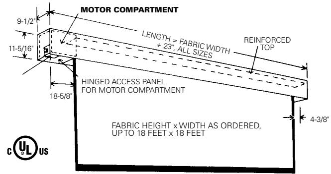
FOR SCREENS UP TO 18' X 18'
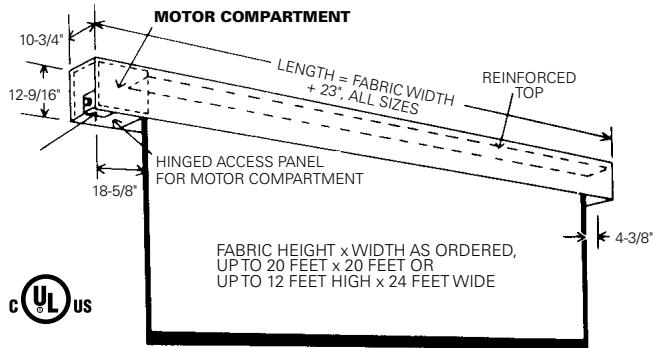
FOR SCREENS 20' AND LARGER IN HEIGHT OR WIDTH
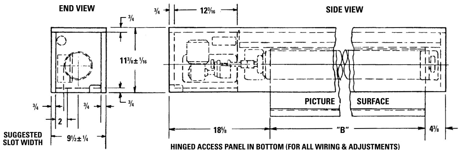
LENGTH A=FABRIC WIDTH "B" PLUS 23" ALL SIZES
FIG. 3
240 VOLT WIRING DIAGRAM
FOR STANDARD WALL SWITCH:
Da-Lite offers two styles of 240 volt wall
switches for standard operation. Please
see wiring diagram included in wall
switch box included with screen.
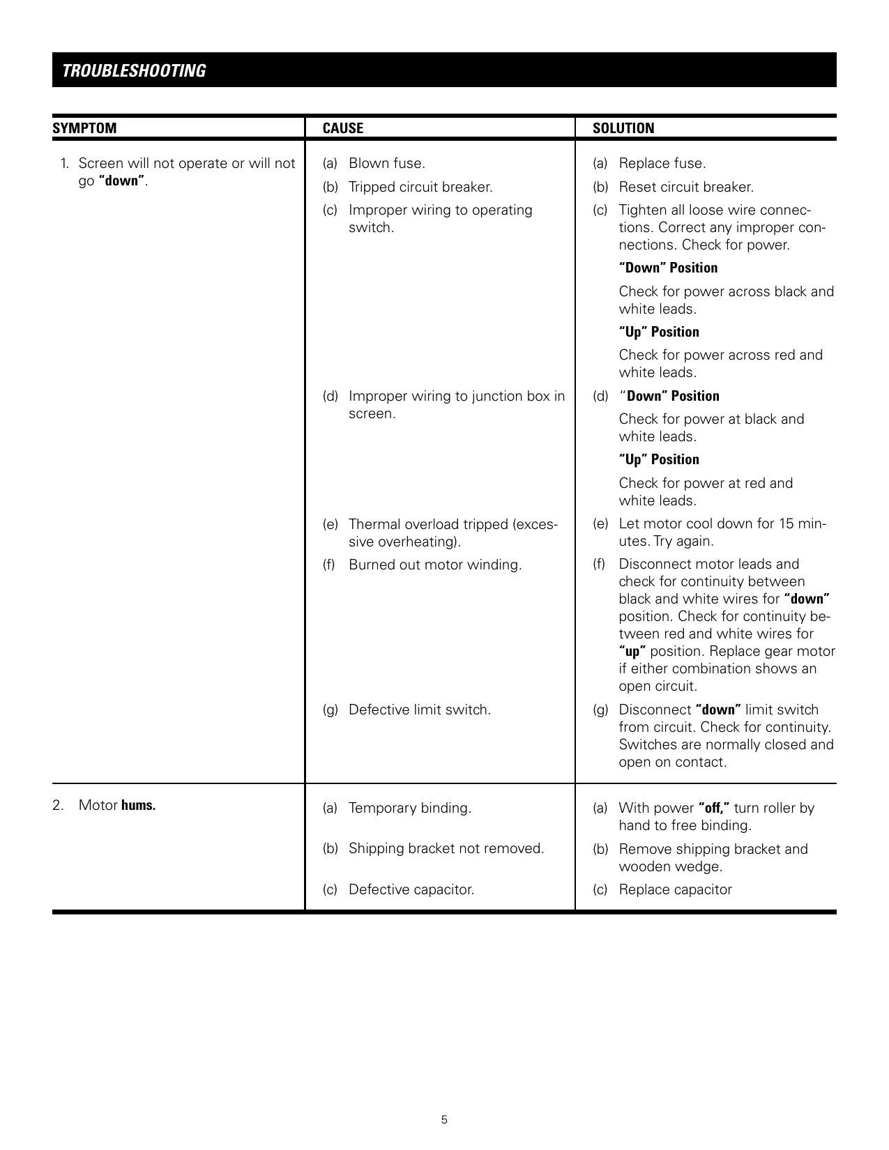
TROUBLESHOOTING
| SYMPTOM | CAUSE | SOLUTION |
| 1. Screen will not operate or will not go "down". | (a) Blown fuse.(b) Tripped circuit breaker.(c) Improper wiring to operating switch.(d) Improper wiring to junction box in screen.(e) Thermal overload tripped (excessive overheating).(f) Burned out motor winding.(g) Defective limit switch. | (a) Replace fuse.(b) Reset circuit breaker.(c) Tighten all loose wire connec-tions. Correct any improper con-nectons. Check for power."Down" PositionCheck for power across black and white leads."Up" PositionCheck for power across red and white leads.(d)"Down" PositionCheck for power at black and white leads."Up" PositionCheck for power at red and white leads.(e) Let motor cool down for 15 min-utes. Try again.(f) Disconnect motor leads and check for continuity between black and white wires for "down" position. Check for continuity be-tween red and white wires for "up" position. Replace gear motor if either combination shows an open circuit.(g) Disconnect "down" limit switch from circuit. Check for continuity. Switches are normally closed and open on contact. |
| 2. Motor hums. | (a) Temporary binding.(b) Shipping bracket not removed.(c) Defective capacitor. | (a) With power "off," turn roller by hand to free binding.(b) Remove shipping bracket and wooden wedge.(c) Replace capacitor |
TROUBLESHOOTING
| SYMPTOM | CAUSE | SOLUTION |
| 3. Screen will not move "up."Motor does not hum.Motor hums. | (a) Blown fuse or tripped circuit breaker.(b) No power between red and white leads in junction box.(c) Thermal overload tripped.(d) Burned out motor winding.(e) Temporary binding.(f) Burned out capacitor.(g) Broken wire or loose connection in "up" position circuit. | (a) Replace fuse or reset circuit breaker.(b) Correct improper wiring.(c) Let motor cool for 15 minutes. Try again.(d) Check for power between red and white motor leads. Replace motor if there is power.(e) With power off, turn roller by hand to free binding.(f) Replace capacitor.(g) Secure connection or replace wire. |
| 4. Scraping or grinding noise. | (a) If metal shipping bracket is left attached to screen, it may be rubbing on motor end of roller. | (a) Remove shipping bracket. |
| 5. Gear noise. | (a) Gear may need lubrication. | (a) Apply grease. |
| 6. Fabric rubbing. | (a) Normal condition.NOTE: Screens with ironing boards have fabric that drags across the board. | |
| 7. Incorrect stopping point in upward position. | (a) Lost roller wrap.(b) Limit switch out of adjustment. | (a) Lift bottom edge up and over roller.(b) See installation instructions. |
| 8. Incorrect stopping point in downward direction. | (a) Lost roller wrap.(b) Limit switch out of adjustment. | (a) See above.(b) See installation instructions. |
TROUBLESHOOTING
| SYMPTOM | CAUSE | SOLUTION |
| 9. Inconsistent stopping points. | (a) Limit switch travel plate not mov-ing. | (a) Tighten set screws located on nylon gears (drives limit switch). |
| (b) Excessive end play in lead screw of limit switch assembly. | (b) Tighten nut between adjusting knobs. Tighten lead screw of limit switch. | |
| 10. Screen does not stop going up or down. | (a) Limit switch assembly paddle damaged or is out of place. | (a) Remove and check limit switch assembly. Repair or replace as necessary. |
- The Da-Lite Difference.
- IMPORTANT SAFETY INSTRUCTIONS
- SAVE THESE INSTRUCTIONS
- PRE-INSTALLATION
- IRONING BOARD
- INSTALLATION
- HANGERS (If required)
- SCREEN ADJUSTMENT
- MORE SCREEN DROP
- LESS SCREEN DROP
- PICTURE SURFACE ROLLED UP OR CLOSED POSITION
- PICTURE SURFACE ROLLSTOOFARINTOCASE
- PICTURE SURFACE DOES NOT ROLL COMPLETELY INTO CASE
- VOLT WIRING DIAGRAM
- FOR STANDARD WALL SWITCH:
- TROUBLESHOOTING
Brand : DA-LITE
Model : SENIOR ELECTROL
Category : Electric projection screen