
COSMOPOLITAN ELECTROL - Electric projection screen DA-LITE - Free user manual and instructions
Find the device manual for free COSMOPOLITAN ELECTROL DA-LITE in PDF.
| Product type | Electric projection screen |
| Brand | DA-LITE |
| Model | COSMOPOLITAN ELECTROL |
| Maximum dimensions | Up to 9' x 12' (approx. 2.74 m x 3.66 m) |
| Overall length | Screen width + 8 inches (20.3 cm) |
| Mounting hole distance | Screen width + 6.5 inches (16.5 cm) |
| Weight | Varies by size (not specified) |
| Power supply | 120 VAC / 60 Hz or 220-240 VAC / 50/60 Hz depending on version |
| Power consumption | Not specified (standard) |
| Mounting modes | Wall (flush), ceiling suspended, flush ceiling mount |
| Motor | Electric with adjustable limit switches |
| Control | SPDT wall switch with center OFF; optional low-voltage control or projector interface |
| Duty cycle | 1 minute on / 3 minutes off |
| Screen surface | Rolled on roller, matte or beaded finish (depending on model) |
| Travel adjustment | Limit screws (standard models) or touch buttons (LVC/VPI models) |
| Safety | Automatic shut-off at end of travel, motor thermal protection |
| Maintenance | Clean with a soft, dry cloth; do not use harsh chemicals |
| Warranty | 1 year parts and labor (subject to conditions) |
| Standards | Compliant with local building codes, NEC, CEC |
| Country of origin | United States (American brand) |
Frequently Asked Questions - COSMOPOLITAN ELECTROL DA-LITE
User questions about COSMOPOLITAN ELECTROL DA-LITE
0 question about this device. Answer the ones you know or ask your own.
Ask a new question about this device
Download the instructions for your Electric projection screen in PDF format for free! Find your manual COSMOPOLITAN ELECTROL - DA-LITE and take your electronic device back in hand. On this page are published all the documents necessary for the use of your device. COSMOPOLITAN ELECTROL by DA-LITE.
USER MANUAL COSMOPOLITAN ELECTROL DA-LITE
The Da-Lite Difference.

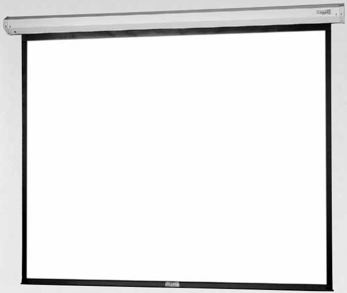
Instruction Book for COSMOPOLITAN® ELECTROL® For Sizes Up To 9'x12'

DA-LITE SCREEN COMPANY, INC.
3100 North Detroit Street
Post Office Box 137
Warsaw, Indiana 46581-0137
Phone: 574-267-8101
800-622-3737
Fax: 574-267-7804
Toll Free Fax: 877-325-4832
www.da-lite.com
e-mail: info@da-lite.com
IMPORTANT SAFETY INSTRUCTIONS
When using your video equipment, basic safety precautions should always be followed, including the following:
- Read and understand all instructions before using.
- Position the cord so that it will not be tripped over, pulled, or contact hot surfaces.
- If an extension cord is necessary, a cord with a current rating at least equal to that of the appliance should be used. Cords rated for less amperage than the appliance may overheat.
- To reduce the risk of electric shock, do not disassemble this appliance. Contact an authorized service dealer when repair work is required. Incorrect reassembly can cause electric shock when the appliance is used subsequently.
- The use of an accessory attachment not recommended by the manufacturer may cause a risk of fire, electric shock, or injury to persons.
SAVE THESE INSTRUCTIONS
PRE-INSTALLATION
- Carefully unpack screen and remove outer wrapping from case.
- Do not remove black tape or rubber bands from slat pocket.
- Always handle screen in horizontal position.
INSTALLATION
There are three methods of mounting to include:
Flush against wall; Suspended from ceiling (use extension brackets); and Recessed above ceiling.
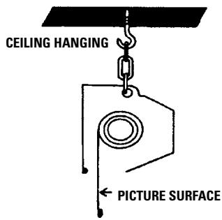
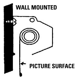
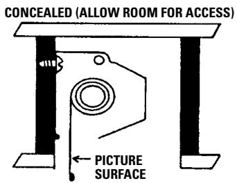
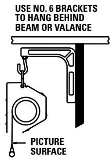
FIGURE 1
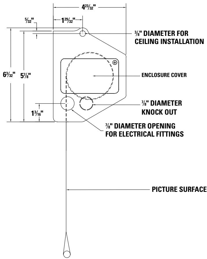
NOTE: Under no circumstances should unit be completely sealed in recessed installation. Allow access for service. Picture surface is centered in case. Case extends 4^ beyond surface on either end. Do not attach anything to screen slat rod or bottom fabric pocket.
- Make sure screen is level. Use a carpenter's level and plumb level.

CAUTION! Do not cut wrapping paper or tape with knife or any sharp tool. Remove by hand.
- Remove tape and rubber bands from slat pocket.
- Install electrical hook up that applies to your unit. Make sure to review your Electrical Installation Checklists and wiring diagrams (included) for either 120 volt switch, 220/240 volt switch, or low voltage control.
- Test installation by running screen up and down a few times. Be prepared to stop screen. Standard Duty Cycle: 1 MIN. ON / 3 MIN. OFF.
NOTE: Must be installed in accordance with the requirements of the Local Building Codes, the Canadian Electrical Code (CEC), CAN/ CSA C22.1 and the National Electric Code (NEC), NFPA 70.
COSMOPOLITAN ELECTROL INSTALLATION
3/4" DIAMETER HOLE FOR WALL INSTALLATION
Overall length A=fabric width + 8". Length B is the distance between wall mounting holes at back of end caps and is the fabric width + 6-1/2".
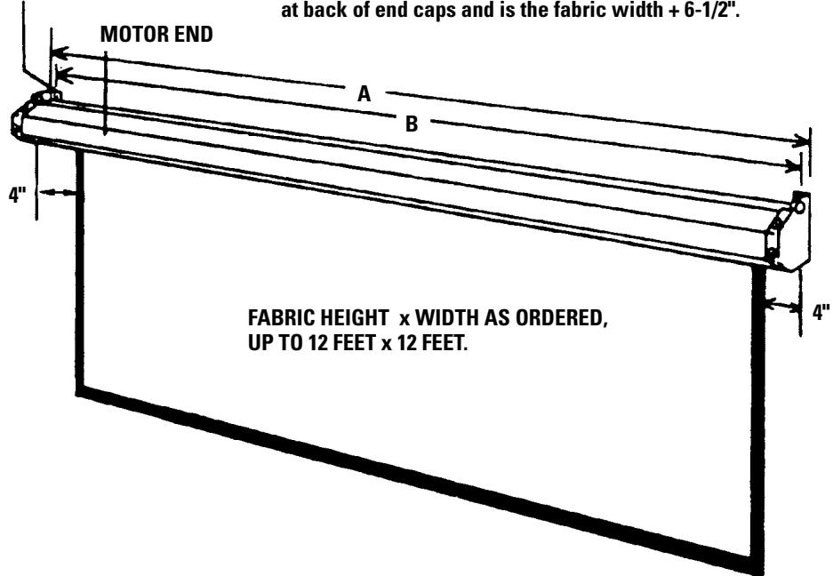
FIGURE 2
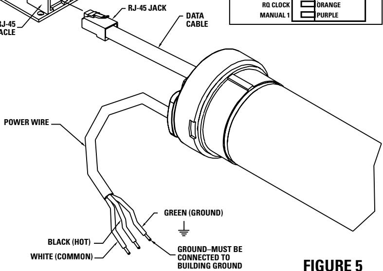
120V WIRING DIAGRAM

TO JUNCTION BOX, MOUNTED IN SCREEN CASE, IN WHICH INTERNAL WIRING TERMINATES IN WHITE, BLACK AND RED LEADS.
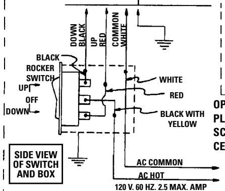
FIGURE 3
OPERATING SWITCH AND PLATE FURNISHED WITH SCREEN. (SPDT WITH CENTER OFF)
VIRING ENCLOSURE COVER
DOWN WHITE LIMIT SWITCH ADJUSTMEN
IN MULTIPLE CONTROL INSTALLATIONS
THIS SWITCH IS REPLACED BY THE LOW VOLTAGE CONTROL, OPERATED FROM PUSH BUTTON STATIONS.
THIS SWITCH CANNOT BE USED WITH LVC.
NOTE: A single switch cannot be used to operate more than one screen. Contact the factory for further information.
240 VOLT WIRING DIAGRAM FOR STANDARD WALL SWITCH:
Da-Lite offers two styles of 240 volt wall switches for standard operation. Please see wiring diagram included in wall switch box included with screen.
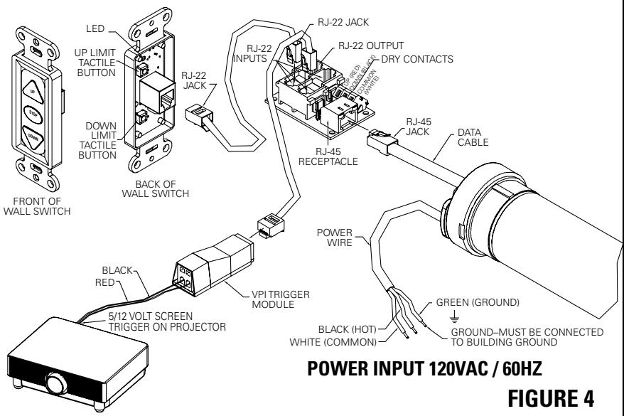
120V WIRING DIAGRAM WITH OPTIONAL BUILT-IN VIDEO PROJECTOR INTERFACE
CAUTION: THE PROJECTOR MUST BE TURNED OFF BEFORE CONNECTING THE TRIGGER WIRES TO THE PROJECTOR. FAILURE TO DO SO MAY DAMAGE THE CONTROLLER.
Use 2-conductor 20-24 gauge wire to extend the low voltage connection from the projector's 5 or 12-volt screen trigger output to the length required to reach the VPI. When extending the low voltage connection from the projector's screen trigger output polarity does not matter. The red and black wires from the VPI are interchangeable.
IMPORTANT NOTE:
The wall switch is REQUIRED to make any limit switch adjustments, EVEN if a third party control system is used. Therefore, it is advised to wire the switch or provide a 3-conductor connection that is accessible.
120V WIRING DIAGRAM WITH OPTIONAL BUILT-IN LOW VOLTAGE CONTROL
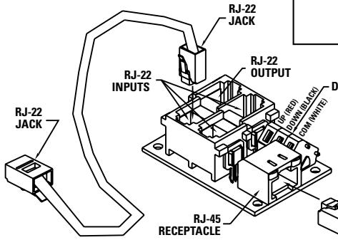
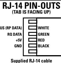
RJ-22 PIN-OUTS (TAB IS FACING UP)
Standard RJ-22 can be used in place of RJ-14
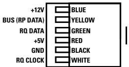
RJ-45 PIN-OUTS (TAB IS FACING UP)
IMPORTANT NOTE:
The wall switch is REQUIRED to make any limit switch adjustments, EVEN if a third party control system is used. Therefore, it is advised to wire the switch or provide a 3-conductor connection that is accessible.
POWER INPUT 120VAC / 60HZ
240V WIRING DIAGRAM WITH OPTIONAL BUILT-IN LOW VOLTAGE CONTROL
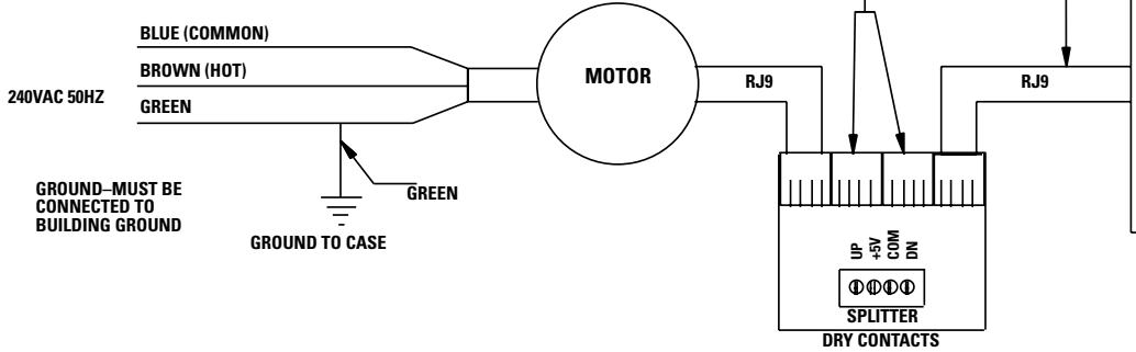
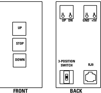
LOW-VOLTAGE WALL SWITCH

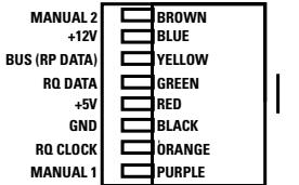
ILT RJ9 PIN-OUTS (TAB IS FACING UP)
IMPORTANT NOTE: The wall switch is REQUIRED to make any limit switch adjustments, EVEN if a third party control system is used. Therefore, it is advised to wire the switch or provide a 4-conductor connection that is accessible.
FIGURE 6
SCREEN ADJUSTMENT FOR SCREENS WITHOUT A BUILT-IN LOW VOLTAGE CONTROL
Surface travel is stopped automatically in the fully opened and closed positions by limit switches that are properly adjusted at DA-LITE. Should it be necessary to adjust for more or less picture drop (viewing area), proceed in the following manner:
NOTE: Use a screwdriver or 5/32" Allen wrench to make adjustments.
SETTING THE DOWN LIMIT POSITION
TO REDUCE SCREEN DROP:
Turn the white limit switch screw (Figure 3) clockwise to decrease the amount of screen drop. Run the screen down to test the stop position. If the screen drops too far, raise the screen about one foot and adjust the limit switch again. Repeat until the desired position is set.
TO INCREASE SCREEN DROP:
Turn the white limit switch screw counterclockwise to increase the amount of screen drop. Run the screen down to test the stop position. If the screen does not drop enough, raise the screen about one foot and adjust the limit switch again. Repeat until the desired position is set. Do not adjust for more drop than what was ordered. At least 1-1/2 wraps of fabric must remain on the roller.
CAUTION: Do not adjust for more drop than what was ordered. At least 1-1/2 wraps of fabric must remain on the roller. This screen comes standard with 0'' or 2'' black at the top. See the specification data sheet for details.
SCREEN ADJUSTMENT FOR 120V SCREENS WITH A BUILT-IN LOW VOLTAGE CONTROL OR VPI
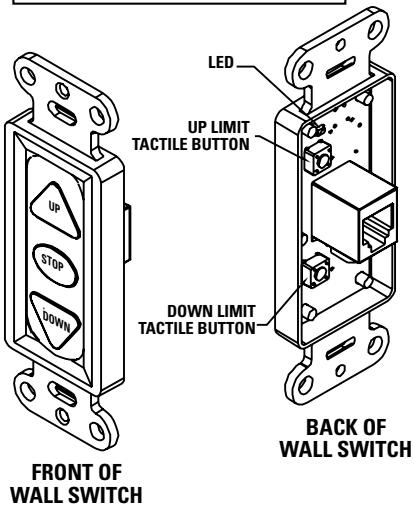
- Locate the wall switch and remove the cover plate from the 3-button wall switch and remove the switch from the junction box.
- Locate the two tactile buttons on the back of the switch. They are square silver with black round buttons. See Figure 4 (VPI) or Figure 5 (LVC) for diagram.
- To adjust the down limit switch, press and hold the down tactile button until the LED on back of switch turns solid red. This will put the motor in limit set mode. Turn the wall switch over and use the down button on front of switch. Press and hold until the desired travel position is reached. If you travel to far down you can press the up to move the screen upward. If you press and let go of either up or down button the motor will do a small jog in that direction for finer adjustment of screen. Once desired position is reached turn switch over press and hold down tactile button until the LED on back of switch blinks red twice. The down limit is now set.
- To adjust the up limit switch, press and hold the up tactile button until the LED on back of switch turns solid green. This will put the motor in limit set mode. Turn the wall switch over and use the up button on front of switch. Press and hold until the desired travel position is reached. If you travel to far up you can press the down to move the screen downward. If you press and let go of either up or down button the motor will do a small jog in that direction for finer adjustment of screen. Once desired position is reached turn switch over press and hold up tactile button until the LED on back of switch blinks green twice. The up limit is now set.
- To test limit switch setting, press and release the up or down button on the wall switch to operate the screen.
- Replace switch and cover plate on the wall.
IMPORTANT NOTE: The wall switch is REQUIRED to make any limit switch adjustments, EVEN if a third party control system is used. Therefore, it is advised to wire the switch or provide a 3-conductor connection that is accessible.
SCREEN ADJUSTMENT FOR 220V/240V SCREENS WITH A BUILT-IN LOW VOLTAGE CONTROL
- Remove the cover plate from the 3-button wall switch and remove the switch from the junction box.
- Locate small 3-position switch on back of wall switch. (See Figure 6)
- To adjust the down limit switch, slide the 3-position switch to the down position. Press and hold the down button to run the screen down to the desired stop position. Release the button to stop the screen. DO NOT PUSH THE STOP BUTTON.
- When the screen is in the desired down position, slide the 3-position switch to the off (center) position. The down limit switch is now set.
- To adjust the up limit switch, slide the 3-position switch to the up position. Press and hold the up button to run the screen up to the desired stop position. Release the button to stop the screen. DO NOT PUSH THE STOP BUTTON.
- When the screen is in the desired up position, slide the 3-position switch to the off (center) position. The up limit switch is now set.
- To test limit switch setting, make sure the 3-position switch is in the off (center) position. Press and release the up or down button on the wall switch to operate the screen.
- Replace switch and cover plate on the wall.
NOTE: If stop button is pressed, the wall switch will reverse direction. To correct this, press the stop button again. This will reset the switch. You will have to re-set both the up and the down settings.
IMPORTANT NOTE: The wall switch is REQUIRED to make any limit switch adjustments, EVEN if a third party control system is used. Therefore, it is advised to wire the switch or provide a 4-conductor connection that is accessible.
| SYMPTOM | CAUSE | SOLUTION |
| 1. Screen will not operate.Motor does not hum. | (a) Incorrect line voltage.(b) Blown fuse.(c) Tripped circuit breaker.(d) No power to operating switch or junction. | (a) Verify 115-125V (or 220-240V). If insufficient voltage, rewire incoming electric line.(b) Replace fuse.(c) Reset circuit breaker.(d) Check above. Tighten all loose wire connections. Correct any improper connections.“Down” PositionCheck for power across black and white leads.“Up” PositionCheck for power across red and white leads. |
| Motor hums. | Power at junction box(e) Thermal overload tripped.(f) Broken wire in the “up” or “down” position.(g) Defective motor, limit switch or capacitor.(h) Capacitor burned out. | (e) Let motor cool down for 15 minutes. Try again.(f) Check for continuity. Cut off old splice and reconnect.(g) Replace motor assembly.NOTE: Motor is a sealed assembly.(h) Replace motor assembly. |
| 2. Incorrect stopping position in downward direction. | (a) Lost roller wrap.(b) “Down” limit switch out of adjustment | (a) See instructions below.(b) See installation instructions. |
| 3. Incorrect stopping position in upward direction. | (a) Lost roller wrap.(b) “Up” limit switch out of adjustment | (a) See instructions below.(b) Adjust “up” limit switch. Call factory for instructions |
| 4. Noise.NOTE: Screen will operate with a low pitched hum. | (a) Gear noise. | (a) Replace motor assembly. |
| 5. Coasting. | (a) Defective brake. | (a) Replace motor assembly. |
| 6. Roller displaced from mounting bracket. | (a) Pin end slipped out of nylon bearing. | (a) Realign pin end bracket. |
RESTORING LOST ROLLER WRAP
- Push strap over back of roller.
- Tape end of strap to pocket.
- Feed fabric as you pull strap to draw fabric over top.
- Remove tape and strap.
LIMITED ONE YEAR WARRANTY ON DA-LITE PRESENTATION PRODUCTS
Da-Lite Screen Company, Inc. warrants its products to the original purchaser only, to be free from defects in materials and workmanship for a period of one (1) year from the date of purchase by the original purchaser provided they are properly operated according to Da-Lite's instructions and are not damaged due to improper handling or treatment after shipment from the factory.
This warranty does not apply to equipment showing evidence of misuse, abuse or accidental damage, or which has been tampered with or repaired by a person other than authorized Da-Lite personnel.
Da-Lite's sole obligation under this warranty shall be to repair or to replace (at Da-Lite's option) the defective part of the merchandise. Returns for service should be made to your Da-Lite dealer. If it is necessary for the dealer to return the screen or part to Da-Lite, transportation expenses to and from Da-Lite are payable by the purchaser and Da-Lite is not responsible for damage in shipment. To protect yourself against damage or loss in transit, insure the product and prepay all transportation expenses.
THIS WARRANTY IS IN LIEU OF ALL OTHER WARRANTYES, EXPRESS OR IMPLIED, INCLUDING WARRANTY AS TO FITNESS FOR USE AND MERCHANT ABILITY. Any implied warranties of fitness for use, or merchantability, that may be mandated by statute or rule of law are limited to the one (1) year warranty period. This warranty gives you specific legal rights, and you may also have other rights, which vary from state-to-state. NO LIABILITY IS ASSUMED FOR EXPENSES OR DAMAGES RESULTING FROM INTERRUPTION IN OPERATION OF EQUIPMENT, OR FOR INCIDENTAL, DIRECT, OR CONSEQUENTIAL DAMAGES OF ANY NATURE.
In the event that there is a defect in materials or workmanship of a Da-Lite product, you may contact our Sales Partners at PO Box 137, Warsaw, IN 46581-0137, (574) 267-8101, (800) 622-3737.
IMPORTANT: THIS WARRANTY SHALL NOT BE VALID AND DA-LITE SHALL NOT BE BOUND BY THIS WARRANTY IF THE PRODUCT IS NOT OPERATED IN ACCORDANCE WITH DA-LITE'S WRITTEN INSTRUCTIONS.
Keep your sales receipt to prove the date of purchase and your original ownership.
- The Da-Lite Difference.
- IMPORTANT SAFETY INSTRUCTIONS
- SAVE THESE INSTRUCTIONS
- PRE-INSTALLATION
- INSTALLATION
- COSMOPOLITAN ELECTROL INSTALLATION
- 120V WIRING DIAGRAM
- THIS SWITCH CANNOT BE USED WITH LVC.
- VOLT WIRING DIAGRAM FOR STANDARD WALL SWITCH:
- 120V WIRING DIAGRAM WITH OPTIONAL BUILT-IN VIDEO PROJECTOR INTERFACE
- CAUTION: THE PROJECTOR MUST BE TURNED OFF BEFORE CONNECTING THE TRIGGER WIRES TO THE PROJECTOR. FAILURE TO DO SO MAY DAMAGE THE CONTROLLER.
- IMPORTANT NOTE:
- 120V WIRING DIAGRAM WITH OPTIONAL BUILT-IN LOW VOLTAGE CONTROL
- 240V WIRING DIAGRAM WITH OPTIONAL BUILT-IN LOW VOLTAGE CONTROL
- SCREEN ADJUSTMENT FOR SCREENS WITHOUT A BUILT-IN LOW VOLTAGE CONTROL
- SETTING THE DOWN LIMIT POSITION
- SCREEN ADJUSTMENT FOR 120V SCREENS WITH A BUILT-IN LOW VOLTAGE CONTROL OR VPI
- SCREEN ADJUSTMENT FOR 220V/240V SCREENS WITH A BUILT-IN LOW VOLTAGE CONTROL
- RESTORING LOST ROLLER WRAP
- LIMITED ONE YEAR WARRANTY ON DA-LITE PRESENTATION PRODUCTS
Brand : DA-LITE
Model : COSMOPOLITAN ELECTROL
Category : Electric projection screen