
TENSIONED ADVANTAGE ELECTROL - Projection screen DA-LITE - Free user manual and instructions
Find the device manual for free TENSIONED ADVANTAGE ELECTROL DA-LITE in PDF.
User questions about TENSIONED ADVANTAGE ELECTROL DA-LITE
0 question about this device. Answer the ones you know or ask your own.
Ask a new question about this device
Download the instructions for your Projection screen in PDF format for free! Find your manual TENSIONED ADVANTAGE ELECTROL - DA-LITE and take your electronic device back in hand. On this page are published all the documents necessary for the use of your device. TENSIONED ADVANTAGE ELECTROL by DA-LITE.
USER MANUAL TENSIONED ADVANTAGE ELECTROL DA-LITE
The Da-Lite Difference.

Instruction Book for
TENSIONED ADVANTAGE® ELECTROL®

DA-LITE SCREEN COMPANY, INC.
3100 North Detroit Street
Post Office Box 137
Warsaw, Indiana 46581-0137
Phone: 574-267-8101
800-622-3737
Fax: 574-267-7804
Toll Free Fax: 877-325-4832
www.da-lite.com
e-mail: info@da-lite.com
IMPORTANT SAFETY INSTRUCTIONS
When using your video equipment, basic safety precautions should always be followed, including the following:
- Read and understand all instructions before using.
- Position the cord so that it will not be tripped over, pulled, or contact hot surfaces.
- If an extension cord is necessary, a cord with a current rating at least equal to that of the appliance should be used. Cords rated for less amperage than the appliance may overheat.
- To reduce the risk of electric shock, do not disassemble this appliance. Contact an authorized service dealer when repair work is required. Incorrect reassembly can cause electric shock when the appliance is used subsequently.
- The use of an accessory attachment not recommended by the manufacturer may cause a risk of fire, electric shock, or injury to persons.
SAVE THESE INSTRUCTIONS
PRE-INSTALLATION
- Carefully unpack case from shipping carton. DO NOT unpack fabric and roller assembly yet.
- Make sure to recheck measurement of case for proper installation clearance.
- Remove any protective foam or tape from case.
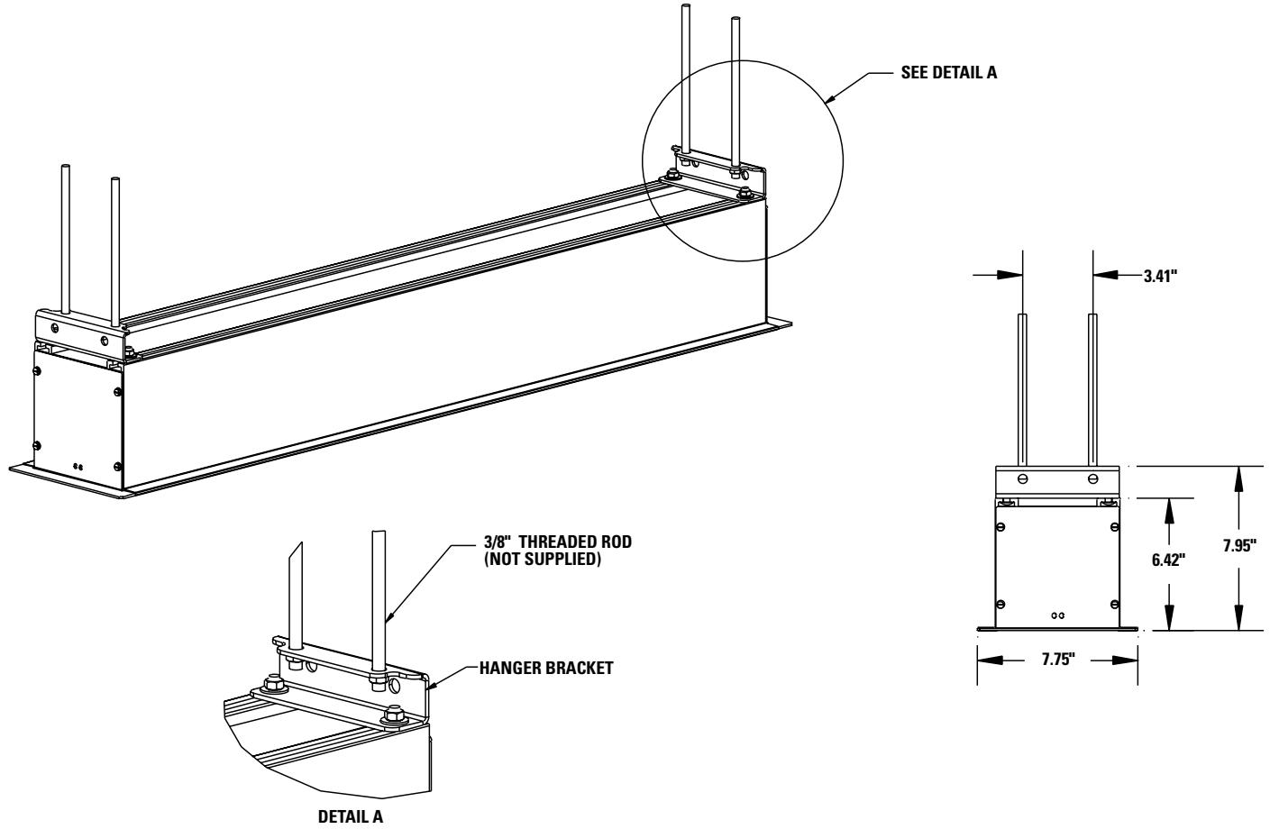
CASE INSTALLATION
- Remove 2 screws to open junction box.
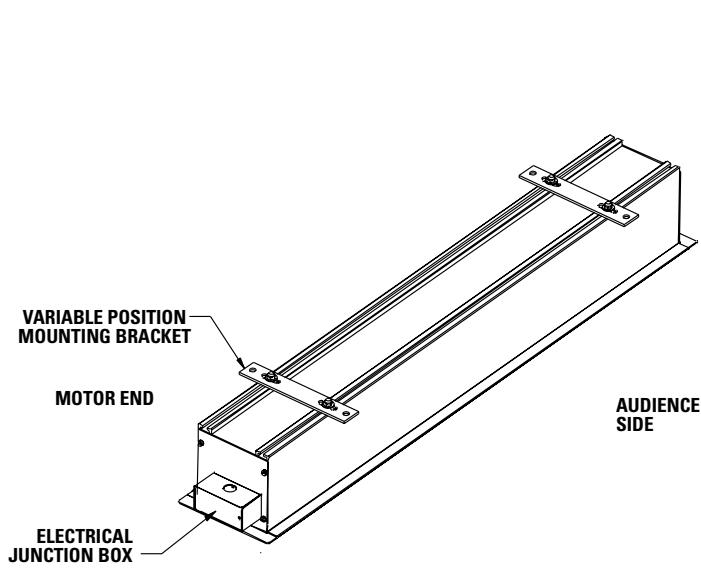
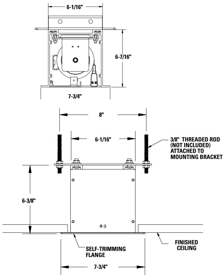
- Hang case and attach to support structure with threaded rod. See suggested methods of installation on page 5.
- Tighten bolts until trim flange is flush with ceiling.
NOTE: For proper operation, screen assembly must be level after installation.
- Install electrical connections that applies to your unit. Make sure to review the wiring diagram for proper hook up.
NOTE: Must be installed in accordance with the requirements of the Local Building Codes, the Canadian Electrical Code (CEC), CAN/CSA C22.1 and the National Electric Code (NEC), NFPA 70. - Replace junction box cover and secure with 2 screws.
- If screen and case are purchased together, remove slat retainer brackets from the screen case and back of slat.
SCREEN AND ROLLER ASSEMBLY INSTALLATION
If your screen was shipped with the motor and roller already installed, proceed to step 6.
- Remove access door. First, remove the 2 screws from the ends. Be sure to support the door during this step to avoid injury. Then lift the door slightly and pull away from the edge of the case.
- Carefully unpack screen and roller assembly. Leave packing paper on roller.
- To install screen and roller assembly, insert the motor end into the motor mount bracket as shown in Fig. 1.
- Loosen (but do not remove) two 1/4-20 nuts securing pin end bracket (stage left) to the case housing. Slide the bracket towards the end of the case. Insert the motor end square shaft into the motor end bracket and secure with the clip.Insert the tip of the roller pin end into the bracket and position. Tighten the 1/4-20 nuts securely.
- Complete electrical hook-up by snapping motor wire connector into case connector.
- Carefully remove paper and tape from roller assembly. DO NOT use a knife or sharp object to cut tape; you will damage the screen.
- Test installation by running screen up and down a few times. Be prepared to stop screen. Standard Duty Cycle: 1 MIN. ON / 3 MIN. OFF.
- Re-install access door. Procedure is reverse of removal (step 1).
120V WIRING DIAGRAM FOR STANDARD WALL SWITCH
JUNCTION BOX
LOCATED IN
LEFTENDCAP
NOTE: A SINGLE SWITCH CANNOT BE USED TO OPERATE MORE THAN ONE SCREEN. CONTACT THE FACTORY FOR FURTHER INFORMATION.
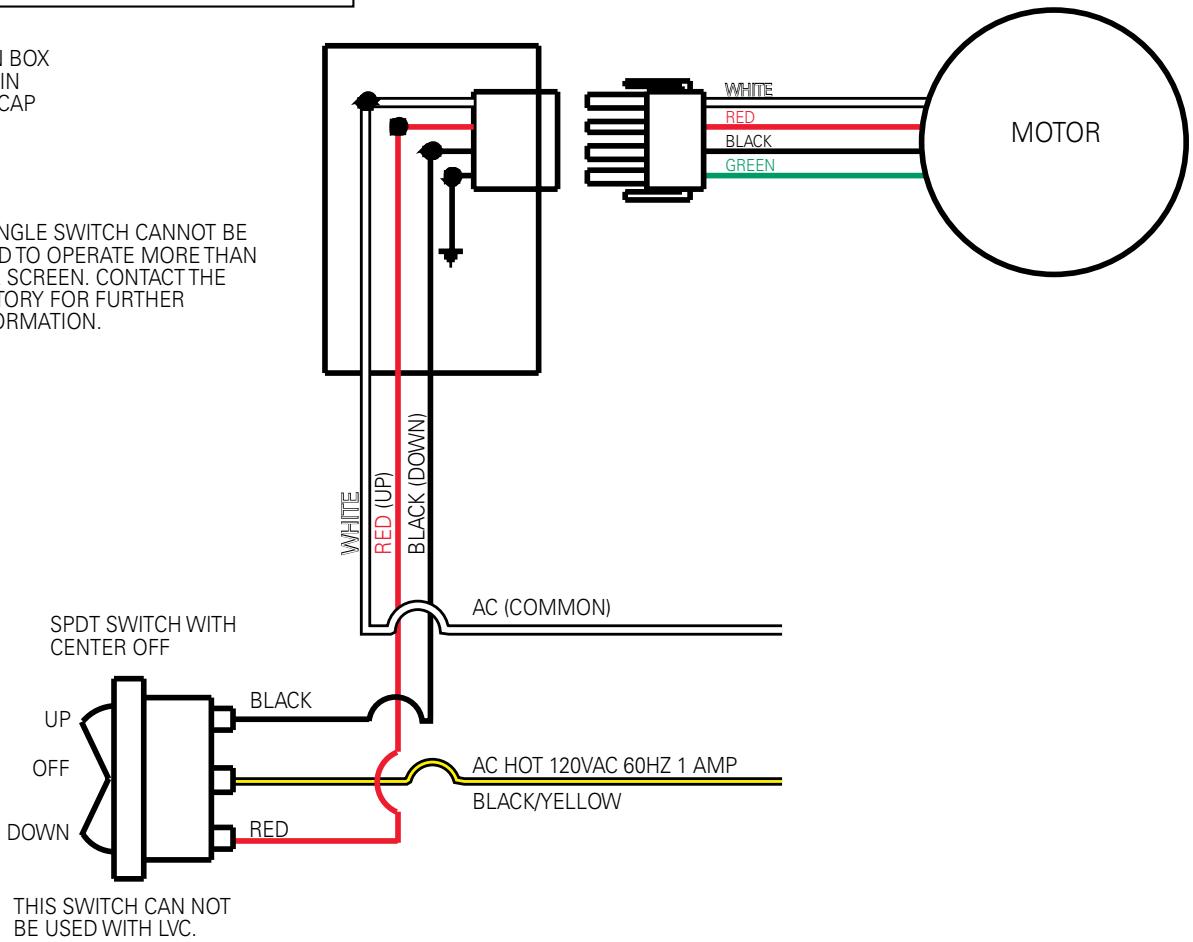
FIGURE 3
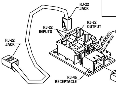
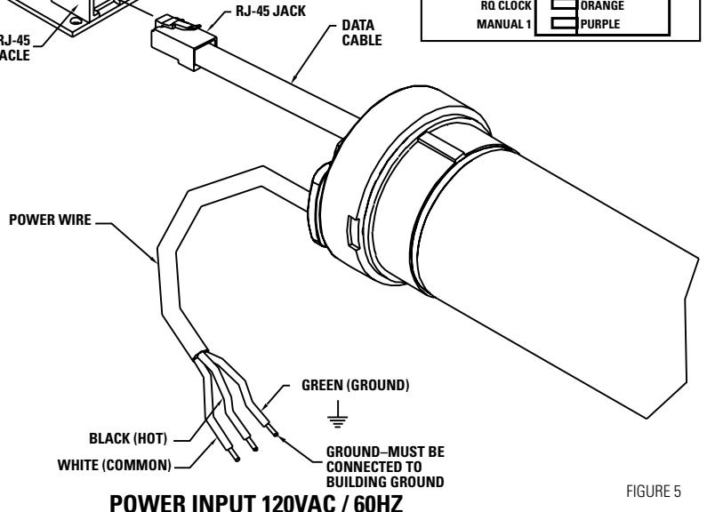
120V WIRING DIAGRAM WITH OPTIONAL BUILT-IN VIDEO PROJECTOR INTERFACE
CAUTION: THE PROJECTOR MUST BE TURNED OFF BEFORE CONNECTING THE TRIGGER WIRES TO THE PROJECTOR. FAILURE TO DO SO MAY DAMAGE THE CONTROLLER.
Use 2-conductor 20-24 gauge wire to extend the low voltage connection from the projector's 5 or 12-volt screen trigger output to the length required to reach the VPI. When extending the low voltage connection from the projector's screen trigger output polarity does not matter. The red and black wires from the VPI are interchangeable.
IMPORTANT NOTE:
The wall switch is REQUIRED to make any limit switch adjustments, EVEN if a third party control system is used. Therefore, it is advised to wire the switch or provide a 3-conductor connection that is accessible.
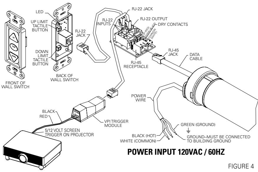
FIGURE 4
120V WIRING DIAGRAM WITH OPTIONAL BUILT-IN LOW VOLTAGE CONTROL
IMPORTANT NOTE:
The wall switch is REQUIRED to make any limit switch adjustments, EVEN if a third party control system is used. Therefore, it is advised to wire the switch or provide a 3-conductor connection that is accessible.
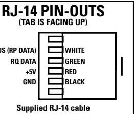
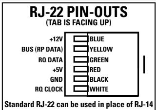
RJ-22 PIN-OUTS
(TAB IS FACING UP)
| +12V | BLUE |
| BUS (RP DATA) | YELLOW |
| RQ DATA | GREEN |
| +5V | RED |
| GND | BLACK |
| RQ CLOCK | WHITE |
Standard RJ-22 can be used in place of RJ-14
RJ-45 PIN-OUTS
(TAB IS FACING UP)
| MANUAL 2 | BROWN |
| +12V | BLUE |
| BUS (RP DATA) | YELLOW |
| RQ DATA | GREEN |
| +5V | RED |
| GND | BLACK |
| RQ CLOCK | ORANGE |
| MANUAL 1 | PURPLE |
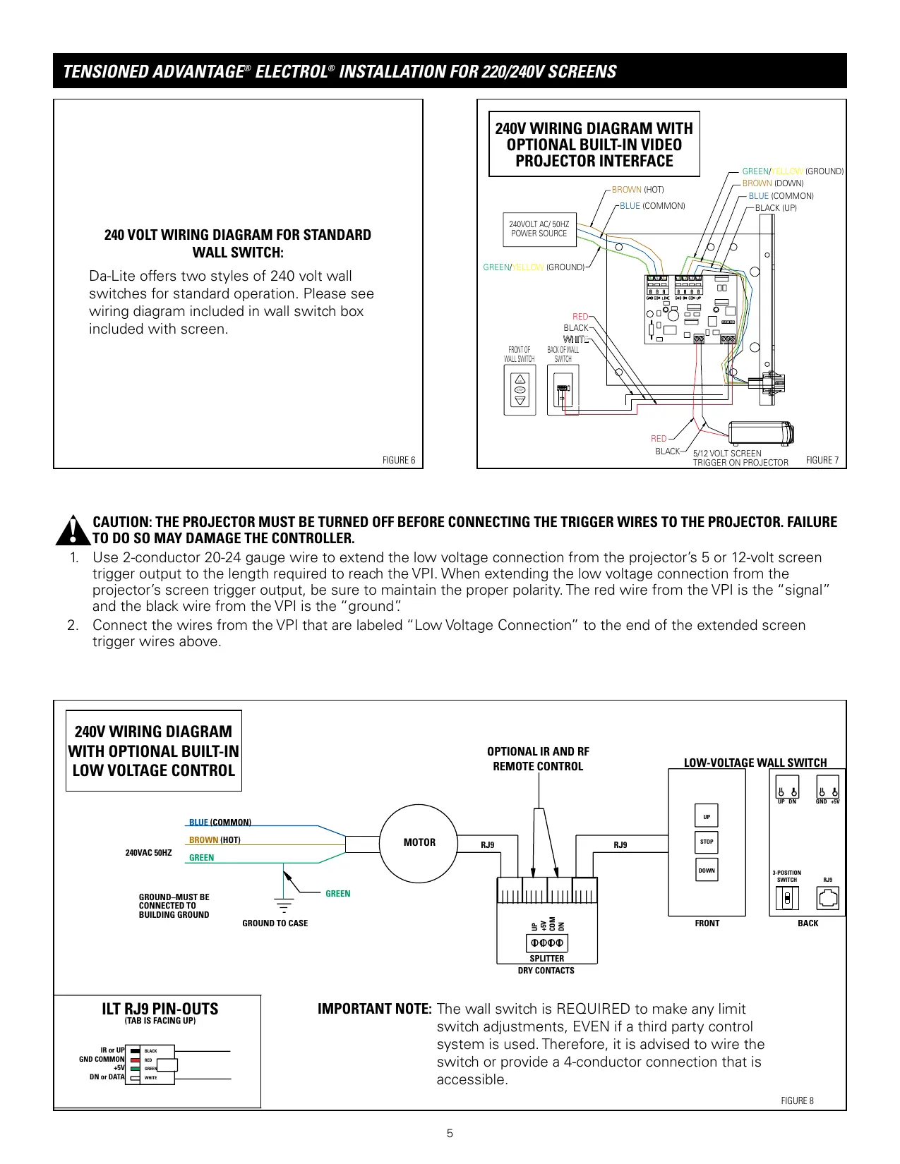
240 VOLT WIRING DIAGRAM FOR STANDARD WALL SWITCH:
Da-Lite offers two styles of 240 volt wall switches for standard operation. Please see wiring diagram included in wall switch box included with screen.
FIGURE 6
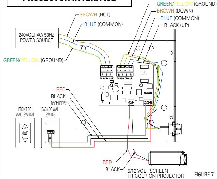
240V WIRING DIAGRAM WITH OPTIONAL BUILT-IN VIDEO PROJECTOR INTERFACE

CAUTION: THE PROJECTOR MUST BE TURNED OFF BEFORE CONNECTING THE TRIGGER WIRES TO THE PROJECTOR. FAILURE TO DO SO MAY DAMAGE THE CONTROLLER.
- Use 2-conductor 20-24 gauge wire to extend the low voltage connection from the projector's 5 or 12-volt screen trigger output to the length required to reach the VPI. When extending the low voltage connection from the projector's screen trigger output, be sure to maintain the proper polarity. The red wire from the VPI is the "signal" and the black wire from the VPI is the "ground."
- Connect the wires from the VPI that are labeled "Low Voltage Connection" to the end of the extended screen trigger wires above.
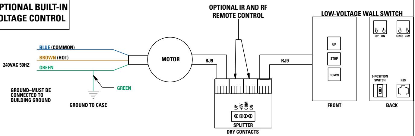
240V WIRING DIAGRAM WITH OPTIONAL BUILT-IN LOW VOLTAGE CONTROL

ILT RJ9 PIN-OUTS (TAB IS FACING UP)
IMPORTANT NOTE: The wall switch is REQUIRED to make any limit switch adjustments, EVEN if a third party control system is used. Therefore, it is advised to wire the switch or provide a 4-conductor connection that is accessible.
FIGURE 8
SCREEN ADJUSTMENT FOR 120V SCREENS WITHOUT BUILT-IN LOW VOLTAGE CONTROL
Surface travel is stopped automatically in the fully opened and closed positions by limit switches that are properly adjusted at Da-Lite. Should it be necessary to adjust for more or less drop of picture, proceed in the following manner: Remove two screws to remove access door.
NOTE: Use a screw driver or 5/32" Allen wrench to make adjustments.
MORE SCREEN DROP
- Place operating switch in "down" position.
- When the screen stops, turn the white "down" limit knob (Fig.1) one turn counterclockwise. Test by raising picture surface approximately two feet, then lower again. Repeat until desired picture surface position is attained.
LESS SCREEN DROP
- Raise picture surface approximately two feet above desired level.
- Place operating switch in "off" position.
- Turn the white "down" limit knob (Fig. 1) one turn clockwise. Test by raising picture surface approximately two feet, then lower again. Repeat until desired picture surface position is attained.
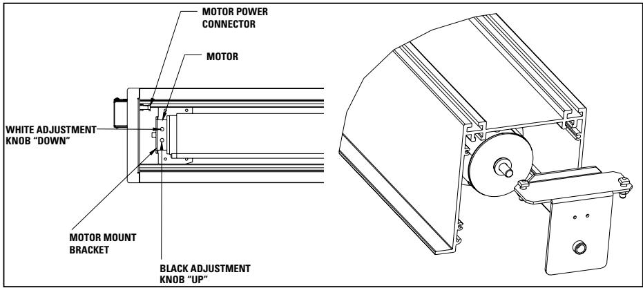
FIGURE 1
SCREEN ADJUSTMENT FOR 220/240V SCREENS WITHOUT BUILT-IN LOW VOLTAGE CONTROL
Surface travel is stopped automatically in the fully opened and closed positions by limit switches that are properly adjusted at Da-Lite. Should it be necessary to adjust for more or less drop of picture, proceed in the following manner:
NOTE: Use a screw driver or 5/32" Allen wrench to make adjustments.
MORE SCREEN DROP
- Place operating switch in "down" position.
- When the screen stops, turn the white "down" limit knob (Fig.2) one turn counterclockwise. Test by raising picture surface approximately two feet, then lower again. Repeat until desired picture surface position is attained.
LESS SCREEN DROP
- Raise picture surface approximately two feet above desired level.
- Place operating switch in "off" position.
- Turn the white "down" limit knob (Fig. 2) one turn clockwise. Test by raising picture surface approximately two feet, then lower again. Repeat until desired picture surface position is attained.
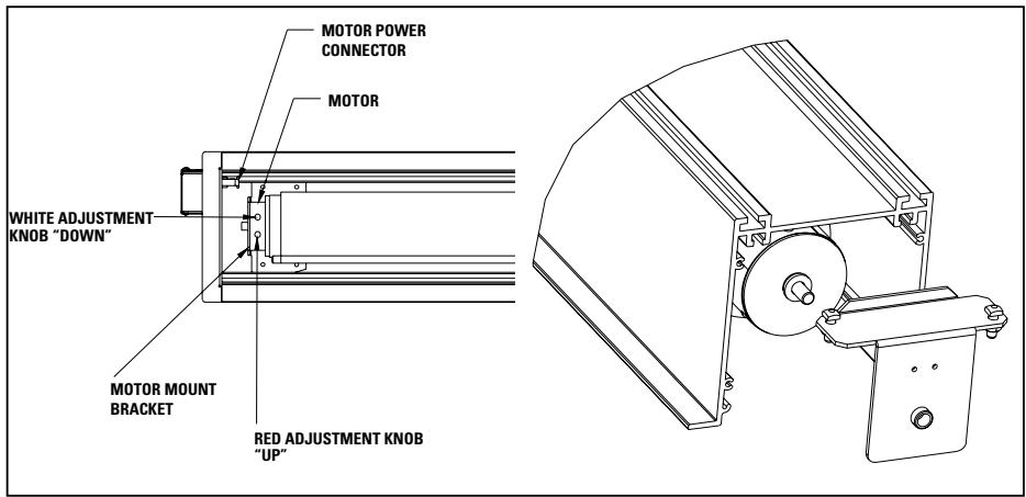
FIGURE 2
SCREEN ADJUSTMENT FOR 120V SCREENS WITH A BUILT-IN LOW VOLTAGE CONTROL OR VPI
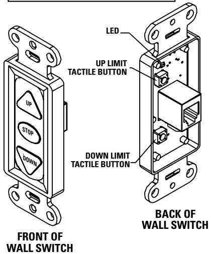
- Locate the wall switch and remove the cover plate from the 3-button wall switch and remove the switch from the junction box.
- Locate the two tactile buttons on the back of the switch. They are square silver with black round buttons. See Figure 4 (VPI) or Figure 5 (LVC) for diagram.
- To adjust the down limit switch, press and hold the down tactile button until the LED on back of switch turns solid red. This will put the motor in limit set mode. Turn the wall switch over and use the down button on front of switch. Press and hold until the desired travel position is reached. If you travel to far down you can press the up to move the screen upward. If you press and let go of either up or down button the motor will do a small jog in that direction for finer adjustment of screen. Once desired position is reached turn switch over press and hold down tactile button until the LED on back of switch blinks red twice. The down limit is now set.
- To adjust the up limit switch, press and hold the up tactile button until the LED on back of switch turns solid green. This will put the motor in limit set mode. Turn the wall switch over and use the up button on front of switch. Press and hold until the desired travel position is reached. If you travel to far up you can press the down to move the screen downward. If you press and let go of either up or down button the motor will do a small jog in that direction for finer adjustment of screen. Once desired position is reached turn switch over press and hold up tactile button until the LED on back of switch blinks green twice. The up limit is now set.
- To test limit switch setting, press and release the up or down button on the wall switch to operate the screen.
- Replace switch and cover plate on the wall.
IMPORTANT NOTE: The wall switch is REQUIRED to make any limit switch adjustments, EVEN if a third party control system is used. Therefore, it is advised to wire the switch or provide a 3-conductor connection that is accessible.
SCREEN ADJUSTMENT FOR 220V/240V SCREENS WITH A BUILT-IN LOW VOLTAGE CONTROL
- Remove the cover plate from the 3-button wall switch and remove the switch from the junction box.
- Locate small 3-position switch on back of wall switch. See Figure 5 for 120V screens or Figure 8 for 220/240V screens.
- To adjust the down limit switch, slide the 3-position switch to the down position. Press and hold the down button to run the screen down to the desired stop position. Release the button to stop the screen. DO NOT PUSH THE STOP BUTTON.
- When the screen is in the desired down position, slide the 3-position switch to the off (center) position. The down limit switch is now set.
- To adjust the up limit switch, slide the 3-position switch to the up position. Press and hold the up button to run the screen up to the desired stop position. Release the button to stop the screen. DO NOT PUSH THE STOP BUTTON.
- When the screen is in the desired up position, slide the 3-position switch to the off (center) position. The up limit switch is now set.
- To test limit switch setting, make sure the 3-position switch is in the off (center) position. Press and release the up or down button on the wall switch to operate the screen.
- Replace switch and cover plate on the wall.
NOTE: If stop button is pressed, the wall switch will reverse direction. To correct this, press the stop button again. This will reset the switch. You will have to re-set both the up and the down limit settings.
IMPORTANT NOTE: The wall switch is REQUIRED to make any limit switch adjustments, EVEN if a third party control system is used. Therefore, it is advised to wire the switch or provide a 4-conductor connection that is accessible.
| SYMPTOM | CAUSE | SOLUTION |
| 1. Screen will not operate.Motor does not hum. | (a) Incorrect line voltage.(b) Blown fuse.(c) Tripped circuit breaker.(d) No power to operating switch or junction.Power at junction box(e) Thermal overload tripped.(f) Broken wire in the "down" or "up" position.(g) Defective motor, limit switch or capacitor.(h) Capacitor burned out. | (a) Verify 115-125V (or 220-240V). If insufficient voltage, rewire incoming electric line.(b) Replace fuse.(c) Reset circuit breaker.(d) Check above. Tighten all loose wire connections. Correct any improper connections."Down" PositionCheck for power across black and white leads."Up" PositionCheck for power across red and white leads.(e) Let motor cool down for 15 minutes. Try again.(f) Check for continuity. Cut off old splice and reconnect.(g) Replace motor assembly.NOTE: Motor is a sealed assembly.(h) Replace motor assembly. |
| 2. Screen does not stop at correct position. | (a) Limit switch out of adjustment. | (a) See Screen Adjustment section. |
| 3. Noise.NOTE: Screen will operate with a low-pitched hum. | (a) Squeaking, rubber end plug rubbing on motor.(b) Grinding. Foreign object in screen rubbing on roller or fabric.(c) Gear noise. | (a) Center roller in case.(b) Remove.(c) Replace motor assembly. |
| 4. Coasting. | (a) Defective brake. | (a) Replace motor assembly. |
| 5. Fabric hangs crooked. | (a) Screen not installed properly.(b) Fabric has backed up inside case.(c) Fabric is damaged. | (a) Check for level and plumb.(b) Adjust "down" limit switch slowly until roller is exposed and wrinkle comes out, then readjust for proper drop.(c) Replace fabric. |
LIMITED ONE YEAR WARRANTY ON DA-LITE PRESENTATION PRODUCTS
Da-Lite Screen Company, Inc. warrants its products to the original purchaser only, to be free from defects in materials and workmanship for a period of one (1) year from the date of purchase by the original purchaser provided they are properly operated according to Da-Lite's instructions and are not damaged due to improper handling or treatment after shipment from the factory.
This warranty does not apply to equipment showing evidence of misuse, abuse or accidental damage, or which has been tampered with or repaired by a person other than authorized Da-Lite personnel.
Da-Lite's sole obligation under this warranty shall be to repair or to replace (at Da-Lite's option) the defective part of the merchandise. Returns for service should be made to your Da-Lite dealer. If it is necessary for the dealer to return the screen or part to Da-Lite, transportation expenses to and from Da-Lite are payable by the purchaser and Da-Lite is not responsible for damage in shipment. To protect yourself against damage or loss in transit, insure the product and prepay all transportation expenses.
THIS WARRANTY IS IN LIEU OF ALL OTHER WARRANTYES, EXPRESS OR IMPLIED, INCLUDING WARRANTY AS TO FITNESS FOR USE AND MERCHANT ABILITY. Any implied warranties of fitness for use, or merchantability, that may be mandated by statute or rule of law are limited to the one (1) year warranty period. This warranty gives you specific legal rights, and you may also have other rights, which vary from state-to-state. NO LIABILITY IS ASSUMED FOR EXPENSES OR DAMAGES RESULTING FROM INTERRUPTION IN OPERATION OF EQUIPMENT, OR FOR INCIDENTAL, DIRECT, OR CONSEQUENTIAL DAMAGES OF ANY NATURE.
In the event that there is a defect in materials or workmanship of a Da-Lite product, you may contact our Sales Partners at PO Box 137, Warsaw, IN 46581-0137, (574) 267-8101, (800) 622-3737.
IMPORTANT: THIS WARRANTY SHALL NOT BE VALID AND DA-LITE SHALL NOT BE BOUND BY THIS WARRANTY IF THE PRODUCT IS NOT OPERATED IN ACCORDANCE WITH DA-LITE'S WRITTEN INSTRUCTIONS.
Keep your sales receipt to prove the date of purchase and your original ownership.