
CONTOUR ELECTROL - Projection screen DA-LITE - Free user manual and instructions
Find the device manual for free CONTOUR ELECTROL DA-LITE in PDF.
| Product Type | Motorized projection screen |
| Brand | DA-LITE |
| Model | CONTOUR ELECTROL |
| Supply voltage | 120 VAC or 240 VAC, 50/60 Hz |
| Power consumption | Approximately 100 W (depending on motor) |
| Standard duty cycle | 1 min run / 3 min stop |
| Mounting modes | Wall, ceiling or ceiling hook |
| Limit adjustments | Adjustable travel limits (up and down) |
| Control options | Standard wall switch, integrated projector interface (VPI) or low voltage control |
| Top black drop | 0 or 2 inches (standard) |
| Screen width | Varies by model (see spec sheet) |
| Drop height | Adjustable (minimum 1.5 turns of fabric on roller) |
| Fabric type | Standard projection fabric (not specified) |
| Safety features | Thermal cutoff, fuse, emergency stop via switch |
| Maintenance | Gentle cleaning with dry cloth, do not use abrasive products |
| Repairability | Spare parts available through authorized service (motor, switch, capacitor) |
| Warranty | Consult dealer or manufacturer |
| Electrical standards | Complies with NEC (NFPA 70) and CEC (CSA C22.1) |
| Accessories included | Wall brackets, ceiling brackets, wiring kit (depending on version) |
| Operating temperature | 10 °C to 40 °C (approx) |
| Housing dimensions | Varies with screen width (see spec sheet) |
| Weight | Varies with size |
| Manufacturer | DA-LITE Screen Company, Inc., Warsaw, Indiana, USA |
| Customer service | Phone 800-622-3737, email info@da-lite.com |
Frequently Asked Questions - CONTOUR ELECTROL DA-LITE
User questions about CONTOUR ELECTROL DA-LITE
0 question about this device. Answer the ones you know or ask your own.
Ask a new question about this device
Download the instructions for your Projection screen in PDF format for free! Find your manual CONTOUR ELECTROL - DA-LITE and take your electronic device back in hand. On this page are published all the documents necessary for the use of your device. CONTOUR ELECTROL by DA-LITE.
USER MANUAL CONTOUR ELECTROL DA-LITE
The Da-Lite Difference.

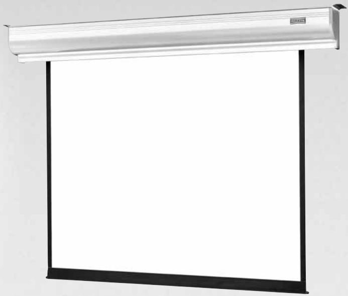
Instruction Book for CONTOUR® ELECTROL®

DA-LITE SCREEN COMPANY, INC.
3100 North Detroit Street
Post Office Box 137
Warsaw, Indiana 46581-0137
Phone: 574-267-8101
800-622-3737
Fax: 574-267-7804
Toll Free Fax: 877-325-4832
www.da-lite.com
e-mail: info@da-lite.com
IMPORTANT SAFETY INSTRUCTIONS
When using your video equipment, basic safety precautions should always be followed, including the following:
- Read and understand all instructions before using.
- Position the cord so that it will not be tripped over, pulled, or contact hot surfaces.
- If an extension cord is necessary, a cord with a current rating at least equal to that of the appliance should be used. Cords rated for less amperage than the appliance may overheat.
- To reduce the risk of electric shock, do not disassemble this appliance. Contact an authorized service dealer when repair work is required. Incorrect reassembly can cause electric shock when the appliance is used subsequently.
- The use of an accessory attachment not recommended by the manufacturer may cause a risk of fire, electric shock, or injury to persons.
SAVE THESE INSTRUCTIONS
INSTALLATION
Carefully unpack screen and remove outer wrapping from case.
Remove the black tape and rubber bands from the slat bar after the case has been installed.
There are three ways to install the Contour® Electrol®: Wall Mount, Ceiling Mount, or Ceiling Hook. Procedures for each method are as follows:
Wall Mount
- Secure the wall mount bracket to the wall at the desired height. Bracket should be fastened to wall studs or some reinforcement within the wall. Concrete or brick walls require special fasteners and anchors.
- Make sure the bracket is level. See figure 1 for reference dimensions.
- Keep in mind you will need at least 2 - 3 / 8" between the ceiling and the top of the wall mount bracket to be able to position the case on the bracket.
- Mount the screen case on the wall bracket as shown in figure 1. Be sure the case is fully seated on the bracket. Tighten the stop screws against the wall bracket.
Ceiling Mount
- Do not remove the wall mount bracket, even if you are not using it for mounting. This provides structural stability to the case.
- Be sure the ceiling has adequate reinforcement to attach the screen brackets.
- The top of the screen case has two channels with threaded nuts that slide the length of the case. Attach two ceiling mount brackets to the screen case as shown in figure 2. Mount cannot be more than 12" from end of case.
- Hold the screen case up to the ceiling and mark the hole locations. The brackets have a set of front holes and a set of rear holes. It is best to use at least one hole in each set.
Ceiling Hook
- Do not remove the wall mount bracket, even if you are not using it for mounting. This provides structural stability to the case.
- Be sure the ceiling has adequate reinforcement to attach a hook anchor.
- The top of the screen case has two channels with threaded nuts that slide the length of the case. Attach ceiling hook brackets as provided to the screen case as shown in figure 3.
- The brackets can be attached anywhere within 12'' of the end of the case.
- Attach an S-hook or similar fastener to the hole in the bracket.
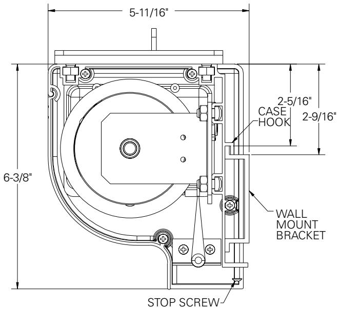
FIGURE 1
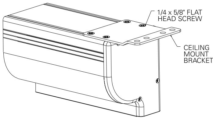
FIGURE 2
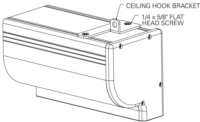
FIGURE 3
ELECTRICAL INSTALLATION
Internal wiring has been completed at the factory. Installer must route power to the wall switch and to the junction box located on the left end of the screen case.
Standard installation is for a single 120VAC or 240VAC wall switch to control the screen. Optional Control units may have been ordered. Wiring diagrams for the built-in VPI and low voltage control are included in these instructions. Refer to additional instructions for the external VPI, external low voltage control, SCB-100 and SCB-200. Refer to the appropriate wiring diagram for your screen.
Test installation by running screen up and down a few times. Be prepared to stop screen.
Standard Duty Cycle: 1MIN. ON / 3 MIN. OFF.
NOTE: Must be installed in accordance with the requirements of the Local Building Codes, the Canadian Electrical Code (CEC), CAN/ CSA C22.1 and the National Electric Code (NEC), NFPA 70.
SCREEN ADJUSTMENT FOR 120V AND 220V/240V SCREENS WITHOUT BUILT-IN LOW VOLTAGE CONTROL
Screen travel is stopped automatically in the down and up positions by the limit switches that are preset at the factory. If it's necessary to adjust for more or less drop follow the steps below. The case cover must be removed to access the motor limit switches.
Remove the case cover screw from both ends of the screen. See figures 4 and 5. Be sure to hold the cover while removing the screws.
Rotate the cover up and away from the case until it can be removed.
SETTING THE DOWN LIMIT POSITION
TO REDUCE SCREEN DROP:
Turn the white limit switch screw clockwise to decrease the amount of screen drop. Run the screen down to test the stop position. If the screen drops too far, raise the screen about one foot and adjust the limit switch again. Repeat until the desired position is set.
TO INCREASE SCREEN DROP:
Turn the white limit switch screw counterclockwise to increase the amount of screen drop. Run the screen down to test the stop position. If the screen does not drop enough, raise the screen about one foot and adjust the limit switch again. Repeat until the desired position is set.

CAUTION: Do not adjust for more drop than what was ordered. At least 1-1/2 wraps of fabric must remain on the roller. This screen comes standard with 0" or 2" black at the top. See the specification data sheet for details.
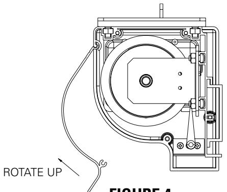
FIGURE 4
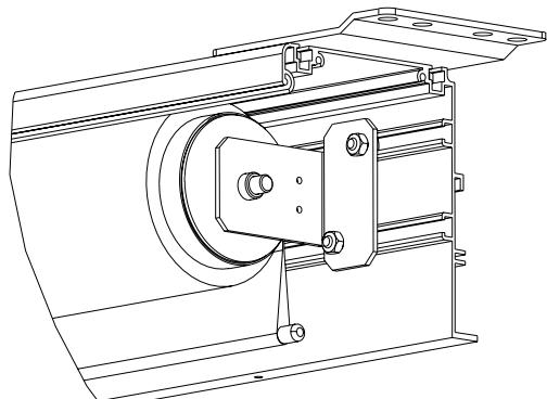
FIGURE 5
SCREEN ADJUSTMENT FOR 120V SCREENS WITH A BUILT-IN LOW VOLTAGE CONTROL OR VPI
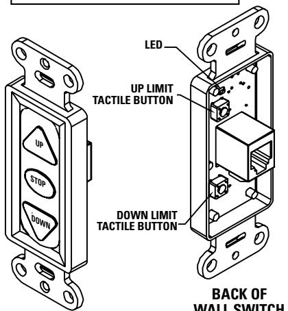
- Locate the wall switch and remove the cover plate from the 3-button wall switch and remove the switch from the junction box.
- Locate the two tactile buttons on the back of the switch. They are square silver with black round buttons. See Figure 8 (VPI) or Figure 10 (LVC) for diagram.
- To adjust the down limit switch, press and hold the down tactile button until the LED on back of switch turns solid red. This will put the motor in limit set mode. Turn the wall switch over and use the down button on front of switch. Press and hold until the desired travel position is reached. If you travel to far down you can press the up to move the screen upward. If you press and let go of either up or down button the motor will do a small jog in that direction for finer adjustment of screen. Once desired position is reached turn switch over press and hold down tactile button until the LED on back of switch blinks red twice. The down limit is now set.
- To adjust the up limit switch, press and hold the up tactile button until the LED on back of switch turns solid green. This will put the motor in limit set mode. Turn the wall switch over and use the up button on front of switch. Press and hold until the desired travel position is reached. If you travel to far up you can press the down to move the screen downward. If you press and let go of either up or down button the motor will do a small jog in that direction for finer adjustment of screen. Once desired position is reached turn switch over press and hold up tactile button until the LED on back of switch blinks green twice. The up limit is now set.
- To test limit switch setting, press and release the up or down button on the wall switch to operate the screen.
- Replace switch and cover plate on the wall.
IMPORTANT NOTE: The wall switch is REQUIRED to make any limit switch adjustments, EVEN if a third party control system is used. Therefore, it is advised to wire the switch or provide a 3-conductor connection that is accessible.
CAUTION: Do not adjust for more drop than what was ordered. At least 1-1/2 wraps of fabric must remain on the roller. This screen comes standard with 0'' or 2'' black at the top. See the specification data sheet for details.
SCREEN ADJUSTMENT FOR 220V/240V SCREENS WITH A BUILT-IN LOW VOLTAGE CONTROL
- Remove the cover plate from the 3-button wall switch and remove the switch from the junction box.
- Locate small 3-position switch on back of wall switch. (See Figure 11)
CAUTION: Do not adjust for more drop than what was ordered. At least 1-1/2 wraps of fabric must remain on the roller. This screen comes standard with 0'' or 2'' black at the top. See the specification data sheet for details.
- To adjust the down limit switch, slide the 3-position switch to the down position. Press and hold the down button to run the screen down to the desired stop position. Release the button to stop the screen. DO NOT PUSH THE STOP BUTTON.
- When the screen is in the desired down position, slide the 3-position switch to the off (center) position. The down limit switch is now set.
- To adjust the up limit switch, slide the 3-position switch to the up position. Press and hold the up button to run the screen up to the desired stop position. Release the button to stop the screen. DO NOT PUSH THE STOP BUTTON.
- When the screen is in the desired up position, slide the 3-position switch to the off (center) position. The up limit switch is now set.
- To test limit switch setting, make sure the 3-position switch is in the off (center) position. Press and release the up or down button on the wall switch to operate the screen.
- Replace switch and cover plate on the wall.
NOTE: If stop button is pressed, the wall switch will reverse direction. To correct this, press the stop button again. This will reset the switch. You will have to re-set both the up and the down settings.
IMPORTANT NOTE: The wall switch is REQUIRED to make any limit switch adjustments, EVEN if a third party control system is used. Therefore, it is advised to wire the switch or provide a 4-conductor connection that is accessible.
120V WIRING DIAGRAM FOR STANDARD WALL SWITCH
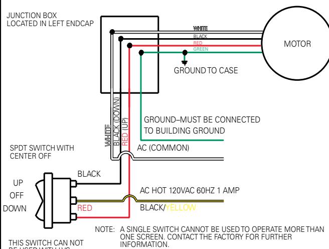
FIGURE 6
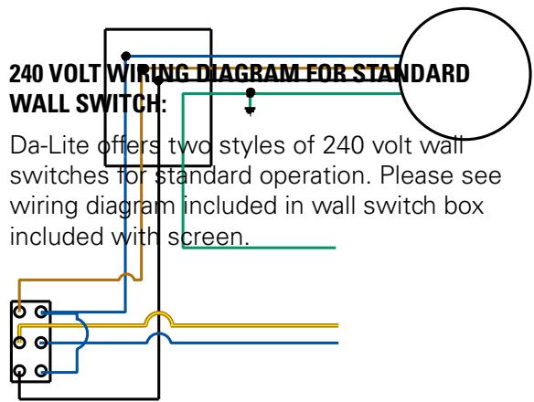
FIGURE 7
120V WIRING DIAGRAM WITH OPTIONAL BUILT-IN VIDEO PROJECTOR INTERFACE
CAUTION: THE PROJECTOR MUST BE TURNED OFF BEFORE CONNECTING THE TRIGGER WIRES TO THE PROJECTOR. FAILURE TO DO SO MAY DAMAGE THE CONTROLLER.
Use 2-conductor 20-24 gauge wire to extend the low voltage connection from the projector's 5 or 12-volt screen trigger output to the length required to reach the VPI. When extending the low voltage connection from the projector's screen trigger output polarity does not matter. The red and black wires from the VPI are interchangeable.
IMPORTANT NOTE:
The wall switch is REQUIRED to make any limit switch adjustments, EVEN if a third party control system is used. Therefore, it is advised to wire the switch or provide a 3-conductor connection that is accessible.
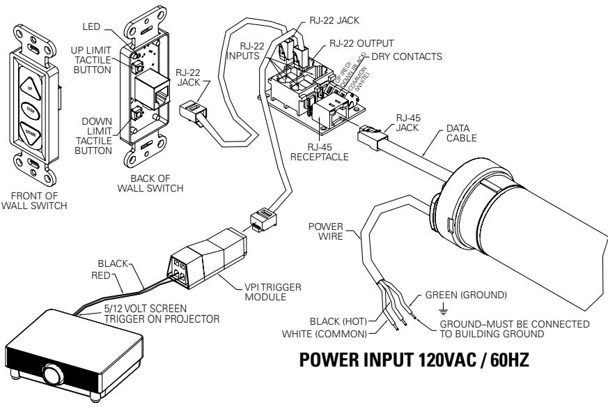
FIGURE 8
240V WIRING DIAGRAM WITH OPTIONAL BUILT-IN VIDEO PROJECTOR INTERFACE
CAUTION: THE PROJECTOR MUST BE TURNOED OFF BEFORE CONNECTING THE TRIGGER WIRES TO THE PROJECTOR. FAILURE TO DO SO MAY DAMAGE THE CONTROLLER.
- Use 2-conductor 20-24 gauge wire to extend the low voltage connection from the projector's 5 or 12-volt screen trigger output to the length required to reach the VPI. When extending the low voltage connection from the projector's screen trigger output, be sure to maintain the proper polarity. The red wire from the VPI is the "signal" and the black wire from the VPI is the "ground".
- Connect the wires from the VPI that are labeled "Low Voltage Connection" to the end of the extended screen trigger wires above.
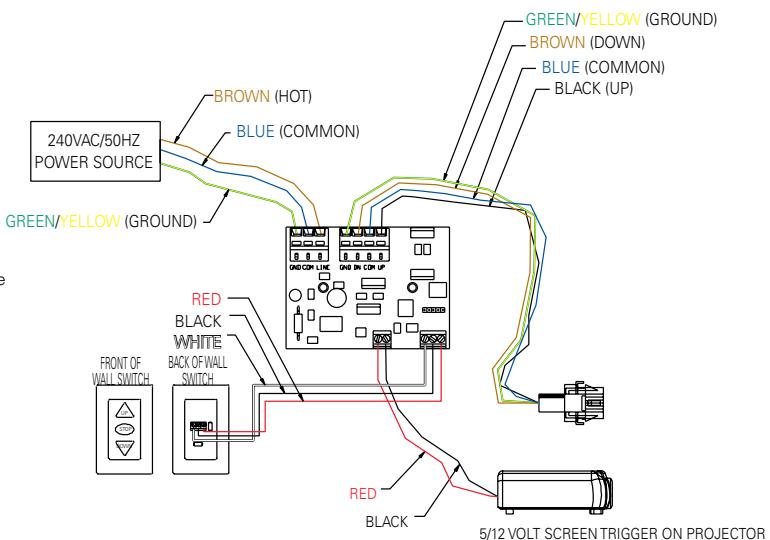
FIGURE 9
120V WIRING DIAGRAM WITH OPTIONAL BUILT-IN LOW VOLTAGE CONTROL
FRONT OF WALL SWITCH
IMPORTANT NOTE:
The wall switch is REQUIRED to make any limit switch adjustments, EVEN if a third party control system is used. Therefore, it is advised to wire the switch or provide a 3-conductor connection that is accessible.
POWER INPUT 120VAC / 60HZ
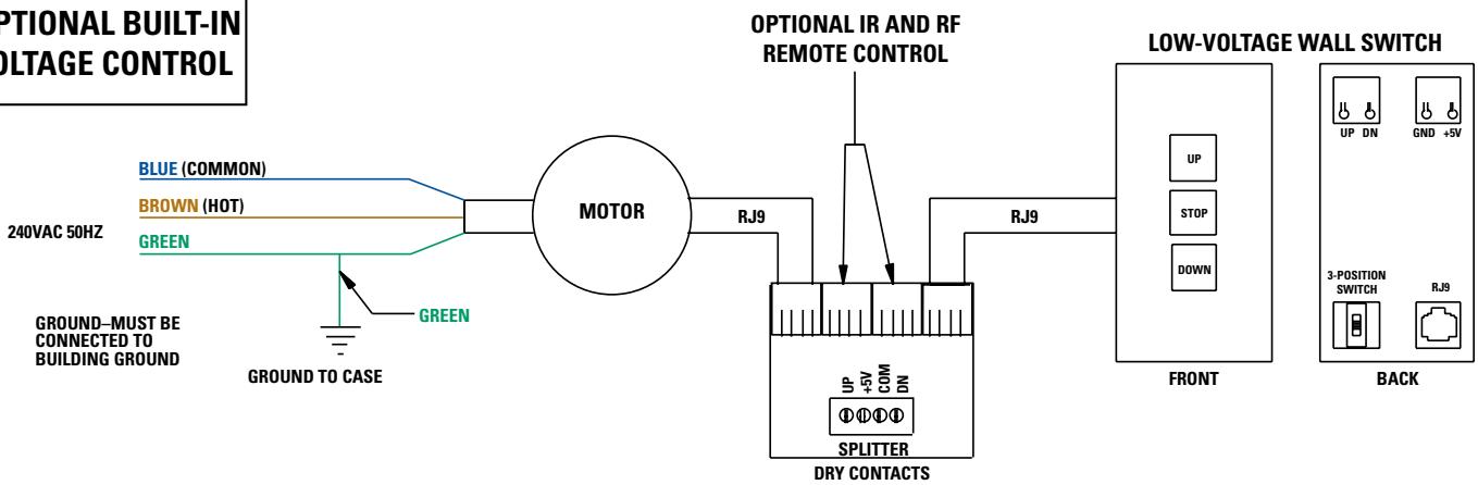
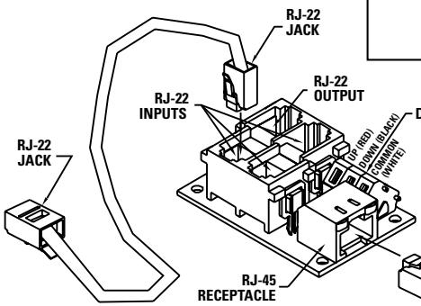
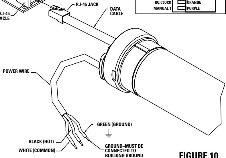
240V WIRING DIAGRAM WITH OPTIONAL BUILT-IN LOW VOLTAGE CONTROL
ILT RJ9 PIN-OUTS
(TAB IS FACING UP)

FIGURE 11
IMPORTANT NOTE: The wall switch is REQUIRED to make any limit switch adjustments, EVEN if a third party control system is used. Therefore, it is advised to wire the switch or provide a 4-conductor connection that is accessible.
TROUBLESHOOTING
| SYMPTOM | CAUSE | SOLUTION |
| 1. Screen will not operate.Motor does not hum. | (a) Incorrect line voltage.(b) Blown fuse.(c) Tripped circuit breaker.(d) No power to operating switch or junction.Power at junction box(e) Thermal overload tripped.(f) Broken wire in the "down" or "up" position.(g) Defective motor, limit switch or capacitor.(h) Capacitor burned out. | (a) Verify 115-125V (or 220-240V). If insufficient voltage, rewire incoming electric line.(b) Replace fuse.(c) Reset circuit breaker.(d) Check above. Tighten all loose wire connections. Correct any improper connections."Down" PositionCheck for power across black and white leads."Up" PositionCheck for power across red and white leads.(e) Let motor cool down for 15 minutes. Try again.(f) Check for continuity. Cut off old splice and reconnect.(g) Replace motor assembly.NOTE: Motor is a sealed assembly.(h) Replace motor assembly. |
| 2. Incorrect stopping position in downward direction. | (a) Lost roller wrap.(b) "Down" limit switch out of adjustment | (a) See instructions below.(b) See installation instructions. |
| 3. Incorrect stopping position in upward direction. | (a) Lost roller wrap.(b) "Up" limit switch out of adjustment | (a) See instructions below.(b) Adjust "up" limit switch. Call for information |
| 4. Noise.NOTE: Screen will operate with a low pitched hum. | (a) Gear Noise. | (a) Replace motor assembly. |
| 5. Coasting. | (a) Defective brake. | (a) Replace motor assembly. |
RESTORING LOST ROLLER WRAP
- Tape a strap to the bottom of the screen surface.
- Push strap over back of roller.
- Feed fabric as you pull strap to draw fabric over top of roller.
- Remove tape and strap.
- The Da-Lite Difference.
- DA-LITE SCREEN COMPANY, INC.
- IMPORTANT SAFETY INSTRUCTIONS
- SAVE THESE INSTRUCTIONS
- INSTALLATION
- Wall Mount
- Ceiling Mount
- Ceiling Hook
- ELECTRICAL INSTALLATION
- SCREEN ADJUSTMENT FOR 120V AND 220V/240V SCREENS WITHOUT BUILT-IN LOW VOLTAGE CONTROL
- SETTING THE DOWN LIMIT POSITION
- SCREEN ADJUSTMENT FOR 120V SCREENS WITH A BUILT-IN LOW VOLTAGE CONTROL OR VPI
- SCREEN ADJUSTMENT FOR 220V/240V SCREENS WITH A BUILT-IN LOW VOLTAGE CONTROL
- 120V WIRING DIAGRAM FOR STANDARD WALL SWITCH
- 120V WIRING DIAGRAM WITH OPTIONAL BUILT-IN VIDEO PROJECTOR INTERFACE
- CAUTION: THE PROJECTOR MUST BE TURNED OFF BEFORE CONNECTING THE TRIGGER WIRES TO THE PROJECTOR. FAILURE TO DO SO MAY DAMAGE THE CONTROLLER.
- IMPORTANT NOTE:
- 240V WIRING DIAGRAM WITH OPTIONAL BUILT-IN VIDEO PROJECTOR INTERFACE
- CAUTION: THE PROJECTOR MUST BE TURNOED OFF BEFORE CONNECTING THE TRIGGER WIRES TO THE PROJECTOR. FAILURE TO DO SO MAY DAMAGE THE CONTROLLER.
- TROUBLESHOOTING
- RESTORING LOST ROLLER WRAP
Brand : DA-LITE
Model : CONTOUR ELECTROL
Category : Projection screen