
UC EU 80-1 - Ultrasonic sensor CARLO GAVAZZI - Free user manual and instructions
Find the device manual for free UC EU 80-1 CARLO GAVAZZI in PDF.
| Product type | Ultrasonic sensor (evaluation module for detection head) |
| Brand | CARLO GAVAZZI |
| Model | UC EU 80-1 |
| Supply voltage | 19 - 30 VDC |
| Residual ripple | ≤ 10% |
| Protection | Reverse polarity, short-circuit, transients |
| Nominal operating distance | 800 - 8000 mm |
| Switching outputs | 2 PNP outputs, 100 mA, selectable NO/NC |
| Analog outputs | 0 - 10 V (min load 1450 Ω) and 4 - 20 mA (max load 250 Ω) |
| Multiplexed digital outputs | BCD or HEX, 4-bit, open collector |
| Serial interface | 9600 baud, N, 8, 2 |
| Hold/Synchronization input | Active LOW |
| Set point resolution | 1 mm (digital selectors) |
| Switching hysteresis | ~1% |
| Sensitivity | Adjustable (high/low) |
| Compatible detection head | UC80CND80FSM1 |
| LED display | SP1, SP2, UB, OVER, UNDER |
| Configuration selectors | 4 selectors (limits, HEX/BCD, sensitivity, NO/NC) |
| Maintenance and cleaning | No special maintenance required. Keep connections clean and free of dust. |
| Safety | Integrated protections against reverse polarity, short-circuits, and transients. |
| Spare parts and repairability | No user-serviceable parts. Contact authorized after-sales service. |
Frequently Asked Questions - UC EU 80-1 CARLO GAVAZZI
User questions about UC EU 80-1 CARLO GAVAZZI
0 question about this device. Answer the ones you know or ask your own.
Ask a new question about this device
Download the instructions for your Ultrasonic sensor in PDF format for free! Find your manual UC EU 80-1 - CARLO GAVAZZI and take your electronic device back in hand. On this page are published all the documents necessary for the use of your device. UC EU 80-1 by CARLO GAVAZZI.
USER MANUAL UC EU 80-1 CARLO GAVAZZI
Evaluation Unit for Sensor Head
Auswerteeinheit für Detektionskopf / Module d'évaluation pou tête de détction / Unidad de Evaluación para Sensor / Unità di valutazione per testina di rilevamento / Evalueringsenhed til tastehoved
User Manual
Bedienungsanleitung
Ultrasonic Evaluation Unit for Sensor Head Type UC EU 80-1
CONTENTS
Installation 3
Front panel (LED's, switches) 4
Serial interface 6
Hold / Synchronizing input 6
Switching outputs 7
Analogue outputs 7
Multiplexed digital outputs 7
Specifications 40
Dimensions 42
Wiring 43
Installation Hints 46
Installation
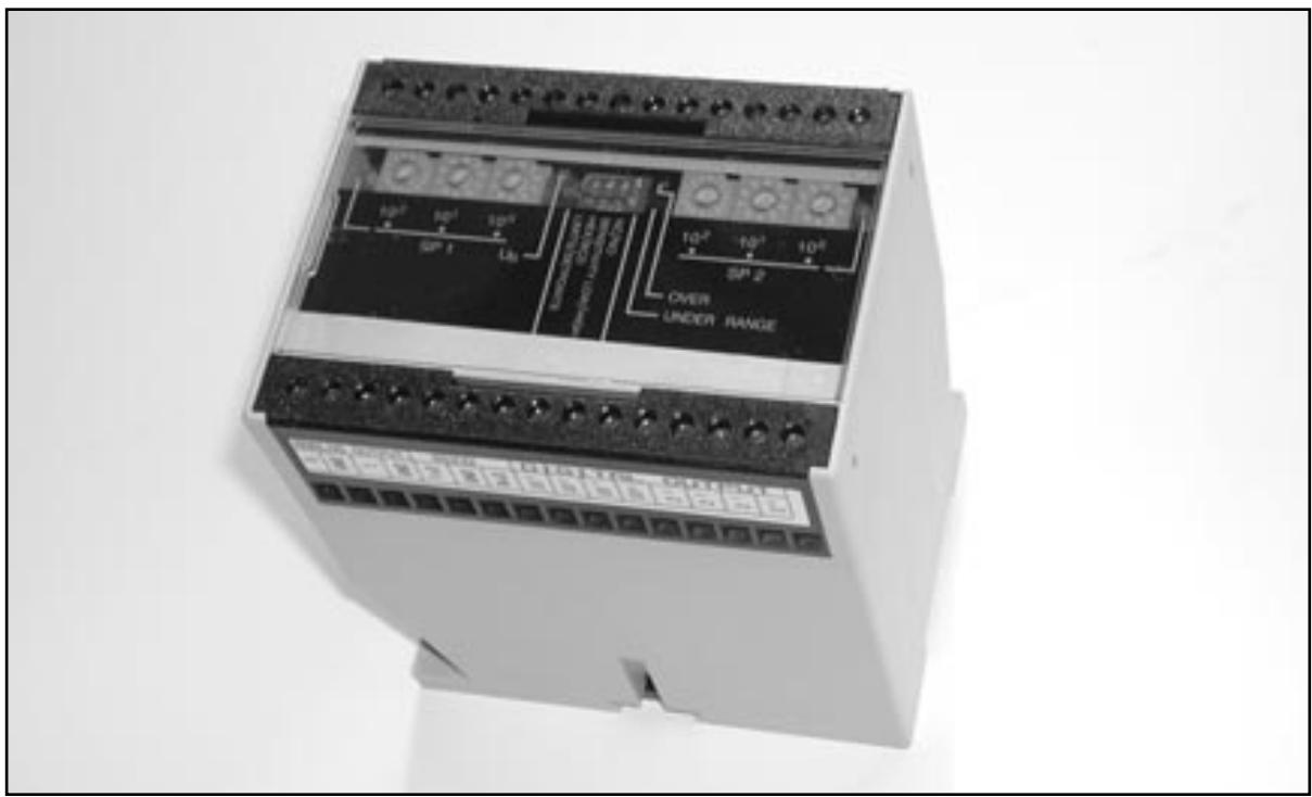
1. Mounting the unit
Mount the unit in a suitable place so the terminals and the switches are accessible. The unit is prepared for DIN-rail mounting.
2. Supplying the unit
Connect terminal 1 and 2 to +24 VDC and ground, respectively. Connect the sensor head UC80CND80FSM1 to the terminals 3, 4, 5, 6 and 8 according to the wiring diagram.
3. Programming the unit and the sensor head UC80CND80FSM1
Make the settings on the unit according to the following description.
Front Panel
This chapter gives a brief description of the switches and the LED's, which are all placed on the front panel.
Switches and LED's on the front panel
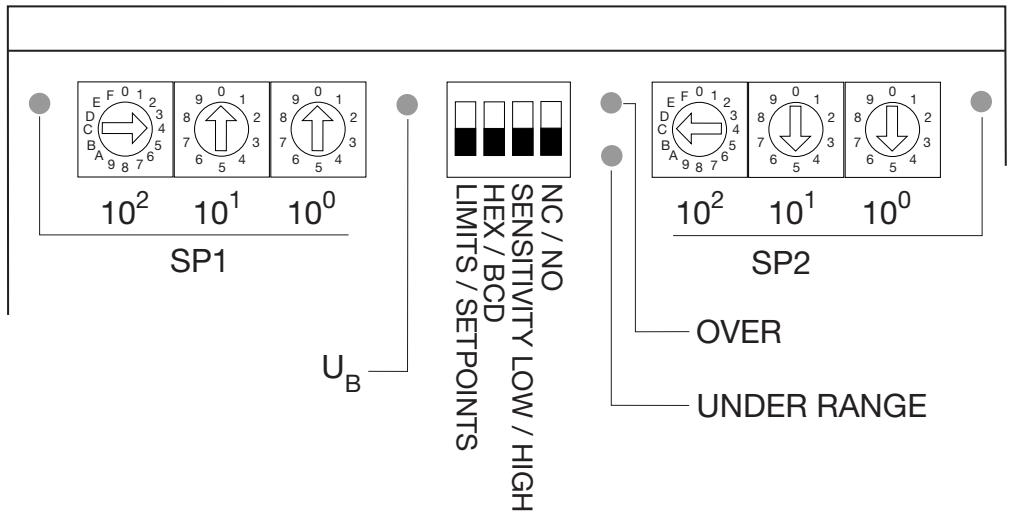
LED's
- SP1 ON when Setpoint 1 is active.
- SP2 ON when Setpoint 2 is active.
- U_B ON when power is applied.
- OVER ON when the measurement exceeds the programmed range.
- UNDER ON when the measurement is below the programmed range.
Digital switches
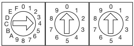
The two setpints can be adjusted individually with these 2 groups of 3 digital switches (1 hexadecimal and 2 decimal switches in each group). The resolution is in mm.
10^2 = hundreds switch
10¹ = tens switch
10° = units switch
Examples:
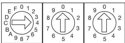
4, 0, 0, means a setting of 400 ~mm . With this setting of the switches to the left on the front plate, SP1 is set to 400 ~mm .
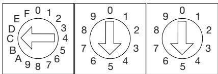
C, 5, 5, means a setting of 1255 ~mm (hex “C” = decimal “12”). With this setting of the switches to the right on the front plate, SP2 is set to 1255 ~mm .
The setting of the setpoints determines the polarity of the analogue output function. See "LIMITS" - function switch 1.
Function switches 1-4
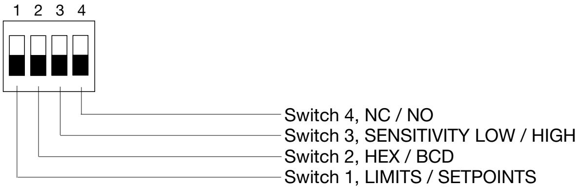
Switch 1: LIMITS / SETPOINTS
OFF: Output is in the range of 0....2000 mm (programmable). The analogue output signal is in the range of 150 to 2000 mm.
ON: Selectable polarity of the analogue output slope: Positive slope when SP1 < SP2 . SP1 defines the zero point (0 V or 4 mA) and the shortest distance. SP2 defines the final value (10 V or 20 mA) and the longest distance. Negative slope when SP2 < SP1 . SP1 defines the zero point (0 V or 4 mA) and the longest distance. SP2 defines the final value (10 V or 20 mA) and the shortest distance. See the following drawing.
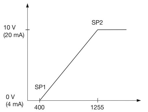
SP1 < SP2: Positive slope
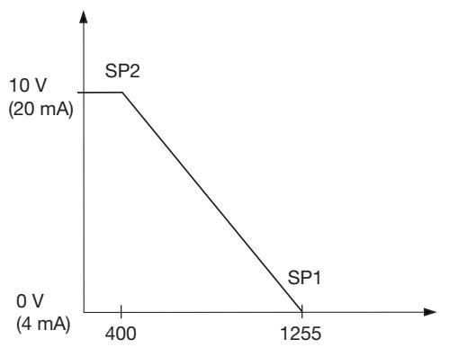
SP2 < SP1: Negative slope
Switch 2: HEX / BCD
OFF: Multiplexed data output, BCD coded.
ON: Multiplexed data output, HEX coded.
Switch 3: SENSITIVITY LOW / HIGH
OFF: Receive sensitivity and beam angle set to maximum.
ON: Receive sensitivity and beam angle set to minimum.
Switch 4: NC / NO
OFF: The switching outputs for setpoint 1 and setpoint 2 are normally open (NO).
ON: The switching outputs for setpoint 1 and setpoint 2 are normally closed (NC).
Serial Interface
Serial interface is fixed to data format: 9600, N, 8, 2. Special software is not needed. Communication is possible with every terminal program.
Hold / synchronizing input
By connecting Hold (HLD, active LO) to ground, the sensor is forced to stop operating and the last calculated distance is stored at the output. To avoid mutual interference from several sensors, these are simply
synchronized by interconnecting the HLD inputs. All synchronized sensors transmit at the same time.
Switching Outputs
The switching outputs are all PNP, 100mA and short-circuit protected.
SP1, SP2
Independently adjustable in steps of 1mm .
Switching hysteresis is fixed to approx. 1% .
Switching characteristic NO or NC can be selected.
ORA
If the analogue output has a positive slope, ORA indicates that no echo is received or the measured distance has exceeded the analogue range.
If the output slope is negative, ORA indicates that the distance is in the dead zone or below the analogue range.
URA
If the analogue output has a positive slope, URA indicates that the measured distance is in the dead zone or below the analogue range. If the output slope is negative, URA indicates that no echo is received or the distance has exceeded the analogue range.
Analogue Outputs
U Voltage output, 0 - 10V R_MIN = 1450 ohm
Current output, 4 - 20mA , R_MAX = 250 ohm
Multiplexed Digital Outputs
BCD or HEX. 4 data bits and 4 decade strobes NPN, open collector, 3+ V, 20mA , short-circuit protected.
Timing diagram of the multiplexed digital outputs - see following drawing.
Timing diagram of the multiplexed digital outputs
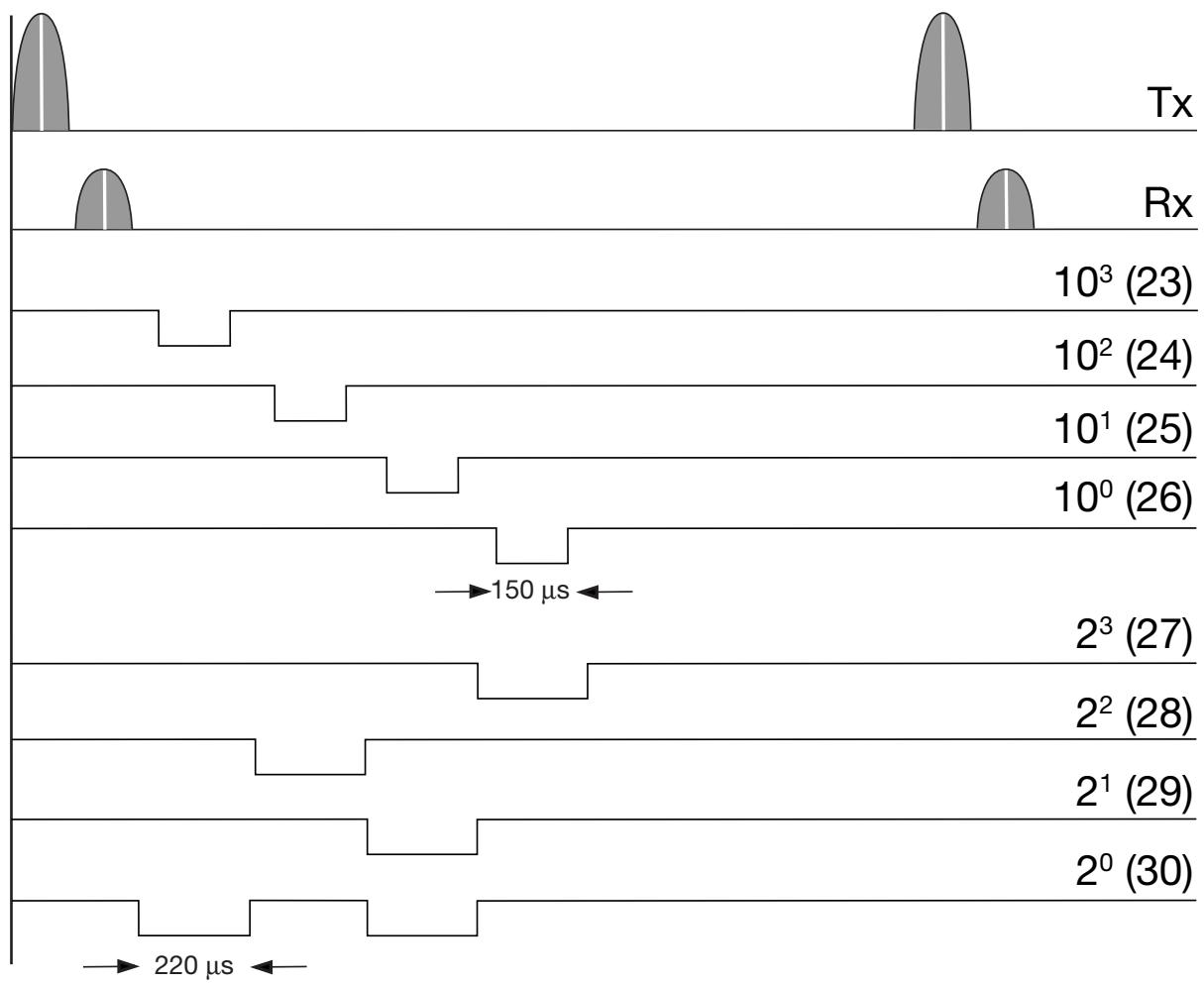
The actual output value is 1438.

SP1 < SP2: Pente positive
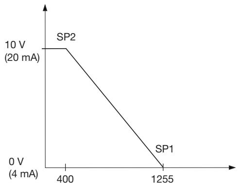
SP2 < SP1: Pente négative
To avoid interference from inductive voltage/ current peaks, separate the proximity switch power cables from any other power cables, e.g. motor, contactor or solenoid cables
Relief of cable strain
The cable should not be pulled
Protection of the sensing face
A proximity switch should not serve as mechanical stop
Switch mounted on mobile carrier
Any repetitive flexing of the cable should be avoided
Wiederholtes Biegendes Kabels vermeiden
| ordas de Instalación / Consiglio per l'Installazione / Installationsråd og -vink | |||
| FRANÇAIS | ESPÁNOL | ITALIANO | DANSK |
| Pour éviter les interférences issues des pics de tension et/ou des courants inductifs, veiller à toutes faire cheminer séparément les cables d'alimentation des détecteurs de proximité et les cables d'alimentation des moteurs, contacts ou solénoïdes | Para evitar interferrencias de tension inductiva/picos de intensidad se deben Separar los cables del sensor del resto de los cables de alimentación tales como cables de motor, contactores o solenoides | Al fine di evitare interferrenze di tipo elettrico, Separate i cavi di alimentazione del sensore di prossimità dai cavi di potenza | For at undgà stojindfly-delse fra induktive strom-/spændings-spidser skal aftaster-kablet adskilles fra andre kraftkabler, f.eks. fra motorer, transformater og magnet-ventiler |
| Tension des cables | Alivio de la tension del cable | Posizione del cavo | Aflastning af kabel |
| Éviter toute contrainte en traction du cable | No se debe tirar del cable | Il cavo non deve es-sere teso | Der bør ici trækkes i kablet |
| Protection de la face de détction du détector | Protección de la cara de détecisión | Protezione della parte sensible del sensore | Beskyttele af folerens tasteflade |
| Ne jamais utiliser un détector de proximité en tant que butée mécanique | Un sensor de proximidad nuncaDebe funciona como tope mecánico | I sensori di prossimità non devono essere usati per bloccaggi meccanici | En aftaster bør ici anvendes som mekanisk stop |
| Détector monté sur support mobile | Conector montado sobre portadora movable | Sensore installato su pedana mobile | Aftaster monteret på bevægeligt underlag |
| Eviter toute répétition de coubure dans le cheminement du cable | Evitar doclar el cable repetidas vezes | Evitare qualsiasi fles-sione ripetuta del cavo | Gentagne bojninger af kablet bør undgås |
CARLO GAVAZZI INDUSTRI A/S
CARLO GAVAZZI
Over Hadstenvej 40 DK-8370 Hadsten
Phone +45 89606100 Fax +45 86982522
Certified in accordance with ISO 9001
Gerätehersteller mit dem ISO 9001/EN 29 001 Zertifikat
Une société qualifiée selon ISO 9001
Empresa que cumple con ISO 9001
Certificato in conformità con l'ISO 9001
Kvalificeret i overensstemmelse med ISO 9001