
UA 30 CLD - Ultrasonic sensor CARLO GAVAZZI - Free user manual and instructions
Find the device manual for free UA 30 CLD CARLO GAVAZZI in PDF.
User questions about UA 30 CLD CARLO GAVAZZI
0 question about this device. Answer the ones you know or ask your own.
Ask a new question about this device
Download the instructions for your Ultrasonic sensor in PDF format for free! Find your manual UA 30 CLD - CARLO GAVAZZI and take your electronic device back in hand. On this page are published all the documents necessary for the use of your device. UA 30 CLD by CARLO GAVAZZI.
USER MANUAL UA 30 CLD CARLO GAVAZZI
Installation Hints 78
Installation
1. Mounting the sensor
Mount the sensor in the required position pointing at the target and make sure that the distance to the target is within the range of the sensor.
2. Supplying the sensor
To supply the sensor connect pin 2 to ground (0 V GND) and pin 1 to + (19 - 30 VDC).
3. Programming the sensor
Program the parametres according to the software description.
Software Description
The program UDSProg.EXE is designed for the Windows platform and makes it easy to set up the sensor by going through self-explaining menus.
Setting up COM Port and Address
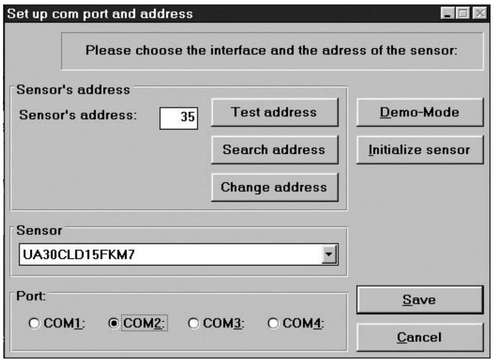
Port
The COM port used for the programming adapter is selected in the first window which appears when the program starts.
Sensor
In the drop-down menu, the correct sensor type is selected.
Address
The factory setting is 97. The address can be changed to any number between 0 and 99.
Search address
If a sensor has been connected and the address is unknown, "Search address" will find the correct address.
Demo-Mode
The sensor can run in demo-mode. Programming is not possible - only verification of the settings.
Initialize sensor
The sensor is reset to factory settings.
Ok
The settings are confirmed, and the main menu appears.
Main menu
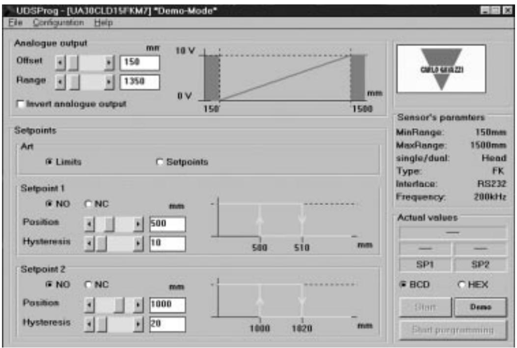
Analogue output
The analogue output is programmed with two parameters, offset and range. Offset is the distance from the sensor front to the closest end of the range. Range is the distance which causes the output to change from 0-10 V or 4-20 mA.
The offset and the range are selected in steps (in mm) - by scrolling the bars or by entering the values. Click the box if an inversion of the analogue output is required. The chosen output characteristic is shown.
Setpoint outputs
Setpoints are selected either as limits (using the mode "Limits") or as setpoints (using the mode "Setpoints") where a window is defined by "Position" and "Hysteresis".
Depending upon the choice of NO and NC, the setpoints are normally open or normally closed functions.
NO: When a setpoint is exceeded, the output impedance is high. Within the range, the output impedance is low and current flows (<100 mA).
NC: When a setpoint is exceeded, the output impedance is low and current flows (<100 mA). Within the range the output impedance is high.
Hysteresis
To ensure a stable output (when a measured distance equals the setpoint), a hysteresis can be programmed. Example for a NO output:
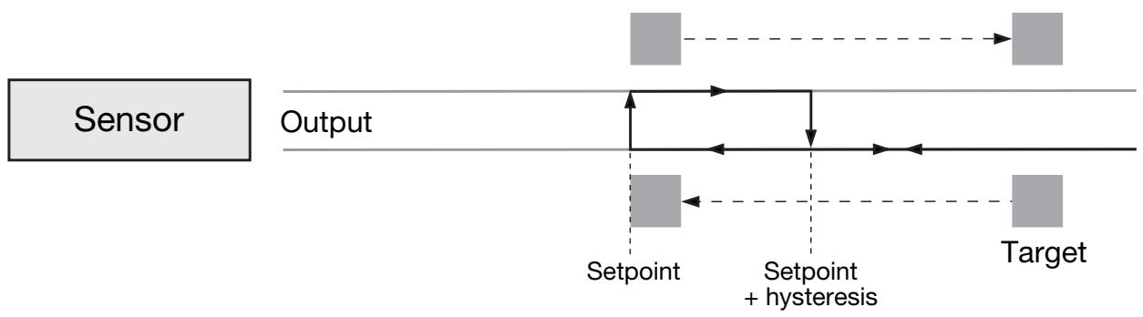
If a target approaches the sensor, the output will change when the distance equals the setpoint. If the target moves back from this point, the output changes back when the distance equals the setpoint + hysteresis.
File Menu
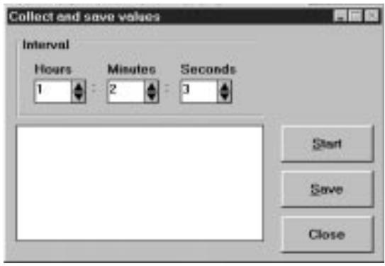
Collect and Save values
By choosing this, a new window opens. The frequency of the measurements can be selected (seconds, minutes and hours).
"Start" starts the recording.
"Save" stores the values (these can be evaluated in Excel).
Write sensor parametres
The parametres of the actual displayed settings are written in a file on disc.
Load sensor parametres
The parameters from a file on disc are loaded into the sensor.
Configuration Menu
Read configuration from sensor
The actual configuration will be downloaded from the sensor and shown.
Write configuration to sensor
The parametres shown on the screen will be transferred to the sensor. The same result is achieved by clicking the button "Start programming" in the main menu.
Initialize sensor
The sensor will be set to factory settings.
Configure sensor and interface
Sensor, COM-port and similar can be selected.
Advanced options
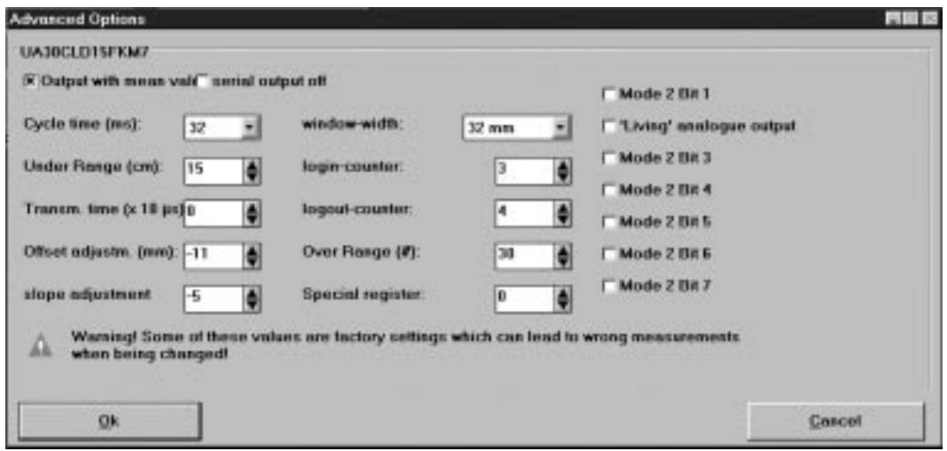
Output with mean value
Selection of a mean value procedure.
Serial output off
Disables serial output of data from the sensor. In case of time critical applications, this can be a useful function.
Cycle Time
Selection of cycle time in steps of 64, 32, 16, 8 or 4 ms.
The principle of distance measurement is shown in the following drawing.
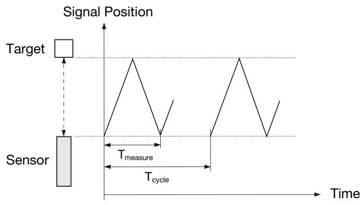
The diagram shows the signal position versus time. The sensor transmits an ultrasonic pulse. The target reflects the signal and the sensor receives this echo. The front of the sensor generates a new echo, an echo of the echo. This is a weak signal for no use - therefore the T_measure gates through only the usable signal (first echo). The T_cycle determines when the next pulse is transmitted.
The cycle time determines the response time of the sensor. Obviously, sensors used for long distance measurement also have long response times. With the programming of the cycle time, the response time of the sensor can be adjusted to the application.
The duration of the cycle time must be longer than the time needed to receive the echo of the transmitted pulse!
T_ measure is proportional to the distance to the object (from the pulse is transmitted and until the echo is received). T_ measure is a proportional expression for the distance; therefore the time is converted to a distance, expressed as an analogue value.
A guideline for maximum distance for a given cycle time is:
| Cycle time (ms) | Distance (m) |
| 4 | 0.3 |
| 8 | 0.7 |
| 16 | 2.5 |
| 32 | 4.5 |
| 64 | 10 |
Under Range
Under range can be adjusted in steps from 0 to 255~cm . During transmission the sensor cannot receive, and therefore the length of the transmission pulse determines the shortest detection distance. This range, limited by the length of the transmission pulse, is called the blind zone.
It is possible to control the under range. By setting the under range to a certain distance, it is possible to ignore echoes received from targets between the sensor front and the under range limit. This means that it is possible to ignore disturbing objects close to the sensor.
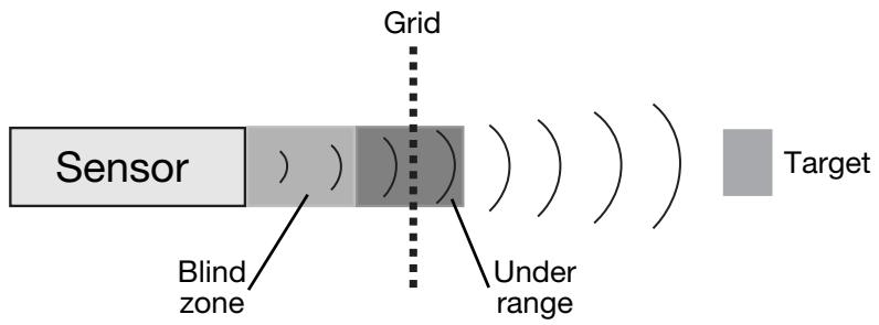
A sensor can detect targets for example through a protecting grid without being disturbed by the reflections from this grid.
Limitations
- Minimum under range is determined by the transducer ringing.
- Echoes of a massive target in the dead zone will be suppressed but 2nd or 3rd echoes can be received if the time is longer than the programmed dead zone. The output will indicate a distance which is 2 or 3 times longer.
Transmission Time
The transmission time defines the length of the pulse transmitted. It can be selected in 10 sec steps up to 2.55 ms. If 0 is selected, the length varies with the measured distance.
Offset and Slope Adjustment
These adjustments are done by factory. Please be careful and avoid change of these settings. These parameters are for fine-tuning.
Offset Adjustment
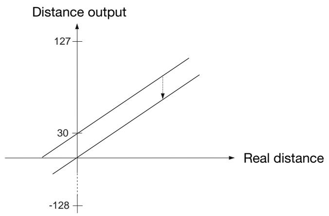
A difference can exist between the read-out and the real distance.
0 mm in the read-out and 0 mm in the physical length might differ. The position of 0 mm can be adjusted with the sensor head offset adjustment +/-128 mm in mm steps.
Example of negative offset (see following drawing):
The output indicates a distance which is 30 ~mm behind the target. By setting the offset to -30 ~mm , this misreading is neutralized as 30 ~mm are subtracted from all measurements.
Slope adjustment
The slope adjustment changes the slope of the analogue output. Using a wrong slope adjustment can affect the linearity and the temperature compensation.
Window Width
By operating the sensor with the mean value routine a window is created around the actual measured distance. All measured values within this window form the basis for the read-out. This read-out is then the centre of the window for the next read-out, and therefore the window is moving with the target. The maximum speed of the window movement limits the speed of a target that should be detected. If the target moves too fast, the fail pulse suppression algorithm will ignore distance measurements.
The maximum speed depends upon the cycle time and the size of the used measuring window. With the command "Cycle time adjustment" it is also possible to adjust the measurement window. Normal size of this measurement window is ± 32 mm.

The Login-Logout Counter is part of the 'Fail Pulse Suppression' software of the sensor. Please change only with caution!
Sensor electronics are well protected against electromagnetic disturbances from the environment. In addition, the microprocessor is used in a very effective way to filter the right signal out of a noisy environment. Factory settings are optimised to fulfill most of the measurement tasks.
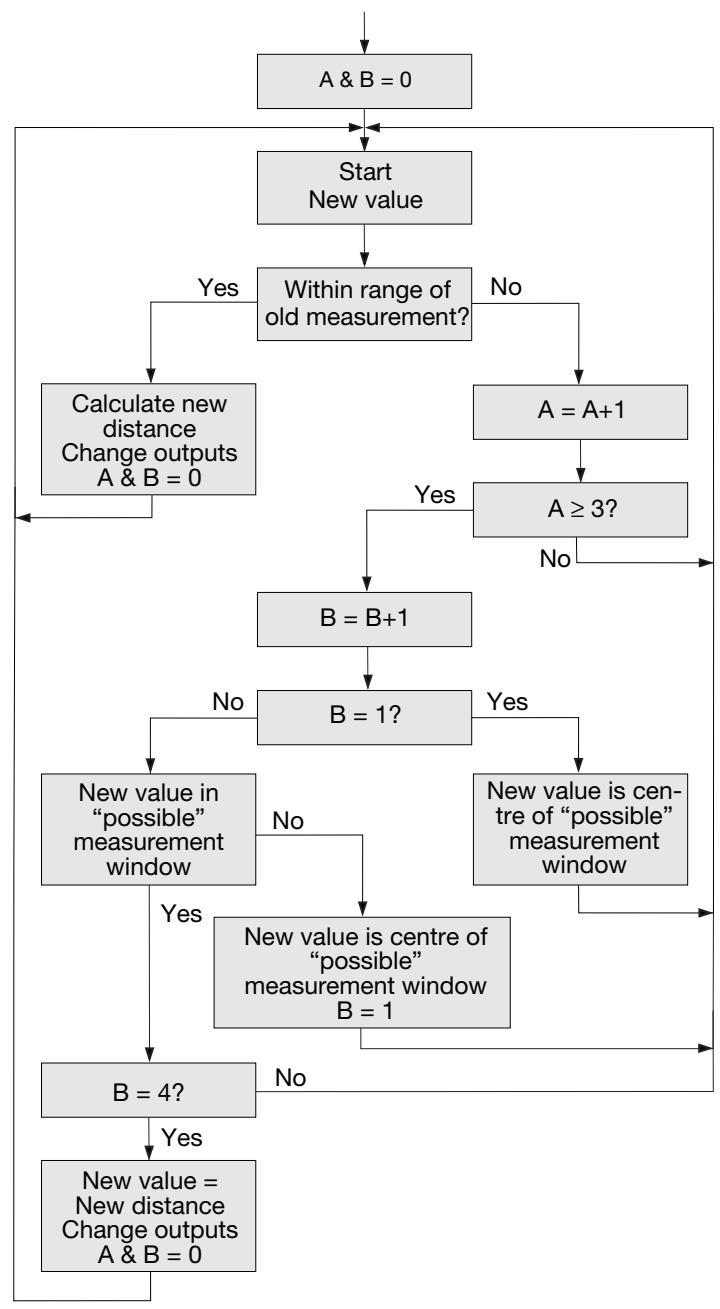
Selecting output with mean value activates the routine. With the actual measured distance as the centre, a ± 32 mm window is created. This window is called measurement window (for adjustment of this, see "Measurement Window").
If the next measurement or new value is within this measurement window, it will be used to calculate the new distance which then will be read-out. The new value is used as the centre of a new measurement window.
Two counters, 'A' for the read-out of the actual distance and 'B' for the login, are reset to 0. If the next measurement or new value is outside the window this measurement will be ignored and the distance output will remain unchanged. A counter counting the number of measurements outside the window is increased by 1.
If theLogout Counter A is below 3 (programmable), the program jumps back to the start and a new measurement is made.
If it is higher than or equals 3, the Login Counter B is increased.
If B = 1 , the measured value is assumed to be the new distance and a new measurement window is created. The program jumps back to the start and a new measurement starts.
If B > 1 and the new measurement is outside the new measurement window, B is set to 1 and the program jumps back to the start and a new measurement starts.
If B = 4 (programmable), the new measurement is realised as the new distance. Output is now changed and the logout and login counters are reset to 0. The program jumps back to the start and a new measurement is started.
The following flow chart shows the structure of the program.
Over Range
This counter can be set to 0-255. If the sensor has to measure the distance to a small target that is difficult to detect, the sensor outputs may be very unstable. They will flicker between the actual distance and over range. These unwanted changes can be suppressed with the over range counter.
The operation is shown in the flow chart:
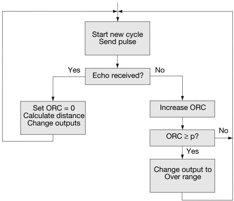
In the beginning of the measurement cycle, the sensor is transmitting a pulse.
If an echo is received, the over range counter ORC will be reset to 0, the new measured distance calculated and - if necessary - the outputs changed, and transmission of the next pulse will take place.
If no echo is received, the over range counter ORC will be increased.
If ORC is below the parameter p , there will be no changes in the output and the sensor will transmit a pulse during the next measurement cycle. If ORC is equal to or higher than p , the outputs will be changed to over range, and the sensor will transmit a pulse during the next measurement cycle.
Example: A sensor with the following setting:
Cycle time = 64 ms
Over Range = 200
If the target suddenly disappears, the sensor needs 200^*64 ~ms = 12.8 ~s until the outputs change to over range.
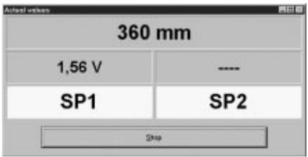
Additional window in test-mode
In the start modus, a separate window can be opened, where distance and status of switching output is displayed.
Adresse suchen (Search address)
Menu "Configuration"
Read configuration from sensor
Write configuration to sensor
Configure sensor and interface
Sensor's address (aftasterens adresse)
Offset Adjustment (forskydningsjustering)
≤ 100 ~mA (continuous)
Rated operating distance (S_n) / Nenn-Schaltabstand / Distance nominale de fonctionnement / Distancia nominal de detections / Distanza di attivazione nominale / Nominel tasteafstand
UA30CLD15 150 - 1500 mm
UA30CLD20 250 - 2000 mm
UA30CLD35 350 - 3500 mm
Output, analogue / Ausgang, analog / Sortie analogue / Salida analógica / Uscita, analogica / Udgang, analog
UA30CLD..FKM7: Analogue, 0-10 or 10-0 VDC / Analog, 0-10 oder 10-0 V DC / Analogue 0-10 ou 10-0 VCC / Analógica, 0 a 10 o 10 a 0 VCC / Analogica 0-10 o 10-0 VCC / Analog, 0-10 eller 10-0 V DC
UA30CLD..FGM7: Analogue, 4-20 or 20-4 mA / Analog, 4-20 oder 20-4 mA / Analogique 4-20 ou 20-4 mA / Analógica, 4 a 20 o 20 a 4 mA / Analogica 4-20 o 20-4 mA / Analog, 4-20 aller 20-4 mA
Scaling / Skalierung / Echelle / Cambio de escala / Scala / Skalering: Programmable / Programmierbar / Programmable / Programmable / Programmabile / Programmabile / Programmierbar
Linearity / Linearität / Linearité / Linearidad / Linearità / Linearitet: ± 0.5%/3 mm
Repeatability / Wiederholgenauigkeit / Repétivité / Repetibilitad / Ripetibilità / Gentagelsesnogagtighed: ± 0.2%/0.4 mm
ues / Especificaciones / Caratteristiche Tecniche / Specifikationer
Output, switching / Kontakausgang / Commutation des sorties / Salida, commutación / Uscita, commutazione / Udgang, aktivering
2 x PNP, open collector, NO/NC, 100 mA
2 x PNP, offener Kollektor, Schließer / Offner (NO/NC), 100 mA
2 x PNP, collecteur ouvert, NO/NC, 100 mA
2 x PNP, colector abierto, NA/NC, 100 mA
2 x transistor PNP, con collettore aperto, commutazione NA/NC, 100 mA
2 x transistor PNP, Åben kollektor, NO/NC, 100 mA
Operating frequency / Schaltfrequenz / Fréquence de marche / Frecuencia de funciona / Frequenza di attivazione / Driftsfrekvens
5 - 30 Hz, programmable / programmierbar / programmable / programmable / programmabile / programmbar
Protection / Schutz / Protection / Protección / Protezione / Beskyttelse
Reverse polarity, short-circuit, transients
1 24 VDC (24 VCC)
2 0V
3 Output, 0-10 V
Ausgang, 0-10 V / Sortie, 0-10 V / Salida, 0-10 V /
Uscita, 0-10 V /Udgang, 0-10 V
4 Switching output 1 (PNP)
Kontaktausgang 1 (PNP) / Commutation sortie 1 (PNP) /
Salida de conmutacion 1 (PNP) /
Uscita di commutazione 1 (PNP) / Aktiveringsudgang 1 (PNP) /
5 Switching output 2 (PNP)
Kontaktausgang 2 (PNP) / Commutation sortie 2 (PNP) /
Salida de conmutacion 2 (PNP) /
Uscita di commutazione 2 (PNP) / Aktiveringsudgang 2 (PNP) /
6 Hold
Halten / Attente / Retencion / Mantenere / Hold /
7 RS232 RxD..RS485-B
8 RS232 TxD..RS485-A
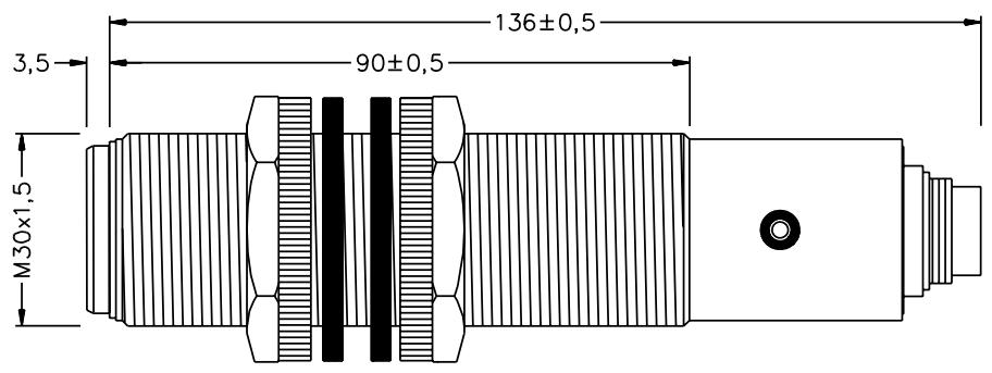
Dimensions / Abmessungen / Dimensions / Dimensiones /
Dimensioni / Dimensioner
Installation Hints / Installationshinweise / Consels d'Installation / No
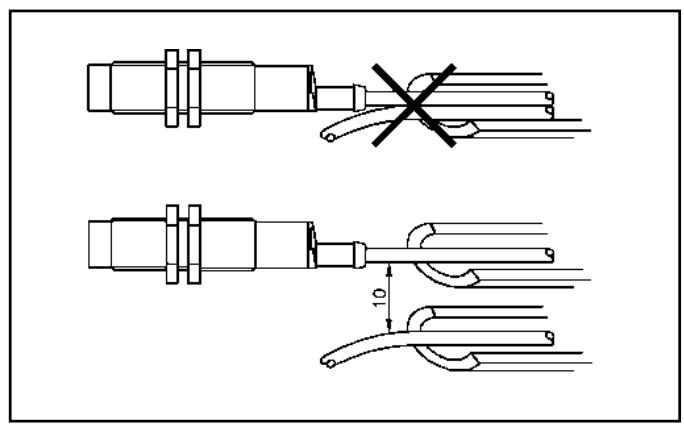
ENGLISH
To avoid interference from inductive voltage/ current peaks, separate the proximity switch power cables from any other power cables, e.g. motor, contactor or solenoid cables
DEUTSCH
Relief of cable strain
The cable should not be pulled
Protection of the sensing face
A proximity switch should not serve as mechanical stop
Switch mounted on mobile carrier
Any repetitive flexing of the cable should be avoided
Certified in accordance with ISO 9001