
OFFICECONNECT WL-524 - Wireless Access Point 3COM - Free user manual and instructions
Find the device manual for free OFFICECONNECT WL-524 3COM in PDF.
User questions about OFFICECONNECT WL-524 3COM
0 question about this device. Answer the ones you know or ask your own.
Ask a new question about this device
Download the instructions for your Wireless Access Point in PDF format for free! Find your manual OFFICECONNECT WL-524 - 3COM and take your electronic device back in hand. On this page are published all the documents necessary for the use of your device. OFFICECONNECT WL-524 by 3COM.
USER MANUAL OFFICECONNECT WL-524 3COM
3Com OfficeConnect® Wireless 54 Mbps 11g Access Point
3CRWE454G75 / WL-524
The 3Com OfficeConnect® Wireless 54 Mbps 11g Access Point is IEEE 802.11g compatible, IEEE 802.11b interoperable, and supports both 11b and 11g clients simultaneously. Additionally, this 3Com OfficeConnect Wireless Access Point offers highly-secure wireless connectivity to your wired network with IEEE 802.1x WEP and WPA/WPA2 data encryption and MAC-address filtering.
This Quick Start Guide describes the basic steps necessary to install and configure your 3Com OfficeConnect Wireless Access Point (3CRWE454G75 / WL-524). Throughout this guide the OfficeConnect Wireless 54 Mbps 11g Access Point is simply referred to as the Access Point.
About This Guide
This guide describes the basic installation of the Access Point. It covers the following topics:
- 3Com OfficeConnect 54 Mbps 11g Access Point Features
- Observing Safety Precautions
- Step 1: Unpacking the Access Point
- Step 2: Preparing for Installation
- Step 3: Attaching the Antenna
- Step 4: Mounting the Access Point
- Step 5: Checking the LED Indicators
- Step 6: Configuring the Access Point
- Troubleshooting
OfficeConnect 54 Mbps 11g Access Point Features
| Feature | Description |
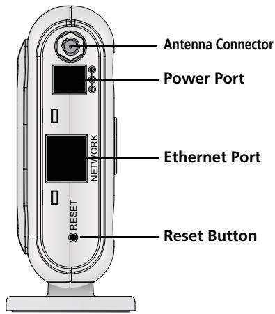
| Power Port | The power port connects to the external power supply. Use only the 3Com external power supply included in this package to power the Access Point. |
| Ethernet Port | The Ethernet port provides a 10/100BASE-TX Ethernet connection to a 3Com Wireless LAN switch. Use a suitable RJ45 cable to connect your Access Point to a computer or other equipment that has an Ethernet port (such as a hub or a switch). This port has an automatic MDI/MDIX feature, which allows you to use either a straight-through or a crossover cable. |
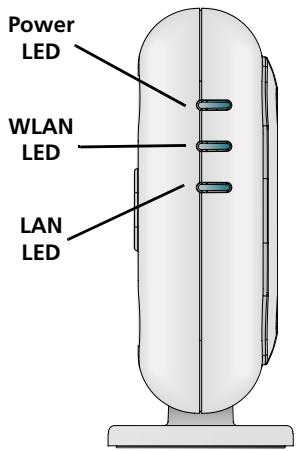
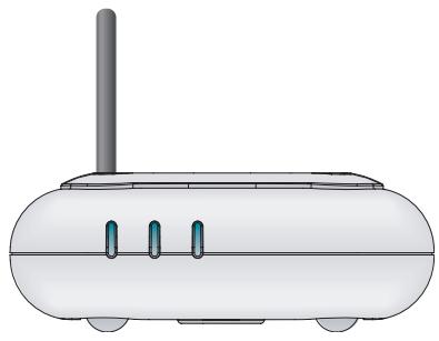
| LEDs | The LEDs indicate power and network activity. See “Checking the LED Indicators” on page 5 for details. |
| Antenna Connector | One RSMA antenna connector allows you to connect an antenna that operates in the 2.4 GHz band. |
| Reset Button | Push the reset button to restart the Access Point. To return the unit to factory defaults, power off the unit, press and hold the Reset button, and power on the unit again. Continue holding the Reset button for 15 seconds and release. Cycle power again and AP will have the factory defaults. |
Observing Safety Precautions
This equipment must be installed in compliance with local and national building codes, regulatory restrictions, and FCC rules. For the safety of people and equipment, only professional network personnel should install the Access Point.

WARNING: To comply with FCC radio frequency (RF) exposure limits, a minimum body-to-antenna distance of 20cm (8 in.) must be maintained when the Access Point is operational.

WARNING: To avoid possible injury or damage to equipment, you must use power supply equipment that is safety certified according to UL, CSA, IEC, or other applicable national or international safety requirements for the country of use. All references to power supply in this document refer to equipment meeting these requirements.
1. Unpacking the Access Point
Make sure that you have the following items, which are included with the Access Point:
- One OfficeConnect Wireless 54 Mbps 11g Access Point
- One 3Com power adapter for use with the Access Point
- One cradle for vertical tabletop mounting
- Wall-mounting hardware: includes two threaded screws
- One CD-ROM containing the Setup Wizard software and an additional copy of this Quick Start Guide
- One Warranty Flyer
2. Preparing for Installation
It is advisable to connect the power and check the Ethernet cables and LEDs before installing the Access Point in a hard-to-reach location. Additionally, observe the following items before mounting or connecting the Access Point:
| Installation Item | Description |
| Hub or Switch | To connect your wireless network to your wired network you will need an additional hub or switch connected to the Access Point's Ethernet port. |
| Cabling | Make sure that standard Ethernet cable is installed at the site before you install the Access Point. |
| Power Requirements | Power can only be supplied using 3Com Power Adaptor which is included with the Access Point. Make sure the power outlet is accessible. The power supply plug is the only means of disconnecting the Access Point from power. |
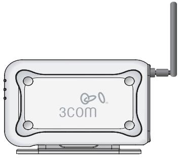
| MAC Address | Record the Access Point MAC address in a safe place before the Access Point is installed in a hard-to-reach location. The MAC address is printed on the back of the Access Point. |
3. Attaching the Antenna
Carefully unpack the standard detachable antenna that came included with your Access Point. Screw the antenna on to the antenna connector on the Access Point and hand-tighten it. After network startup, you may need to adjust the antenna to fine-tune coverage in your area.
For best results, adjust the antenna so that it is perpendicular to the floor and ceiling.

CAUTION: Do not handle the antenna tips, especially after they are connected to the Access Point. This could lead to electrostatic discharge (ESD), which could damage the equipment.
4. Mounting the Access Point
Tabletop Mount (horizontal)
Tabletop Mount (vertical)

CAUTION: The Access Point is intended for indoor use only. Do not install the Access Point outdoors unless you install it in an appropriate outdoor enclosure.
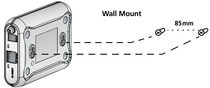
Wall Mounting
To mount the Access Point to a wall:
1 Locate a position on the wall which is free of obstructions.
2 Screw two mounting screws into the wall 85mm apart.
3 Connect the Ethernet cable and power cable to the ports on the side of the Access Point.
4 Align the holes on the back of the Access Point with the screws and hang the Access Point on the screws.
Tabletop Mounting
To install the Access Point on a flat surface such as a table or desktop:

CAUTION: Do not place the Access Point on any type of metal surface. Select a location that is clear of obstructions and provides good reception.
1 If you want to mount the Access Point vertically, secure the cradle to the bottom of the Access Point. If you want to mount the Access Point horizontally, simply leave off the cradle.
2 Place the Access Point on the table or other flat surface.
3 Connect the Ethernet cable and power cable to the ports on the side of the Access Point.
5. Checking the LED Indicators
When the Access Point is connected to power, LEDs indicate activity as described in the following table. A steady lit LED indicates connection; a blinking LED indicates activity.
| LED | Color | Indicates | |
| Power | Green | The Access Point is powered up and operating normally. | |
| Off | The Access Point is not receiving power or there is a fault with the power supply. | ||
| WLAN | Green | If the LED is on it indicates that wireless networking is enabled. If the LED is flashing, the link is OK and data is being transmitted or received. | |
| Off | No wireless link is present. | ||
| LAN | Green | If the LED is on, the Ethernet link between the port and the next piece of network equipment is OK. If the LED is flashing, the link is OK and data is being transmitted or received. | |
| Off | No Ethernet link is present. |
6. Configuring the Access Point
The CD shipped with your Access Point includes software to help you set up and administer the Access Point. Perform the following steps to configure your Access Point for the first time:
1 Insert the 3Com Access Point CD into your PC's CD-ROM drive. Your PC must be on your wired network to set up the Access Point.
2 When the OfficeConnect Installation screen appears, click Run Discovery Application.
If the Installation screen does not appear automatically, launch the program by typing d:\setup.exe (where "d" is the drive letter for your PC's CD-ROM drive).
3 Follow the Setup Wizard's instructions on the screen.
4 (Optional) Change the default settings.
The Access Point is preconfigured with common default parameters. If you want to change these settings, use your Web browser to configure the Access Point using its Web-based interface.
The default wireless settings for the Access Point are:
| Password: | admin |
| SSID: | 3Com |
| Channel: | 11-2.462GHz |
7. Troubleshooting
What to do if the Setup Wizard does not detect your Access Point
Be sure the Access Point has finished booting
If you run the Setup Wizard before the Access Point has fully booted, the application may not be able to find the device. During its boot-up sequence, the Access Point tries to get an IP address from a DHCP server on the network. After 2 to 3 minutes of trying unsuccessfully, the Access Point sets itself to use the factory default static IP address of 192.168.1.250, subnet mask
255.255.255.0. Sometimes the default IP address will appear in the Setup Wizard just before the proper DHCP-assigned address is set. If opening the web browser to manage the Access Point is initially unsuccessful, try running the wizard again to get the proper address.
Be sure the Access Point and your PC are on the same network
The Access Point and the PC must be on the same wired network and subnetwork for the Setup Wizard to be able to detect the Access Point.
Connect to the Access Point manually
During boot up, if the Access Point does not detect a DHCP server after 2 or 3 three minutes, it will assign itself the factory default static IP address of 192.168.1.250, subnet mask 255.255.255.0. To communicate with the Access Point using the default address, follow this procedure:
1 Set the IP address of your PC to any address in the same IP subnet as the Access Point (for example 192.168.1.10), with subnet mask the same as the Access Point (255.255.255.0).
2 Point your web browser at the Access Point default address: 192.168.1.250.
3 At this time you will be able to log in and change the operating mode, and change the static IP address if needed.
3Com recommends that you set a static IP address in the Access Point so that you will always know the IP address. Depending on the DHCP server used, a different IP address could be assigned to the Access Point with each reboot.
Reset the Access Point to Factory Defaults
To return the Access Point to the factory defaults power off the unit, press and hold the Reset button, and power on the unit again. Continue holding the Reset button for 15 seconds and release. Cycle power again and the Access Point will have the factory default conditions.
Note that the default IP address will only become available after the Access Point spends 2 to 3 minutes searching for an address from a DHCP server.
For additional information about your Access Point please visit 3Com's World Wide Web site: www.3Com.com.
3Com OfficeConnect® Wireless 54 Mbps 11g Access Point 3CRWE454G75 / WL-524
| Password: | admin |
| SSID: | 3Com |
| Kanal: | 11-2.462GHz |
7. Fehlersuche
The 3Com OfficeConnect Wireless 54 Mbps 11g Access Point (WL-524) must be installed and used in strict accordance with the manufacturer's instructions as described in the user documentation that comes with the product.

This product contains encryption. It is unlawful to export out of the U.S. without obtaining a U.S. Export License.
This product does not contain any user serviceable components. Any unauthorized product changes or modifications will invalidate 3Com's warranty and all applicable regulatory certifications and approvals.
This product can only be used with the supplied antenna(s). The use of external amplifiers or non-3Com antennas may invalidate regulatory certifications and approvals.
CAUTION: EXPOSURE TO RADIO FREQUENCY RADIATION
This device generates and radiates radio-frequency energy. In order to comply with FCC radio-frequency exposure guidelines for an uncontrolled environment, this equipment must be installed and operated while maintaining a minimum body to antenna distance of 20~cm (approximately 8 in.).
The installer of this radio equipment must ensure that the antenna is located or pointed such that it does not emit RF field in excess of Health Canada limits for the general population; consult Safety Code 6, obtainable from Health Canada's website www.hc-sc.gc.ca/rpb.
This product must maintain a minimum body to antenna distance of 20~cm . Under these conditions this product will meet the Basic Restriction limits of 1999/519/EC [Council Recommendation of 12 July 1999 on the limitation of exposure of the general public to electromagnetic fields (0 Hz to 300 GHz)].
US — RADIO FREQUENCY REQUIREMENTS
This device must not be co-located or operated in conjunction with any other antenna or transmitter.
USA—FEDERAL COMMUNICATIONS COMMISSION (FCC)
This device complies with part 15 of the FCC Rules. Operation is subject to the following two conditions: (1) This device may not cause harmful interference, and (2) this device must accept any interference received, including interference that may cause undesired operation.
This equipment has been tested and found to comply with the limits for a Class B digital device, pursuant to Part 15 of FCC Rules. These limits are designed to provide reasonable protection against harmful interference in a residential installation. This equipment generates, uses, and can radiate radio frequency energy. If not installed and used in accordance with the instructions, it may cause harmful interference to radio communications. However, there is no guarantee that interference will not occur in a particular installation. If this equipment does cause harmful interference to radio or television reception, which can be determined by tuning the equipment off and on, the user is encouraged to try and correct the interference by one or more of the following measures:
Reorient or relocate the receiving antenna
- Increase the distance between the equipment and the receiver
- Connect the equipment to outlet on a circuit different from that to which the receiver is connected
- Consult the dealer or an experienced radio/TV technician for help
The user may find the following booklet prepared by the Federal Communications Commission helpful: The Interference Handbook
This booklet is available from the U.S. Government Printing Office, Washington, D.C. 20402. Stock No. 004-000-0034504.
3Com is not responsible for any radio or television interference caused by unauthorized modification of the devices included with this 3Com OfficeConnect Wireless 54 Mbps 11g Access Point (WL-524), or the substitution or attachment of connecting cables and equipment other than specified by 3Com.
The correction of interference caused by such unauthorized modification, substitution or attachment will be the responsibility of the user.
Changes or modifications not expressly approved by 3Com could void the user's authority to operate this equipment.
MANUFACTURER'S DECLARATION OF CONFORMITY
3Com Corporation
350 Campus Drive
Marlborough, MA 01752-3064, USA
(800)527-8677
Date: 24 March 2006
DeclarethattheProduct:
Brand Name: 3Com Corporation
Model Number: WL-524
Equipment Type: 3Com OfficeConnect Wireless 54 Mbps 11g Access Point
Complies with Part 15 of the FCC rules. Operation is subject to the following two conditions: (1) this device may not cause harmful interference, and (2) this device must accept any interference received, including interference that may cause undesired operation.

3Com OfficeConnect Wireless 54 Mbps 11g Access Point Model WL-524
CANADA-INDUSTRY CANADA (IC)
This device complies with RSS 210 of Industry Canada.
Operation is subject to the following two conditions: (1) this device may not cause interference, and (2) this device must accept any interference, including interference that may cause undesired operation of this device."
The term "IC" before the equipment certification number only signifies that the Industry Canada technical specifications were met.
To reduce potential radio interference to other users, the antenna type and its gain should be so chosen that the equivalent isotropically radiated power (EIRP) is not more than that required for successful communication. To prevent radio interference to the licensed service, this device is intended to be operated indoors and away from windows to provide maximum shielding. Equipment (or its transmit antenna) that is installed outdoors is subject to licensing.
This Class B digital apparatus complies with Canadian ICES-003.
AVIS DE CONFORMITE A LA REGLEMENTATION D'INDUSTRIE CANADA
This device has been tested and certified according to the following safety standards and is intended for use only in Information Technology Equipment which has been tested to these or other equivalent standards:
- UL Standard 60950-1
CAN/CSA C22.2 No. 60950-1
IEC 60950-1
EN 60950-1
Usage restrictions apply. See documentation
| This equipment may be operated in | |||||||
| AT | BE | CY | CZ | DK | EE | FI | FR |
| DE | GR | HU | IE | IT | LV | LT | LU |
| MT | NL | PL | PT | SK | SI | ES | SE |
| GB | IS | LI | NO | CH | BG | RO | TR |
Intended use: IEEE 802.11g/b radio LAN device
NOTE: To ensure product operation is in compliance with local regulations, select the country in which the product is installed. Refer to 3Com OfficeConnect Wireless 54 Mbps 11g Access Point (WL-524) User Guide.
EUROPE — DECLARATION OF CONFORMITY IN LANGUAGES OF THE EUROPEAN COMMUNITY
| Česky [Czech] | 3Com Corporation tímtó prohlášuje, ze tento RLAN device je ve shodě se základnímí požadavyk a dalími příslušnými ustanoveními směrnice 1999/5/ES. |
| Dansk [Danish] | Undertegnede 3Com Corporation erkrärer herved, at følgende udstyr RLAN device overholder de væsentlige krav og øvrige relevante krav i direktiv 1999/5/EF. |
| Deutsch [German] | Hiermit erklart 3Com Corporation, dass sich das Gerät RLAN device in Übereinstimmung mit den grundlegenden Anforderungen und den übrigen einschläg-gen Bestimmungen der Richtlinie 1999/5/EG befindet. |
| Eesti [Estonian] | Käesolevaga kinnitab 3Com Corporation seadme RLAN device vastavust direktivi 1999/5/EU pöhinóuetele ja nimetatud direktivist tulenevatele teistele asjakohastele sâtetele. |
| English | Hereby, 3Com Corporation, declares that this RLAN device is in compliance with the essential requirements and other relevant provisions of Directive 1999/5/EC. |
| Espanol [Spanish] | Por medio de la presente 3Com Corporation declara que el RLAN device cumple con los requisitos esencias y caulesquiera或其他 dispositions aplicables o exigibles de la Directiva 1999/5/CE. |
| Eλληνική [Greek] | ME THN ΠΑΝΟΥΣΑ 3Com Corporation ΔΗλΩNEI OTI RLAN device ΣΥΜΜΟΦΩΝΕΤΑΙ ΠΡΟΣ TΙΣ ΟΥΣΙΟΔΕΙΣ ΑΝΑΙΤΗΣΕΙΣ KΑΙ TΙΣ ΑΟΙΝΕΣ ΣχETAΚΕ ΣΙΑΤΑΕΙΣ ΘΗ ΕΟΗΓΑΙΣ 1999/5/EK. |
| François [French] | Par laprésente 3Com Corporation déclare que l'appareil RLAN device est conforme aux exigences essentielles et aux autres dispositions pertinentes de la directive 1999/5/CE. |
| Italiano [Italian] | Con la presente 3Com Corporation dichiarare che questo RLAN device è conforme ai requisiti essenziali ed alle autres disposizioni pertinenti stabilite alla direttiva 1999/5/CE. |
| Latviski [Latvian] | Ar šo 3Com Corporation deklarē, ka RLAN device atbilst Direktīvas 1999/5/EEKūtiskajām prasībām un citiem ar to saisǐflaṭijem noteikumiem. |
| Lietuviç [Lithuanian] | Šiuo 3Com Corporation deklarujoa, kad šs RLAN device atitinka esminius reikalavimus ir kitas 1999/5/EB Direktyvos nuostatas. |
| Nederlands [Dutch] | Hierbij verklaart 3Com Corporation dat het toestel RLAN device in overeen-stemming is met de essentièle eisen en de andere relevante bepalingen van richtlijn 1999/5/EG. |
| Malti [Maltese] | Hawnhekk, 3Com Corporation, jiddikjara li dan RLAN device jikkonforma malhtigijiet essenzjali u ma provvedimenti ohrajn relevanti li hemm fid-Dirrettiva 1999/5/EC. |
| Magyar [Hungarian] | Alulírott, 3Com Corporation nyilatkozom, hogy a LAN device megfelel a vonatkozó alapvető követelményeknek és az 1999/5/EC irányelv égyeb előrá-sainak. |
| Polski [Polish] | Niniejszym 3Com Corporation oswiadcza, ze LAN device jest zgodny z zaśdniczymi wymogami oraz pozostalymi stosownymi postanowieniami Dyrektywy 1999/5/EC. |
| Portuguès [Portuguese] | 3Com Corporation declara que este LAN device está conforme com os requisitos essenciais e autres disposções da Directa 1999/5/CE. |
| Slovensko [Slovenian] | 3Com Corporation izjavla, da je ta LAN device v skladu z bistvenimi zaht-vami in ostalimi relevantnimi določili directiveste 1999/5/ES. |
| Slovensky [Slovak] | 3Com Corporation týmto vyhlasje, ze LAN device spína základné požiadavyk a větky príslušné ustanovenia Smernice 1999/5/ES. |
| Suomi [Finnish] | 3Com Corporation vakuuttaa täten etta LAN device typpinen laite on direkti-ivin 1999/5/EY oleellisten vaatimusten ja sită koskevien direktiivin muiden ehtojen mukainen. |
| Svenska [Swedish] | Härmed intygår 3Com Corporation attenna LAN device står I överensstäm-melse med de väsentliga egenskapskrav och övriga relevanta bestämmelser som framgår av direktiv 1999/5/EG. |
| Ślenska [Icelandic] | Hér með lysir 3Com Corporation yfir Þvi að LAN device erí samræmi við grunnkröfur og aðrkröfur, sem geröar eru i tilskipun 1999/5/EC. |
| Norsk [Norwegian] | 3Com Corporation erklærer herved at utstyret LAN device er i samsvar med de grunnleggende krav og övrige relevante krav i direktiv 1999/5/EF. |
A copy of the signed Declaration of Conformity can be downloaded from the Product Support web page for the 3CRWE454G75 (WL-524) at http://www.3com.com.
Also available at http://support.3com.com/doc/WL-524_EU_DOC.pdf
EUROPE - RESTRICTIONS FOR USE OF 2.4GHz FREQUENCIES IN EUROPEAN COMMUNITY COUNTRIES
- This device may be operated indoors or outdoors in all countries of the European Community using the 2.4GHz band: Channels 1 - 13, except where noted below.
- In Italy the end-user must apply for a license from the national spectrum authority to operate this device outdoors.
- In Belgium outdoor operation is only permitted using the 2.46 - 2.4835 GHz band: Channel 13.
- In France outdoor operation is only permitted using the 2.4 - 2.454 GHz band: Channels 1 - 7.