
Wireless 11n - Router 3COM - Free user manual and instructions
Find the device manual for free Wireless 11n 3COM in PDF.


| Product Type | Wireless 11n ADSL Firewall Router (3CRWDR300A-73 / 3CRWDR300B-73) |
| Dimensions (approximate) | 150 x 100 x 30 mm (5.9 x 3.9 x 1.2 in) |
| Weight (approximate) | 200 g (7 oz) |
| Power Supply | 15V DC, 0.8A (Class 2 / LPS adapter included) |
| Interfaces | 1x ADSL (RJ-11 or RJ-45), 4x 10/100 Ethernet LAN ports |
| Wireless Standard | 802.11n draft 2.0, backward compatible with 802.11b/g |
| Wireless Security | WEP 64/128-bit, WPA-PSK, WPA2-PSK, WPA with RADIUS |
| Firewall Features | SPI firewall, NAT, URL filtering, MAC/IP filtering, DMZ |
| VPN Support | IPSec, PPTP, L2TP passthrough |
| WAN Connection Types | PPPoE, PPPoA, Bridge Mode, Routing Mode over ATM, Dynamic/Fixed IP |
| LED Indicators | Power (white), Alert (amber), ADSL Sync (blue), ADSL Data (blue), WLAN (blue), LAN (4x blue), WPS (blue) |
| Buttons | WiFi On/Off, WPS, Reset |
| Antenna | 2 external antennas (diversity) |
| Software Features | DHCP server, QoS, WMM, WDS, SNMP, Syslog, DDNS |
| Mounting | Desktop or wall mount (screws and anchors not included) |
| Operating Temperature | 0°C to 40°C (32°F to 104°F) |
| Humidity | 10% to 90% non-condensing |
| Maintenance & Cleaning | No user-serviceable parts. Clean with a dry, soft cloth. |
| Safety Compliance | UL 60950-1, CAN/CSA C22.2 No. 60950-1, IEC/EN 60950-1, FCC Part 15, CE |
| Package Contents | Router, power adapter, telephone cable (Annex A) or Ethernet cables (Annex B), rubber feet, CD-ROM, installation guide, support sheet, warranty sheet |
Frequently Asked Questions - Wireless 11n 3COM
User questions about Wireless 11n 3COM
0 question about this device. Answer the ones you know or ask your own.
Ask a new question about this device
Download the instructions for your Router in PDF format for free! Find your manual Wireless 11n - 3COM and take your electronic device back in hand. On this page are published all the documents necessary for the use of your device. Wireless 11n by 3COM.
USER MANUAL Wireless 11n 3COM
Wireless 11n ADSL Firewall Router User Guide
WL-603
3CRWDR300A-73 3CRWDR300B-73
http://www.3Com.com/
Part No. 10016794 Rev AA
Published July 2008

natural_image
Abstract black ink brushstroke design on white background, no text or symbols present3Com Corporation 350 Campus Drive, Marlborough, MA USA 01752-3064
Copyright © 2004, 2005, 2006, 2007, 2008, 3Com Corporation. All rights reserved. No part of this documentation may be reproduced in any form or by any means or used to make any derivative work (such as translation, transformation, or adaptation) without written permission from 3Com Corporation.
3Com Corporation reserves the right to revise this documentation and to make changes in content from time to time without obligation on the part of 3Com Corporation to provide notification of such revision or change.
3Com Corporation provides this documentation without warranty, term, or condition of any kind, either implied or expressed, including, but not limited to, the implied warranties, terms or conditions of merchantability, satisfactory quality, and fitness for a particular purpose. 3Com may make improvements or changes in the product(s) and/or the program(s) described in this documentation at any time.
If there is any software on removable media described in this documentation, it is furnished under a license agreement included with the product as a separate document, in the hard copy documentation, or on the removable media in a directory file named LICENSE.TXT or !LICENSE.TXT. If you are unable to locate a copy, please contact 3Com and a copy will be provided to you.
UNITED STATES GOVERNMENT LEGEND
If you are a United States government agency, then this documentation and the software described herein are provided to you subject to the following:
All technical data and computer software are commercial in nature and developed solely at private expense. Software is delivered as "Commercial Computer Software" as defined in DFARS 252.227-7014 (June 1995) or as a "commercial item" as defined in FAR 2.101(a) and as such is provided with only such rights as are provided in 3Com's standard commercial license for the Software. Technical data is provided with limited rights only as provided in DFAR 252.227-7015 (Nov 1995) or FAR 52.227-14 (June 1987), whichever is applicable. You agree not to remove or deface any portion of any legend provided on any licensed program or documentation contained in, or delivered to you in conjunction with, this User Guide.
Unless otherwise indicated, 3Com registered trademarks are registered in the United States and may or may not be registered in other countries.
3Com, and the 3Com logo are registered trademarks of 3Com Corporation.
Intel and Pentium are registered trademarks of Intel Corporation. Microsoft, MS-DOS, Windows, and Windows NT are registered trademarks of Microsoft Corporation. Novell and NetWare are registered trademarks of Novell, Inc. UNIX is a registered trademark in the United States and other countries, licensed exclusively through X/Open Company, Ltd.
Netscape Navigator is a registered trademark of Netscape Communications.
JavaScript is a trademark of Sun Microsystems
Wi-Fi and the Wi-Fi logo are registered trademarks of the WI-Fi Alliance.
IEEE and 802 are trademarks of the Institute of Electrical and Electronics Engineers, Inc.
All other company and product names may be trademarks of the respective companies with which they are associated.
ENVIRONMENTAL STATEMENT
It is the policy of 3Com Corporation to be environmentally-friendly in all operations. To uphold our policy, we are committed to:
Establishing environmental performance standards that comply with national legislation and regulations.
Conserving energy, materials and natural resources in all operations.
Reducing the waste generated by all operations. Ensuring that all waste conforms to recognized environmental standards. Maximizing the recyclable and reusable content of all products.
Ensuring that all products can be recycled, reused and disposed of safely.
Ensuring that all products are labelled according to recognized environmental standards.
Improving our environmental record on a continual basis.
End of Life Statement
3Com processes allow for the recovery, reclamation and safe disposal of all end-of-life electronic components.
Regulated Materials Statement
3Com products do not contain any hazardous or ozone-depleting material.
Environmental Statement about the Documentation
The documentation for this product is printed on paper that comes from sustainable, managed forests; it is fully biodegradable and recyclable, and is completely chlorine-free. The varnish is environmentally-friendly, and the inks are vegetable-based with a low heavy-metal content.
CONTENTS
ABOUT THIS GUIDE
Naming Convention 7
Conventions 8
Feedback About This User Guide 9
Related Documentation 9
INTRODUCING THE ROUTER
Wireless 11n ADSL Firewall Router 11
Router Advantages 14
Package Contents 14
Minimum System and Component Requirements 15
Physical Features 15
INSTALLING THE ROUTER
Introduction 21
Safety Information 21
Positioning the Router 21
Using the Rubber Feet 22
Wall Mounting 22
Mounting Instructions for Cement Walls 22
Mounting Instructions for
Wood Walls 23
Powering Up the Router 23
Connecting the Router 23
SETTING UP YOUR COMPUTERS
Obtaining an IP Address Automatically 27
Windows 2000 27
Windows Vista 29
Windows XP 30
Macintosh 30
Disabling PPPoE and PPTP Client Software 31
Disabling Web Proxy 31
RUNNING THE SETUP WIZARD
Accessing the Router using the 3Com Detect Application 33
Running the 3Com Detect Application 33
Accessing the Setup Wizard 35
Wizard - Change Password 38
Wizard - Time and Time Zone 39
Wizard - Connection Type 40
Wizard - LAN Settings 46
Wizard - Wireless Setting 47
Wizard - Configuration Summary 52
CONFIGURING THE ROUTER
Navigating through the Router Configuration Screens 53
Main Menu 53
Welcome Screen 53
Status 53
LAN Settings 54
LAN Settings Unit Configuration 54
DHCP Clients List 55
Wireless Settings 57
Configuration 58
Encryption 60
WPS 65
Connection Control 67
Client List 68
WMM 68
WDS 71
Advanced 74
Internet Settings 76
ATM PVC 76
DNS 88
Clone MAC address 89
Firewall 90
SPI 90
Special Applications 94
Virtual Servers 95
DMZ 96
PC Privileges 97
Schedule Rule 99
URL Filter 100
Advanced 101
Security 101
VLAN 104
Static Routes 106
RIP 108
DDNS 110
SNMP 111
Syslog 112
Proxy ARP 113
QoS Settings 114
Traffic Mapping 115
VPN 117
System Tools 124
Restart Router 124
Configuration 124
Upgrade 125
Time Zone 126
Ping 127
Traceroute 128
DNS Lookup 129
Diagnostic 129
Status and Logs 130
Status 130
ADSL Status 131
ATM PVC Status 131
Routing Table 132
Logs 132
Traffic Statistics 133
Support/Feedback 134
Support 134
Feedback 134
TROUBLESHOOTING
Basic Connection Checks 135
Browsing to the Router Configuration Screens 136
Connecting to the Internet 136
Forgotten Password and Reset to Factory Defaults 138
Wireless Networking 139
Recovering from Corrupted Software 140
Power Adapter 141
Frequently Asked Questions 143
IP ADDRESSING
The Internet Protocol Suite 145
Managing the Router over the Network 145
IP Addresses and Subnet Masks 145
How does a Device Obtain an IP Address and Subnet Mask? 147
DHCP Addressing 147
Static Addressing 147
Auto-IP Addressing 148
TECHNICAL SPECIFICATIONS
3Com Wireless 11n Cable/DSL Firewall Router 149
Standards 151
SAFETY INFORMATION
END USER SOFTWARE LICENSE AGREEMENT
OBTAINING SUPPORT FOR YOUR 3COM PRODUCTS
Register Your Product to Gain Service Benefits 160
Solve Problems Online 160
Purchase Extended Warranty and Professional Services 160
Access Software Downloads 161
Contact Us 161
Telephone Technical Support and Repair 161
GLOSSARY
REGULATORY NOTICES
INDEX
ABOUT THIS GUIDE
This guide describes how to install and configure the 3Com Wireless 11n ADSL Firewall Router (3CRWDR300A-73, 3CRWDR300B-73).
This guide is intended for use by those responsible for installing and setting up network equipment; consequently, it assumes a basic working knowledge of LANs (Local Area Networks) and Internet Routers.
This manual covers both Annex A (ADSL over POTS) and Annex B (ADSL over ISDN) Routers. The only difference is they style of ADSL connector and type of cable supplied with your Router for connection to your telephone line.

If a release note is shipped with the 3Com Wireless 11n ADSL Firewall Router and contains information that differs from the information in this guide, follow the information in the release note.
Most user guides and release notes are available in Adobe Acrobat Reader Portable Document Format (PDF) on the 3Com World Wide Web site:
http://www.3Com.com
Naming Convention
Throughout this guide, the 3Com Wireless 11n ADSL Firewall Router is referred to as the "Router".
Category 5 Twisted Pair Cables are referred to as Twisted Pair Cables throughout this guide.
Conventions
Table 1 and Table 2 list conventions that are used throughout this guide.
Table 1 Notice Icons
| Icon Notice Type Description | |
 | Information note Information that describes important features or instructions. |
 | Caution Information that alerts you to potential loss of data or potential damage to an application, system, or device. |
 | Warning Information that alerts you to potential personal injury. |
Table 2 Text Conventions
| Convention Description | |
| The words “enter” and “type” | When you see the word “enter” in this guide, you must type something, and then press Return or Enter. Do not press Return or Enter when an instruction simply says “type.” |
| Keyboard key names | If you must press two or more keys simultaneously, the key names are linked with a plus sign (+). Example:Press Ctrl+Alt+Del |
| Words in italics Italics are used to:■Emphasize a point.■Denote a new term at the place where it is defined in the text.■Identify menu names, menu commands, and software button names. Examples:From the Help menu, select Contents.Click OK. | |
| Feedback About This User Guide | Your suggestions are very important to us. They will help make our documentation more useful to you. Please e-mail comments about this document to 3Com at:pddtechpubs_comments@3com.comPlease include the following information when commenting:■Document title■Document part number (on the title page)■Page number (if appropriate)Example:■3Com Wireless 11n ADSL Firewall Router User Guide■Part Number 10016794 Rev. AA■Page 24Do not use this e-mail address for technical support questions. For information about contacting Technical Support, please refer to Appendix E. |
| Related Documentation | In addition to this guide, each Router document set includes one Installation Guide. This guide contains the instructions you need to install and configure your Router. |
1 INTRODUCING THE ROUTER
Welcome to the world of networking with 3Com®. In the modern business environment, communication and sharing information is crucial. Computer networks have proved to be one of the fastest modes of communication but, until recently, only large businesses could afford the networking advantage.
Wireless 11n ADSL Firewall Router
The 3Com Wireless 11n ADSL Firewall Router is designed to provide a cost-effective means of sharing a single broadband Internet connection amongst several wired and wireless computers. The Router also provides protection in the form of an electronic “firewall” preventing anyone outside of your network from seeing your files or damaging your computers. The Router can also prevent your users from accessing Web sites which you find unsuitable.
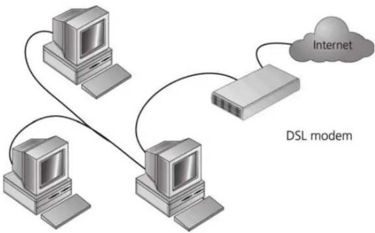
Figure 1 shows an example network without a Router. In this network, only one computer is connected to the Internet. This computer must always be powered on for the other computers on the network to access the Internet.
Figure 1 Example Network Without a Router
flowchart
graph TD
    A["Desktop Computer"] --> B["DSL modem"]
    C["Desktop Computer"] --> B
    D["Desktop Computer"] --> B
    B --> E["Internet"]
    style B fill:#f9f,stroke:#333
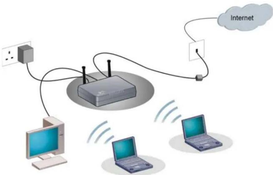
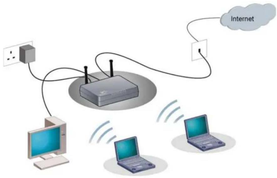
When you use the Router in your network (Figure 2 and Figure 3), it becomes your connection to the Internet. Connections can be made directly to the Router, or to an OfficeConnect Switch or Hub, expanding the number of computers you can have in your network.
Figure 2 Example Network Using a Firewall Router (with splitter)
flowchart
graph TD
    A["Router"] -->|Wireless| B["Computer 1"]
    A -->|Wireless| C["Computer 2"]
    A -->|Wireless| D["Computer 3"]
    A -->|Wireless| E["Internet"]
    E --> F["Cloud"]
    style A fill:#f9f,stroke:#333
    style B fill:#ccf,stroke:#333
    style C fill:#cfc,stroke:#333
    style D fill:#fcc,stroke:#333
    style E fill:#cff,stroke:#333
Figure 3 Example Network Using a Firewall Router (without splitter)
flowchart
graph TD
    A["Router"] -->|Wireless Link| B["Computer 1"]
    A -->|Wireless Link| C["Computer 2"]
    A -->|Wireless Link| D["Computer 3"]
    A -->|Wireless Link| E["Internet"]
    E --> F["Cloud"]
    style A fill:#f9f,stroke:#333
    style B fill:#ccf,stroke:#333
    style C fill:#cfc,stroke:#333
    style D fill:#fcc,stroke:#333
    style E fill:#cff,stroke:#333
Router Advantages The advantages of the Router include:
■Shared Internet connection for both wired and wireless computers
■High speed 802.11n wireless networking
■ No need for a dedicated, "always on" computer serving as your Internet connection
■ Cross-platform operation for compatibility with Windows, Unix and Macintosh computers
■Easy-to-use, Web-based setup and configuration
■Provides centralization of all network address settings (DHCP)
■Acts as a Virtual server to enable remote access to Web, FTP, and other services on your network
■ Security — Firewall protection against Internet hacker attacks and encryption to protect wireless network traffic
Package Contents The Router kit includes the following items:
■One 3Com Wireless 11n ADSL Firewall Router
■One power adapter for use with the Router
■Four rubber feet
■One telephone cable (only for 3CRWDR300A-73 version)
■One Ethernet cable (Two Ethernet cables in 3CRWDR300B-73 version)
■One CD-ROM containing this user guide, copies of the quick install guide in various languages and the 3Com Detect application.
■Installation guide
■Support and Safety sheet
■Warranty sheet
If any of these items are missing or damaged, please contact your retailer.
Minimum System and Component Requirements
Your Router requires that the computer(s) and components in your network be configured with the following:
■A computer with an operating system that supports TCP/IP networking protocols (for example Windows 2000/XP,/Vista, Unix, Mac OS 8.5 or higher).
■An Ethernet 10 Mbps or 10/100 Mbps or 10/100/1000 Mbps NIC for each computer to be connected to the LAN port on your Router.
■An 802.11b, 802.11g or 802.11n draft2.0 compliant wireless NIC.
■An active ADSL subscription and connection.
■A Web browser that supports JavaScript, such as Netscape 4.7 or higher, Internet Explorer 6.0 or higher, or Mozilla 1.2.1 or higher, or Apple's Safari.
Physical Features
The front panel of the Router contains a series of indicator lights (LEDs) that help describe the state of various networking and connection operations.
Figure 4 Router - Front Panel
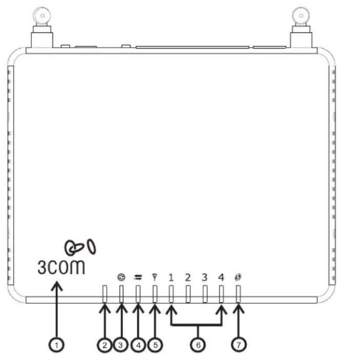
1 Power LED (Illuminated Logo)
White
The 3Com logo serves as power OK indicator. This LED will light if the router is receiving power from the power adapter. If it is not lit check the power adapter connections. Refer to Chapter 6 Troubleshooting.
2 Alert LED
Amber
Fast flash during self test. If self test fails the LED will remain on.
Fast flash during software upgrade.
Fast flash for software reset to the factory defaults.
Fast flash for hardware reset to the factory defaults.
The LED is on for 2 seconds when the firewall detects a hacker attack.
3 A D S L S y n c
Blue
LED on indicates the Internet connection is on. This LED flashes during configuration at power up.
4 A D S L D a t a
Blue
Fast flash means transmitting/receiving data.
Slow flash means ADSL connection is down.
5 Wireless LAN (WLAN) Status LED
Blue
If the LED is on it indicates that wireless networking is enabled. If the LED is flashing, the link is OK and data is being transmitted or received. If the LED is off, the Wireless LAN has been disabled in the Router, or there is a problem. Refer to Chapter 6 Troubleshooting.
6 LAN Status LEDs (4 indicators)
Blue
If the LED is on, the link between the port and the next piece of network equipment is OK. If the LED is flashing, the link is OK and data is being transmitted or received. If the LED is off, nothing is connected, or the connected device is switched off, or there is a problem with the connection (refer to Chapter 6 Troubleshooting). The port will automatically adjust to the correct speed and duplex.
7 WPS LED
Blue
WiFi Protected Setup (WPS) is a standard for easy and secure establishment of a wireless network, allowing wireless clients to connect securely to routers and access points. The WPS LED shows the status of the WPS function. It has a number of modes to help monitor the status of clients connecting to the Router using the WPS protocol. The status is shown by three different flashing rates: slow, medium and quick and when light constantly.
Note: The WPS function will be enabled for 2 minutes once WPS is enabled either by pressing the button or by starting the PIN mode via the web interface. This time will end before 2 minutes if a client has successfully connected. Only one client should be connected to the Router using WPS at any one time. Attempting to connect two or more clients at once may result in connection failures.
When the WPS button is pressed, or WPS is initiated using the PIN method in the web interface, the WPS LED will flash at a medium rate for up to 2 minutes to indicate that a WPS connection can be made. When a connection attempt is underway, the LED will flash slowly.
If the connection has been successful, the WPS LED will remain illuminated for 5 minutes. If the connection attempt has failed, the WPS LED will flash rapidly for 5 minutes. You can re-try the connection by pressing the WPS button, when the connection process will re-start.
If you want to add a further client to the Router, you do not need to wait for the 5 minute period to end. You can press the WPS button (or use the PIN method via the web interface) as soon as the first client is successfully connected.
The rear panel (Figure 5) of the Router contains one ADSL port, four LAN ports, one WiFi on/off button, a reset button, one power adapter socket, and one WPS button.
Figure 5 Router - Rear Panel

1 Wireless Antennae
The antennaes should be placed in a 'V' position when initially installed.

CAUTION: Do not force the antennae beyond their mechanical stops. Rotating the antennae further may cause damage.
2 ADSL Port
RJ-11 port (3CRWDR300A-73)/ RJ-45 port (3CRWDR300B-73), connect this port with the telephone socket.
3 Ethernet Ports (4 ports)
Using suitable RJ-45 cables, you can connect your Router to a computer, or to any other piece of equipment that has an Ethernet connection (for example, a hub or a switch). These ports have an automatic MDI/MDIX feature, which means either straight-through or a crossover cable can be used.
4 WiFi On/Off button
Use this button to turn on/turn off the wireless function. Press the button for 3 seconds.
5 Reset Button
If you want to reset your Router to factory default settings, or cannot access the web management interface (for example, due to a lost password), then you may use this button. Refer to Forgotten Password and Reset to Factory Defaults on page 138 for further details.
6 Power Adapter Socket
Only use the power adapter that is supplied with this Router. Do not use any other adapter.
7 WPS button
Press this button for 3 seconds when making WPS setup. Pushing the WPS button will automatically enable WPS. Then initiate the WPS procedure on the wireless NIC within two minutes. Refer to your wireless NIC's documentation on this procedure. The wireless NIC will then be securely added to your wireless network.
2
INSTALLING THE ROUTER
Introduction
This chapter will guide you through a basic installation of the Router, including:
■Connecting the Router to the Internet.
■Connecting the Router to your network.
■Setting up your computers for networking with the Router.
Safety Information Please note the following:

WARNING: Please read the Safety Information section in Appendix C before you start.

Positioning the Router
You should place the Router in a location that:
■is conveniently located for connection to the telephone socket.
■ is centrally located to the wireless computers that will connect to the Router. A suitable location might be on top of a high shelf or similar furniture to optimize wireless connections to computers in both horizontal and vertical directions, allowing wider coverage.
■allows convenient connection to the computers that will be connected to the four LAN ports on the rear panel, if desired.
■allows easy viewing of the LED indicator lights, and access to the rear panel connectors, if necessary.
When positioning your Router, ensure:
■It is out of direct sunlight and away from sources of heat.
■ Cabling is away from power lines, fluorescent lighting fixtures, and sources of electrical noise such as radios, transmitters and broadband amplifiers.
■Water or moisture cannot enter the case of the unit.
■Air flow around the unit and through the vents in the side of the case is not restricted. 3Com recommends you provide a minimum of 25 mm (1 in.) clearance.
Using the Rubber Feet
Use the four self-adhesive rubber feet to prevent your Router from moving around on your desk or when stacking with flat top units. Only stick the feet to the marked areas at each corner of the underside of your Router.

Please be careful when you put 3Com 11n ADSL Router on top of another unit, if the unit underneath is hot, this may impact the reliability of 3Com 11n ADSL Router.
Wall Mounting
There are two slots on the underside of the Router that can be used for wall mounting. The Router must be mounted with the LEDs facing upwards.

When wall mounting the unit, ensure it is within reach of the power outlet. When wall mounting the unit, ensure that the rubber feet are not fixed.
Mounting Instructions for Cement Walls
To wall mount the unit:
1 Make two holes 98 mm (3.9 in.) apart and insert two nylon or similar screw anchors that are suitable for the wall construction.
2 Fix two suitable screws into the anchors, leaving their heads 3 mm (0.12 in.) clear of the wall surface. The screws should be at least 30 mm (1.2 in.) long.
3 Remove any connections in the Router and locate it over the screw heads. When in line, gently push the Router on to the wall and move it downwards to secure.
Mounting Instructions for Wood Walls
To wall mount the unit:
1 Make two holes 98 mm (3.9 in.) apart.
2 Fix two suitable screws directly into the wall, leaving their heads 3 mm (0.12 in.) clear of the wall surface. The screws should be at least 20 mm (0.75 in.) long.
3 Remove any connections in the Router and locate it over the screw heads. When in line, gently push the Router on to the wall and move it downwards to secure.

CAUTION: When making connections, be careful not to push the unit up and off the wall.
Powering Up the Router
To power up the Router:
1 Plug the power adapter into the power adapter socket located on the back panel of the Router.
2 Plug the power adapter into a standard electrical wall socket.
Connecting the Router
The first step for installing your Router is to physically connect it to the telephone socket and then connect it to a computer in order to be able to access the Internet. See Figure 6 and Figure 7:
Figure 6 Connecting the Router (with splitter)

flowchart
graph TD
    A["Power Hub"] --> B["RRouter"]
    B --> C["Computer"]
    B --> D["Laptop"]
    B --> E["Laptop"]
    B --> F["Internet"]
    style B fill:#f9f,stroke:#333
    style C fill:#ccf,stroke:#333
    style D fill:#cfc,stroke:#333
    style E fill:#fcc,stroke:#333
    style F fill:#cff,stroke:#333
Figure 7 Connecting the Router (without splitter)

flowchart
graph TD
    A["Power Hub"] --> B["RRouter"]
    B --> C["Computer"]
    B --> D["Laptop"]
    B --> E["Laptop"]
    B --> F["Internet"]
1 Run the provided telephone cable from the wall jack providing ADSL service to the ADSL port on your Router. When inserting an ADSL RJ-11(Annex A) or RJ-45 (Annex B) plug, be sure the tab on the plug clicks into position to ensure that it is properly seated. If you are using splitterless ADSL service, add low-pass filters between the ADSL wall jack and your telephones. (These filters pass voice signals through but filter data signals out.)
2 Then:
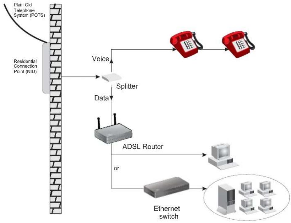
■ If you are using a full-rate (G.dmt) connection, your service provider will attach the outside ADSL line to a data/voice splitter. In this case you can connect your phones and computer directly to the splitter as shown below (Figure 8):
or
■If you are using a splitterless (G.lite) connection, then your service provider will attach the outside ADSL line directly to your phone system. In this case you can connect your phones and computer directly to the incoming ADSL line, but you will have to add low-pass filters to your phones as shown below (Figure 9)
Figure 8 Installing with a splitter
flowchart
graph TD
    A["Plain Old Telephone System (POTS)"] --> B["Residential Connection Point (NID)"]
    B --> C["Voice Splitter"]
    C --> D["ADSL Router"]
    D --> E["Ethernet switch"]
    E --> F["Computer"]
    C --> G["Red Phone 1"]
    C --> H["Red Phone 2"]
    D --> I["White Computer"]
    D --> J["White Tablet"]
    D --> K["White Desktop Computer"]
    style A fill:#f9f,stroke:#333
    style B fill:#ccf,stroke:#333
    style C fill:#cfc,stroke:#333
    style D fill:#fcc,stroke:#333
    style E fill:#cff,stroke:#333
    style F fill:#ffc,stroke:#333
    style G fill:#fcc,stroke:#333
    style H fill:#fcc,stroke:#333
    style I fill:#ffc,stroke:#333
    style J fill:#fcc,stroke:#333
    style K fill:#fcc,stroke:#333
Figure 9 Installing without a splitter

flowchart
graph TD
    A["Plain Old Telephone System (POTS)"] --> B["Residential Connection Point [Network Interface Device (NID)"]]
    B --> C["Filter"]
    C --> D["Voice & Data"]
    D --> E["ADSL Router"]
    E --> F["Data"]
    F --> G["or"]
    G --> H["Ethernet switch"]
    H --> I["Computer"]
    H --> J["Computer"]
    H --> K["Computer"]
You have now completed the hardware installation of your Router. Next you need to set up your computers so that they can make use of the Router to communicate with the Internet.
3Com recommends that you perform the initial Router configuration from a computer that is directly connected to one of the LAN ports.
If you configure the Router from a wireless computer, note that you may lose contact with the Router if you change the wireless configuration.
To communicate wirelessly with your Router, your wireless NIC should be set as follows:
■Encryption — none
■SSID — 3Com
■Channel — 11
3
SETTING UP YOUR COMPUTERS
The Router has the ability to dynamically allocate network addresses to the computers on your network, using DHCP. However, your computers need to be configured correctly for this to take place. To change the configuration of your computers to allow this, follow the instructions in this chapter.
Obtaining an IP Address Automatically
Windows 2000 If you are using a Windows 2000-based computer, use the following procedure to change your TCP/IP settings:
1 From the Windows Start Menu, select Settings > Control Panel.
2 Double click on Network and Dial-Up Connections.
3 Double click on Local Area Connection.
4 Click on Properties.
5 A screen similar to Figure 10 should be displayed. Select Internet Protocol TCP/IP and click on Properties.
Figure 10 Local Area Properties Screen

6 Ensure that the options Obtain an IP address automatically, and Obtain DNS server address automatically are both selected as shown in Figure 11. Click OK.
Figure 11 Internet Protocol (TCP/IP) Properties Screen

7 Restart your computer.
Windows Vista
1 From the Windows Start Menu, select Settings > Network.
2 Click on Organize. Select Properties.
3 Click on Manage network > Connections.
4 Double click Local Area Connection. Select Properties and click continue.
5 A screen similar to Figure 12 should appear. Select Internet Protocol Version 6, Version 4 (TCP/IPv6,v4) and click on Properties.
Figure 12 Local Area Connection Properties Screen

6 Ensure that the options Obtain an IPv6,v4 address automatically, and Obtain DNS servers address automatically are both selected as shown in Figure 13. Click OK.
Figure 13 Internet Protocol Version 6 (TCP/IPv6) Properties Screen

Windows XP
1 From the Windows Start Menu, select Control Panel.
2 Click on Network and Internet Connections.
3 Click on the Network Connections icon.
4 Double click on LAN or High Speed Connection icon. A screen titled Local Area Connection Status will appear.
5 Select Internet Protocol TCP/IP and click on Properties.
6 Ensure that the options Obtain an IP address automatically, and Obtain DNS servers automatically are both selected. Click OK.
7 Restart your computer.
Macintosh If you are using a Macintosh computer, use the following procedure to change your TCP/IP settings:
1 From the desktop, select Apple Menu, Control Panels, and TCP/IP.
2 In the TCP/IP control panel, set Connect Via: to Ethernet.
3 In the TCP/IP control panel, set Configure: to Using DHCP Server.
4 Close the TCP/IP dialog box, and save your changes.
5 Restart your computer.
Disabling PPPoE and PPTP Client Software
If you have PPPoE client software installed on your computer, you will need to disable it. To do this:
1 From the Windows Start Menu, select Settings > Control Panel.
2 Double click on Internet Options.
3 Select the Connections Tab. A screen similar to Figure 14 should be displayed.
4 Select the Never dial a connection option.
Figure 14 Internet Properties Screen


You may want to remove the PPPoE client software from your computer to free resources, as it is not required for use with the Router.
Disabling Web Proxy
Ensure that you do not have a web proxy enabled on your computer.
Go to the Control Panel and click on Internet Options. Select the Connections tab and click LAN Settings at the bottom. Make sure that the Use Proxy Server option is unchecked.
CHAPTER 3: SETTING UP YOUR COMPUTERS
4
RUNNING THE SETUP WIZARD
| Accessing the Router using the 3Com Detect Application | The 3Com Detect application works by automatically locating your Router, establishing what IP address it is using and then launching your default web browser to connect directly to it.The application will only locate your Router if it is on the same subnet as the PC on which the application is running. It will not be able to locate your Router if there is another router between your PC and the Router. Note that the 3Com detect application isonlydesigned to run on Windows operating systems. |
| Running the 3Com Detect Application | The CD-ROM that comes with this Router contains, in addition to the documentation, the 3Com Detect Application.To use 3Com Detect to connect to the Web interface of your Router, do the following:On the computer that is connected to your Router (either directly or on a network that is on the same subnet), insert the CD-ROM into its CD drive. If you have autorun enabled, you will be presented with a menu showing the contents of the CD-ROM. Select the 3Com Detect Application link to install the utility. Follow the onscreen instructions.If the auto-run program does not start, you should browse to your CD-ROM drive, go to the /3Com detect directory and double click on setup.exe. Follow the prompts that will take you through the installation process.Once installed, the 3Com Detect Application can be accessed from the Windows Start/Programs list.When the 3Com Detect application starts, you will see the Welcome Screen, seeFigure 15. |
Figure 15 3Com Detect Application
![3Com Deler v2.1 Welcome This application will help you to find and configure your 3Com product. Please select the network interface that your product is connected to: [Form:57.182.050.64/Chival Network Convection - P] IP address of adopter: 192.168.1.3 上一步(B) 下一步(N) > 取消](/content/2026/05/987559/images/64d2d45dfd14ebc83ac864b5d8efd55233b7cb4b94b32d86812227c29fca85a7.jpg)
If the computer has multiple network adapters, select the adapter that connects the computer to the network or the Router, click Next.
You will then be offered the choice of searching the same subnet that your PC is on for a connected Router (default), or specifying an IP range. Note that specifying a large range may take some time for the search to complete (see Figure 16 and Figure 17).
Figure 16 Discovery Screen - search the same subnet
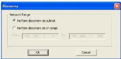
Figure 17 Discovery Screen - search IP range

Once your Router has been located, you will see the list (see Figure 18). Select the Router to which you want to connect and click Open. Your default Web browser will launch and connect to the home page of the Router, see Figure 20.
Figure 18 Router List Screen

Accessing the Setup Wizard
The Router setup program is Web-based, which means that it is accessed through your Web browser (Netscape Navigator 4.7 or higher, Internet Explorer 6.0 or higher, or Mozilla 1.2.1 or higher, or Apple's Safari).
To use the Setup Wizard:
1 Ensure that you have at least one computer connected to the Router. Refer to Chapter 2 for details on how to do this.
2 Launch your Web browser on the computer.
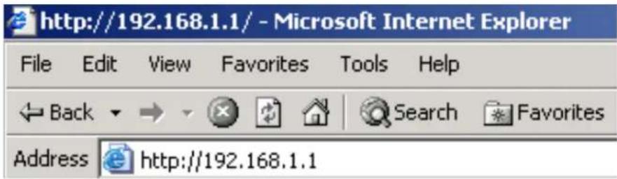
3 Enter the following URL in the location or address field of your browser: http://192.168.1.1 (Figure 19). The Login screen displays.
Figure 19 Web Browser Location Field (Factory Default)
4 To log in as an administrator, enter the password (the default password is admin) in the System Password field and click Log in (see Figure 20).
Figure 20 Router Login Screen

5 When you have logged in,
■ if you are logging in for the first time, the Country Selection screen will appear (see Figure 21). Please select the country form the drop-down menu, and click Apply.
-
To comply with US FCC regulations, operation for any country is limited to channels from 1 to 11.
-
Customers outside of the US, Canada or Taiwan can download the firmware from the 3Com website (www.3com.com) which will enable operation on channels 12-13. You will be asked to verify your country before you can download the firmware what will enable the wider range of channels to be used.
Figure 21 Country Selection Screen

The Wizard will then launch automatically (refer to Figure 24). You will be guided step by step through a basic setup procedure.
■ if the Router has been configured previously, the Welcome screen will appear (Figure 22). There are three tabs: Notice Board, Password and Wizard.
Figure 22 Welcome Screen

- Go to the Notice Board tab to see the current software information. To view the Web help, click the Help button.
■ Go to the Password tab to change the password (Figure 23).
■ Go to the Wizard tab to do a quick setup of the Router (Figure 24).
The password screen allows you to change the current password and set the login time limit to the Router's management interface.
Figure 23 Password Screen
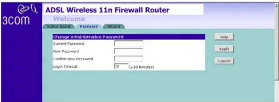
1 To change the current password, enter the password in the Current Password field.
2 Enter the new password in the New Password field, and enter it again in the Confirm New Password field.
3 Enter the time period in Login Timeout to set a maximum period of time for which the login session is maintained during inactivity (default: 10 minutes). Then click Apply.
Wizard - Change Password
To ensure the security of your Router, it is recommended that you choose a new password - this should be a mix of letters and numbers, and not easily guessed by others. To leave the current password unchanged, leave the fields blank and click Next.
Figure 24 Change Password Screen

Wizard - Time and Time Zone
The Time and Time Zone screen allows you to set up the time for the Router.
Figure 25 Time and Time Zone Screen

1 Select the correct base date and time.
2 If you want to automatically synchronize the Router with a public time server, check the Enable box in the Using Time Server (NTP) field.
3 Select the time zone in the Set Time Zone drop-down menu.
4 Enter the time in the Synchronization Interval field.
5 Select the desired servers from the Time Server drop-down menu.
6 Check the Enable box in the Daylight Savings field, if daylight savings applies to your area.
7 Click Next.
Wizard - Connection Type
The Connection Type screen allows you to set up the Router for the type of Internet connection you have. Before setting up your connection type, have your account information from your ISP ready.
Figure 26 Connection Type Screen
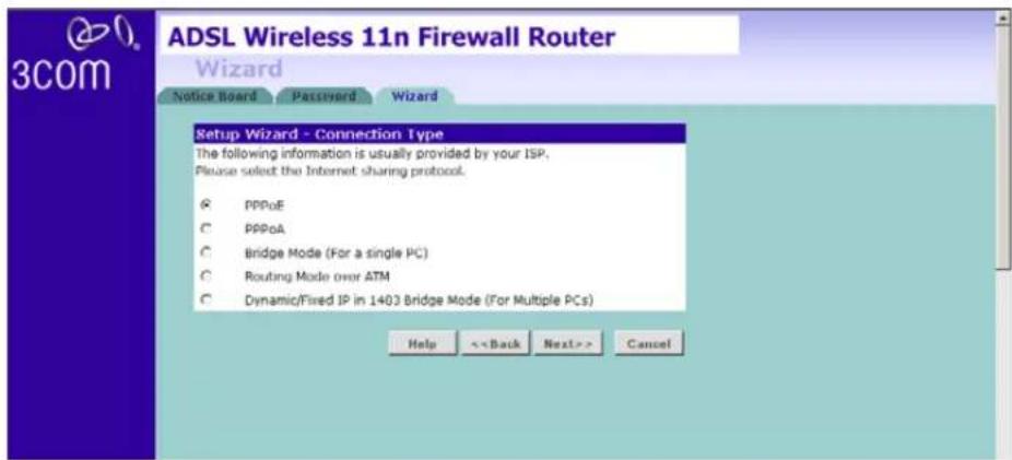
Select a mode from the following options, and click Next:
■ PPPoE — PPP over Ethernet, providing routing for multiple PCs, see page 41
■ PPPoA — PPP over ATM, providing routing for multiple PCs, see page 42
■ Bridge Mode (for a single PC) — RFC1483 Bridged Mode, see page 43
■ Routing Mode over ATM — RFC1483 Routed Mode, for multiple PCs, see page 44
■ Dynamic/Fixed IP in 1483 Bridge Mode (For Multiple PCs) — see page 45

For further information on selecting a mode see Internet Settings on page 76.
PPPoE
PPPoE is often used for DSL connection. To set up the Router for use with a PPPoE (PPP over Ethernet) connection, use the following procedure:
Figure 27 PPPoE Screen

1 Enter your user name in the Username field.
2 Enter your password in the Password field.
3 Re-type your password in the Retype Password field.
4 Enter your VPI and VCI information in the VPI/VCI fields.
5 Select the encapsulation type (LLC or VC MUX) in the Encapsulation drop-down menu. This information should be provided to you by your ISP.
Check all of your settings, and then click Next.
The LAN Settings screen will then be displayed (refer to Figure 32).
PPPoA
To set up the Router for use with a PPP over ATM (PPPoA) connection, use the following procedure:
Figure 28 PPPoA Screen

1 Enter your user name in the Username field.
2 Enter your password in the Password field.
3 Re-type your password in the Retype Password field.
4 Enter your VPI and VCI information in the VPI/VCI fields.
5 Select the encapsulation type (LLC or VC MUX) in the Encapsulation drop-down menu. This information should be provided to you by your ISP.
Check all of your settings, and then click Next. The LAN Settings screen will then be displayed (refer to Figure 32).
Bridge Mode (for a single PC)
Selecting the Bridge mode sets the device into 1483 bridging mode in which the device connects LANs and WAN together. It operates as a Data Link Layer device that acts to limit the traffic between two network segments by filtering the data between them based on the hardware address.
To set up the Router for use with an RFC1483 bridged connection, use the following procedure:
Figure 29 Bridged Mode Screen

1 Enter your VPI and VCI information in the VPI/VCI fields.
2 Select the encapsulation type (LLC or VC MUX) in the Encapsulation drop-down menu. This information should be provided to you by your ISP.
Check all of your settings, and then click Next.
The LAN Settings screen will then be displayed (refer to Figure 32).
Routing Mode over ATM
The Routing Mode over ATM uses fixed/static IP addresses, which are provided by your ISP, to connect to the Internet. Obtain the information on this screen from your ISP.
Figure 30 Routing mode over ATM Screen
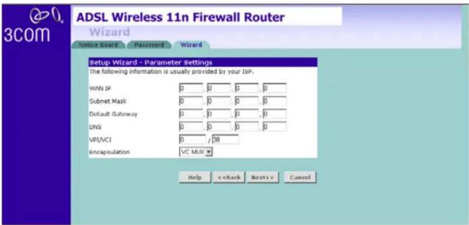
1 Enter your Internet IP address in the WAN IP field.
2 Enter the subnet mask in the Subnet Mask field.
3 Enter the default gateway IP address in the Default Gateway field.
4 Enter the DNS address in the DNS field.
5 Enter your VPI and VCI information in the VPI/VCI fields.
6 Select the encapsulation type (LLC or VC MUX) in the Encapsulation drop-down menu. This information should be provided to you by your ISP.
Check all of your settings, and then click Next. The LAN Settings screen will then be displayed (refer to Figure 32).
Dynamic/Fixed IP in 1483 Bridge Mode (For Multiple PCs)
For bridge mode to work, you need to assign an IP address to the Router. You can either configure the Router to obtain an IP address automatically from a DHCP server or assign a fixed or static IP address to it.
Figure 31 Dynamic/Fixed IP for Bridge Mode Screen
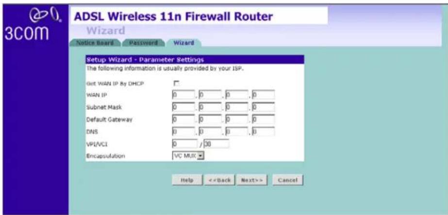
■To obtain an IP address automatically from a DHCP server: check the Get WAN IP By DCHP checkbox, and then click Next.
■To assign a fixed IP address:
1 Enter your IP address in the WAN IP field.
2 Enter the subnet mask in the Subnet Mask field.
3 Enter the default gateway IP address in the Default Gateway field.
4 Enter the DNS address in the DNS field.
5 Enter your VPI and VCI information in the VPI/VCI fields.
6 Select the encapsulation type (LLC or VC MUX) in the Encapsulation drop-down menu. This information should be provided to you by your ISP.
Check all of your settings, and then click Next.
The LAN Settings screen will then be displayed (refer to Figure 32).
Wizard - LAN Settings
The LAN Settings screen allows you to set the default IP address and DHCP client IP range for the Router.
Figure 32 The LAN Settings Screen

1 To change the Router's default IP address, enter the new IP address in the IP Address field, and then enter the subnet mask in the Subnet Mask field.
2 Check the Enable DHCP Server box to enable the DHCP function.
3 Enter the client IP address range in the IP Pool Start Address and IP Pool End Address fields. You can also click Auto IP Range to automatically set the starting and ending IP address: 192.168.1.2 \~ 192.168.1.254.
4 Click Next. The Wireless Settings screen will appear (refer to Figure 33).
Wizard - Wireless Setting
The Wireless Settings screen allows you to set up the SSID and radio channel used for the wireless connection.
Figure 33 Wireless Setting Screen

1 Select the channel you want to use from the Channel drop-down menu.
2 Specify the SSID to be used by your wireless network in the SSID field. If there are other wireless networks in your area, you should give your wireless network an unique name.
For advanced settings, please click Wireless Settings on the left menu bar after completing this Setup Wizard setting.
3 Click Next. The security mode screen appears.
Security Mode
Select the Security Mode, five options available:
■Disabled: in this mode, wireless transmissions will not be encrypted, and will be visible to everyone. However, when setting up or debugging wireless networks, it is often useful to use this security mode.
■64-bit WEP, see page 48
■ 128-bit WEP, see page 49
■WPA-PSK (no server), this mode includes WPA and WPA2, see page 50
■WPA (with Radius Server), this mode includes WPA and WPA2, see page 51
Figure 34 Security Mode Screen

64-bit WEP
WEP is the basic mechanism to transmit your data securely over the wireless network. Matching encryption keys must be setup on your Router and wireless client devices to use WEP.
Figure 35 64-bit WEP Screen
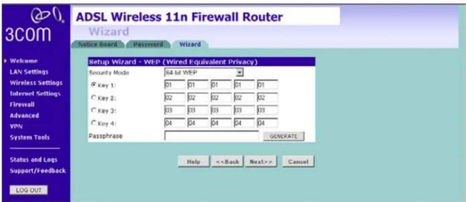
To enable 64-bit WEP:
1 You can enter the 64-bit WEP key manually. Enter the WEP key as 5 pairs of hex digits (0-9, A-F). Or you can generate the 64-bit WEP key automatically. Enter a memorable passphrase in the Passphrase box, and then click Generate to generate the hex keys from the passphrase.
For 64-bit WEP, you can enter up to four keys, in the fields Key 1 to Key 4. The radio button on the left hand side selects the key that is used in transmitting data.
2 Click Next.
Note that all four WEP keys on each device of the same wireless network must be identical.
128-bit WEP
WEP is the basic mechanism to transmit your data securely over the wireless network. Matching encryption keys must be set up on your Router and wireless client devices to use WEP.
Figure 36 128-bit WEP

To enable 128-bit WEP:
1 You can enter the 128-bit WEP key manually, enter your WEP key as 13 pairs of hex digits (0-9, A-F). Or you can generate the 128-bit WEP key automatically, enter a memorable passphrase in the Passphrase box, and then click Generate to generate the hex keys from the passphrase.
2 Click Next.
Note that the WEP keys on each device of the same wireless network must be identical. And In 128-bit WEP mode, only one WEP key can be specified.
WPA-PSK (no server)
WPA (Wi-Fi Protected Access) provides dynamic key changes and constitutes the best security solution. If your network does not have a RADIUS server. Select the no server option. Note that in home and very small office deployments, PSK is typically used.
Figure 37 WPA-PSK no server Screen
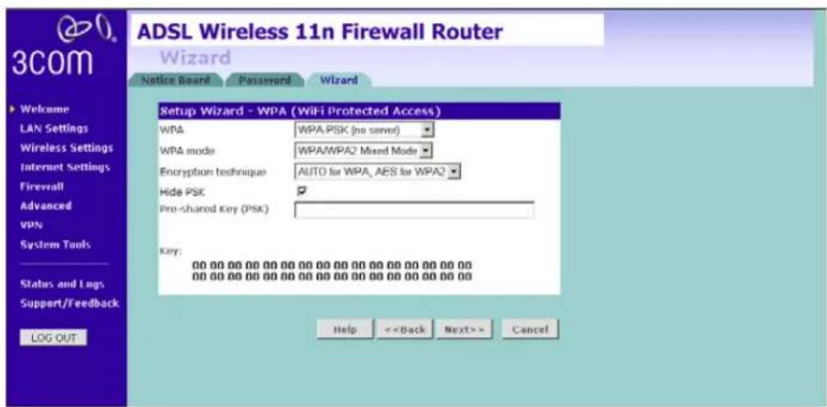
1 Select WPA-PSK (no server) from the WPA drop-down menu.
2 Select WPA mode from the drop-down menu, three modes are supported: WPA, WPA2, and Mixed mode.
3 Select Encryption technique from the drop-down menu, four options are available: TKIP, AES, Auto for WPA AES for WPA2, and AES for both WPA and WPA2.
WPA supports TKIP and AES Encryption technique, for some old module of wireless client cards, they may only support TKIP. In this case, we suggest you to select "AUTO for WPA, AES for WPA2". If your wireless client cards can support AES over WPA, we suggest you directly select "AES for both WPA and WPA2".
4 Enter the pre-shared key in the Pre-shared Key (PSK) field. The pre-shared key is a password, in the form of a word, phrase or series of letters and numbers. The key must be between 8 and 63 characters long and can include spaces and symbols. Each client that connects to the network must use the same key.
5 If you want the key that you enter to be shown on the screen as a series of asterisks (*), then check the Hide PSK checkbox.
6 Click Next.
WPA with Radius Server
WPA (Wi-Fi Protected Access) provides dynamic key changes and constitutes the best security solution. This function requires that a RADIUS server is running on the network.
Figure 38 WPA with Radius Server Screen

1 Select WPA with RADIUS server from the Security Mode drop-down menu.
2 Select WPA mode from the drop-down menu, three modes are supported: WPA, WPA2, and Mixed mode.
3 Select Encryption technique from the drop-down menu, four options are available: TKIP, AES, Auto for WPA AES for WPA2, and AES for both WPA and WPA2.
WPA supports TKIP and AES Encryption technique, for some old module of wireless client cards, they may only support TKIP. In this case, we suggest you to select "AUTO for WPA, AES for WPA2". If your wireless client cards can support AES over WPA, we suggest you directly select "AES for both WPA and WPA2".
4 Enter the IP address of the RADIUS server on your network into the RADIUS Server field.
5 Enter the Radius Port number that the RADIUS server is operating on.
6 Enter the key for the RADIUS server in the Radius Key field.
7 By default, the WPA keys are changed every hour, but if you want to change this setting, you can do so by specifying the rotation time in the Re-key Interval field.
8 Click Next.
Wizard - Configuration Summary
When you have completed the Setup Wizard, a configuration summary will appear. Verify the configuration information of the Router and then click Apply to save your settings. 3Com recommends that you print out this page for your records.
Figure 39 Configuration Summary Screen

Your Router is now configured and ready for use.
See Chapter 5 for a further detailed description of the Router configuration.
5
CONFIGURING THE ROUTER
| Navigating through the Router Configuration Screens | This chapter describes all the screens available through the Router configuration screens, and is provided as a reference. To get to the configuration screens, enter the Router's default IP in the location bar of your browser. The default IP is http://192.168.1.1.However, if you changed the Router LAN IP address during initial configuration, use the new IP address instead. Enter your password to login to the management interface. (The default password is admin). |
| Main Menu | The main menu is located on the left side, as shown in Figure 40. When you click on an item from the main menu, the corresponding screen will then appear in the center. |
Welcome Screen
The Welcome screen shows the current software information.
Status
Figure 40 Welcome Screen

LAN Settings
Your Router is equipped with a DHCP server that will automatically assign IP addresses to each computer on your network. The factory default settings for the DHCP server will work with most applications. If you need to make changes to the settings, you can do so.
The LAN settings screen allows you to:
■Change the default IP address of the Router. The default IP is 192.168.1.1
■ Change the Subnet Mask. The default setting is 255.255.255.0
■ Enable/Disable the DHCP Server Function. The default is: Enable.
■Specify the Starting and Ending IP Pool address. The default is Starting: 2 / Ending: 254.
■Specify the IP address Lease Time. The default is One day.
■ Specify a local Domain Name. This field is optional.
■Specify the IP address of 3Com NBX call processor.
The Router will also provide a list of all client computers connected to the Router.
LAN Settings Unit Configuration
The LAN Settings unit configuration screen is used to specify the LAN IP address of your Router, and to configure the DHCP server.
Figure 41 LAN Settings Unit Configuration Screen

1 Enter the Router's IP Address and Subnet Mask in the appropriate fields. The default IP address is 192.168.1.1.
2 If you want to use the Router as a DHCP Server, check Enable in the DHCP Server field.
3 Enter the IP address range in the IP Pool Start Address and IP Pool End Address fields.
4 Specify the DHCP Lease time by selecting the required value from the Lease Time drop-down menu. The lease time is the length of time the DHCP server will reserve the IP address for each computer.
5 Specify the Local Domain Name for your network (this step is optional).
6 Enter the IP address of the NBX Call Processor in the 3Com NBX Call Processor field (this step is optional).
7 Check all of your settings, and then click Apply.
DHCP Clients List
The DHCP Clients List provides details on the devices that have received IP addresses from the Router. The list is only created when the Router is set up as a DHCP server. A maximum of 253 clients can be connected to the Router.
Figure 42 DHCP Clients List Screen

For each device that is connected to the LAN, the following information is displayed:
■ IP address — The Internet Protocol (IP) address issued to the client machine.
■ Host Name — The client machine's host name, if configured.
■ MAC Address — The Media Access Control (MAC) address of the client's network card.
■ Client Type — Whether the client is connected to the Router by wired or wireless connection.
■ Check the Fix checkbox to permanently fix the IP address.
■ Click Release to release the displayed IP address.
- Click Add to allocate an IP address to a MAC address. Enter the required details and click Apply to save your settings.

The DHCP server will give out addresses to both wired and wireless clients.
Wireless Settings
The Wireless Settings screens allow you to configure the settings for the wireless connections.
You can enable or disable the wireless connection for your LAN. When disabled, no wireless PCs can gain access to either the Internet or other PCs on your wired or wireless LAN through this Router.
Figure 43 Wireless Settings Screen
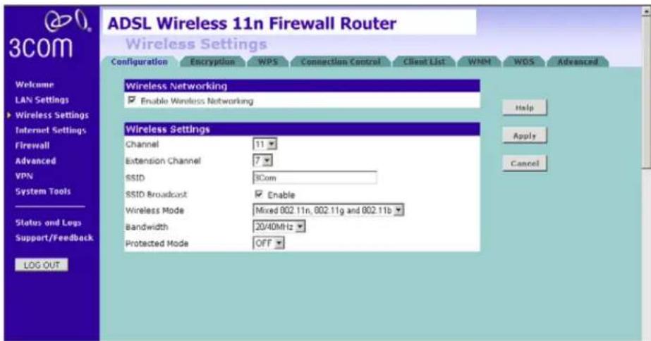
There are 8 tabs available:
■Configuration
■Encryption
■WPS
■Connection Control
■Client List
■WMM
■WDS
■Advanced
Configuration The Wireless Configuration Screen allows you to turn on/ turn off the wireless function, and set up basic wireless settings. You can also enable/disable the Wireless function using the WiFi on/off button at the back of the Router.
Figure 44 Wireless Configuration Screen
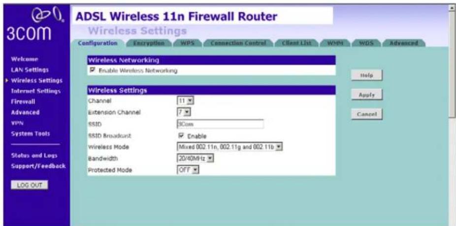
To enable the wireless function:
1 Check Enable Wireless Networking checkbox.
2 Select the wireless channel you want to use from the Channel drop-down menu.
3 Select the Extension Channel.
4 Specify the SSID to be used by your wireless network in the SSID field. If there are other wireless networks in your area, you should give your wireless network an unique name.
5 Enable or disable SSID Broadcast.
A feature of many wireless network adapters is that a computer's SSID can be set to ANY, which means it looks randomly for any existing wireless network. The available networks are then displayed in a site survey, and your computer can select a network. If you disable this SSID broadcast function, you can block this random search, and set the computer's SSID to a specific network (for example, WLAN). This increases network security. If you decide to disable SSID Broadcast, ensure that you know the name of your network first.
6 Select whether your Router will operate in 11b mode only, 11g mode only, 11n mode only, or mixed mode from the Wireless Mode drop-down menu. If your network contains 11b, 11g, and 11n clients, select the mixed mode. If your network contains just one type of clients only, select 11b only, or 11g only, or 11n only, depending on your wireless network environment. Note that selecting one type of wireless network only will improve the performance, however, this will prevent clients of other type from connecting to the Router.
7 Bandwidth: select the bandwidth to use. Select 20/40 MHz when your wireless mode is 802.11n or 11n with 11b, 11 g mixed mode. If your wireless network is purely 11b only or 11g only, or 11b and 11g mixed, select 20 MHz.
8 Select to turn on/off the Protected Mode function. As part of the 802.11g & 802.11n specification, Protected mode ensures proper operation of 802.11g & 802.11n clients and access points when there is heavy 802.11b traffic in the operating environment. When protected mode is ON, 802.11g & 802.11n scans for other wireless network traffic before it transmits data. Therefore, using this mode in environments with HEAVY 802.11b traffic or interference achieves best performance results. If you are in an environment with very little, or no other wireless network traffic, your best performance will be achieved with Protected mode OFF.
9 Click Apply.
Encryption This feature prevents any non-authorized party from reading or changing your data over the wireless network.
Figure 45 Encryption Screen

Select the wireless security mode that you want to use from the drop-down menu, and click Apply. There are five selections:
■Disabled
■ 64-bit WEP (see page 61)
■ 128-bit WEP (see page 62)
■WPA-PSK (no server): this option includes both WPA and WPA2 (see page 63)
■WPA (with RADIUS Server): this option includes both WPA and WPA2 (see page 64)
Disabled
In this mode, wireless transmissions will not be encrypted, and will be visible to everyone. However, when setting up or debugging wireless networks, it is often useful to use this security mode.
64-bit WEP
WEP is the basic mechanism to transmit your data securely over the wireless network. Matching encryption keys must be setup on your Router and wireless client devices to use WEP. Note that 3Com recommends using WPA/WPA2 to secure your wireless connection.
Figure 46 64-bit WEP Screen

To setup 64-bit WEP:
1 You can enter the 64-bit WEP key manually:
■enter the WEP key as 5 pairs of hex digits (0-9, A-F).
Or you can generate the 64-bit WEP key automatically:
■ enter a memorable passphrase in the Passphrase field, and then click Generate to generate the hex keys from the passphrase.
For 64-bit WEP, you can enter up to four keys, in the fields Key 1 to Key 4. The radio button on the left hand side selects the key that is used in transmitting data.

Note that all four WEP keys on each device in the wireless network must be identical.
2 Click Apply.
128-bit WEP
WEP is the basic mechanism to transmit your data securely over the wireless network. Matching encryption keys must be set up on your Router and wireless client devices to use WEP. Note that 3Com recommends using WPA/WPA2 to secure your wireless connection.
Figure 47 128-bit WEP Screen

To setup 128-bit WEP:
1 You can enter the 128-bit WEP key manually:
■enter your WEP key as 13 pairs of hex digits (0-9, A-F).
Or you can generate the 128-bit WEP key automatically:
■ enter a memorable passphrase in the Passphrase field, and then click Generate to generate the hex keys from the passphrase.

The WEP keys on each device on the wireless network must be identical. In 128-bit WEP mode, only one WEP key can be specified.
2 Click Apply.
WPA-PSK (no server)
WPA (Wi-Fi Protected Access) provides dynamic key changes and constitutes the best security solution. If your network does not have a RADIUS server. Select the no server option. For home network or very small business networking environment, PSK is typically used.
Figure 48 WPA-PSK (no server) Screen

1 Select WPA-PSK (no server) from the WPA drop-down menu.
2 Select WPA mode from the drop-down menu, three modes are supported: WPA, WPA2, and Mixed mode.
3 Select Encryption technique from the drop-down menu, four options are available: TKIP, AES, Auto for WPA AES for WPA2, and AES for both WPA and WPA2.
WPA supports TKIP and AES Encryption technique, for some old module of wireless client cards, they may only support TKIP. In this case, we suggest you to select "AUTO for WPA, AES for WPA2". If your wireless client cards can support AES over WPA, we suggest you directly select "AES for both WPA and WPA2".
4 Enter the pre-shared key in the Pre-shared Key (PSK) field. The pre-shared key is a password, in the form of a word, phrase or series of letters and numbers. The key must be between 8 and 63 characters long and can include spaces and symbols. Each client that connects to the network must use the same key.
5 If you want the key that you enter to be shown on the screen as a series of asterisks (*), then check the Hide PSK checkbox.
6 Click Apply.
WPA (with RADIUS Server)
WPA (Wi-Fi Protected Access) provides dynamic key changes and constitutes the best security solution. This function requires that a RADIUS server is running on the network.
Figure 49 WPA (with RADIUS Server) Screen
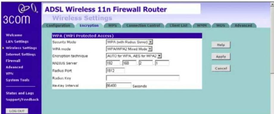
1 Select WPA with RADIUS server from the Security Mode drop-down menu.
2 Select WPA mode from the drop-down menu, three modes are supported: WPA, WPA2, and Mixed mode.
3 Select Encryption technique from the drop-down menu, four options are available: TKIP, AES, Auto for WPA AES for WPA2, and AES for both WPA and WPA2.
WPA supports TKIP and AES Encryption technique, for some old module of wireless client cards, they may only support TKIP. In this case, we suggest you to select "AUTO for WPA, AES for WPA2". If your wireless client cards can support AES over WPA, we suggest you directly select "AES for both WPA and WPA2".
4 Enter the IP address of the RADIUS server on your network into the RADIUS Server field.
5 Enter the port number that the RADIUS server is operating on in the RADIUS Port field.
6 Enter the key for the RADIUS server in the RADIUS Key field.
7 By default, the WPA keys are changed every hour, but if you want to change this setting, you can do so by specifying the required time in the Re-key Interval field.
8 Click Apply.
WPS Wi-Fi Protected Setup (WPS) integrates the new WLAN clients into your wireless network easily. You can enable this function by entering the PIN code via the web UI page or by pressing the WPS button on the rear side of the device.
Figure 50 WPS Screen
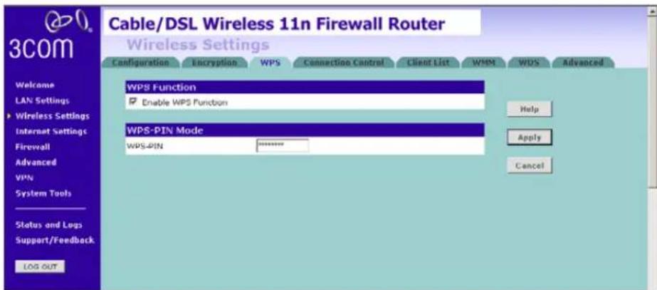
Two methods to setup the WPS, you can choose either one of the following method. Note that if you choose to use the PBC mode, then it would be no need to enter the PIN code of the wireless NIC on this screen.
PIN
1 Check the Enable WPS Function box. The WPS-PIN field will appear.
2 Enter the PIN code in the WPS-PIN field. And then click Apply.
Please note that the PIN code is generated this way: on the client side, run the WPS utility which is provided by the vendor of your Wi-Fi card and select the PIN method. You should get an 8-digit PIN number from the WPS utility.
Enter that 8-digit PIN number on this screen and click Apply to activate this PIN method. Then the Router starts to negotiate the security with the WLAN clients and WPS LED will start flashing. After the connection has been established successfully, the WPS LED will then be off.
■WPS-PBC
1 Press the WPS button located on the rear of the Router. Note that this setup process will only be active for 2 minutes. Follow the instruction of your WLAN NIC to set up the WPS.
The WPS LED shows the status of the WPS function. It has a number of modes to help monitor the status of clients connecting to the Router using the WPS protocol. The status is shown by three different flashing rates: slow, medium and quick and when light constantly.
When the WPS button is pressed, or WPS is initiated using the PIN method in the web interface, the WPS LED will flash at a medium rate for up to 2 minutes to indicate that a WPS connection can be made. When a connection attempt is underway, the LED will flash slowly.
If the connection has been successful, the WPS LED will remain illuminated for 5 minutes. If the connection attempt has failed, the WPS LED will flash rapidly for 5 minutes. You can re-try the connection by pressing the WPS button, when the connection process will re-start.
If you want to add a further client to the Router, you do not need to wait for the 5 minute period to end. You can press the WPS button (or use the PIN method via the web interface) as soon as the first client is successfully connected.
Note: The WPS function will be enabled for 2 minutes once WPS is enabled either by pressing the button or by starting the PIN mode via the web interface. This time will end before 2 minutes if a client has successfully connected. Only one client should be connected to the Router using WPS at any one time. Attempting to connect two or more clients at once may result in connection failures.
Connection Control
This feature is used to filter the clients based on their MAC addresses. Using this function, you can limit the access right of the wireless clients to this Router.
Check the Enable MAC Address Filtering checkbox, the Connection Control screen will appear.
Figure 51 Connection Control Screen

There are two options available in the Access rule for registered MAC address field:
■ if you click Allow, this means only the MAC addresses registered here in the list will be allowed to access the Router via wireless link.
■ if you click Deny, this means the registered MAC addresses will not be able to access the Router via wireless link.
Use the MAC Address Filtering List to quickly copy the MAC addresses of the current wireless clients into the list table. You can define up to 32 MAC addresses to the list.
You can click Clear to delete the current entry in the list.
Client List You can view the list of all wireless clients that are connected to the Router.
Figure 52 Client List Screen
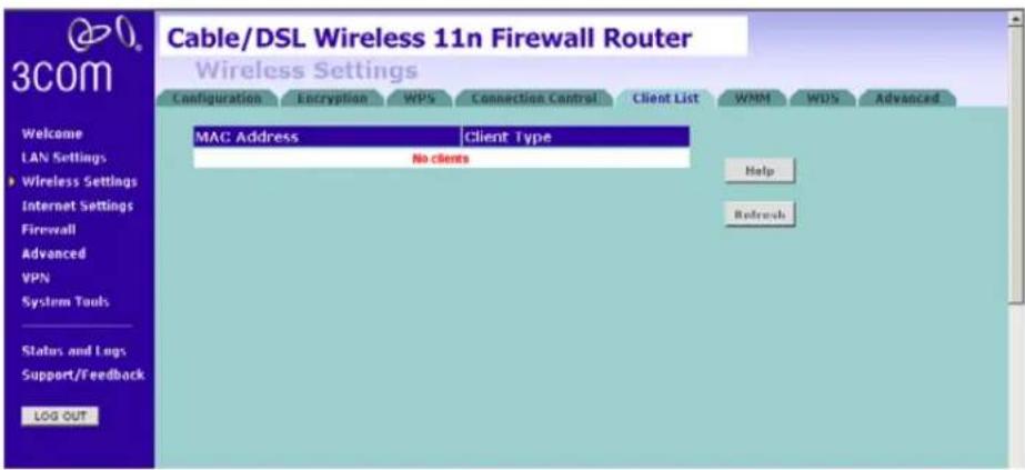
Click Refresh to update the list.
WMM Wireless Multimedia (WMM) mode, which supports devices that meet the 802.11E QBSS standard. WMM uses traffic priority based on the four ACs; Voice, Video, Best Effort, and Background. The higher the AC priority, the higher the probability that data is transmitted.
Check the Enable WMM Function box, the WMM parameters table appears.
Figure 53 WMM Screen

Access Categories – WMM defines four access categories (ACs): voice, video, best effort, and background. These categories correspond to traffic priority levels and are mapped to IEEE 802.1D priority tags. The direct mapping of the four ACs to 802.1D priorities is specifically intended to facilitate inter-operability with other wired network QoS policies. While the four ACs are specified for specific types of traffic, WMM allows the priority levels to be configured to match any network-wide QoS policy. WMM also specifies a protocol that access points can use to communicate the configured traffic priority levels to QoS-enabled wireless clients.
The following table explains the four access categories:
| Access Category WMM Designation | Description | 802.1D Tags |
| AC_BE (AC0) Best Effort Normal priority, medium delay and throughput. Data only affected by long delays. Data from applications or devices that lack QoS capabilities. | 0, 3 | |
| AC_BK (AC1) Background Lowest priority. Data with no delay or throughput requirements, such as bulk data transfers. | 2, 1 | |
| AC_VI (AC2) Video High priority, minimum delay. Time-sensitive data such as streaming video. | 5, 4 | |
| AC_VO (AC3) Voice Highest priority, minimum delay. Time-sensitive data such as VoIP (Voice over IP) calls. | 7, 6 | |
AIFS (Arbitration Inter-Frame Space) – The minimum amount of wait time before the next data transmission attempt. Specify the AIFS value in the range 0-15 microseconds.
CWMax (Maximum Contention Window) – The maximum upper limit of the random backoff wait time before wireless medium access can be attempted. The contention window is doubled after each detected collision up to the CWMax value. Specify the CWMax value in the range 0-15 microseconds. Note that the CWMax value must be greater or equal to the CWMin value.
CWMin (Minimum Contention Window) – The initial upper limit of the random backoff wait time before wireless medium access can be attempted. The initial wait time is a random value between zero and the CWMin value. Specify the CWMin value in the range 0-15 microseconds. Note that the CWMin value must be equal or less than the CWMax value.
TXOP Limit (Transmit Opportunity Limit) – The maximum time an AC transmit queue has access to the wireless medium. When an AC queue is granted a transmit opportunity, it can transmit data for a time up to the TxOp Limit. This data bursting greatly improves the efficiency for high data-rate traffic. Specify a value in the range 0-65535 microseconds.
ACM – Admission Control Mode, for the access category. When enabled, clients are blocked from using the access category. (Default: Disabled)
Ack Policy (WMM Acknowledge Policy) – By default, all wireless data transmissions require the sender to wait for an acknowledgement from the receiver. WMM allows the acknowledgement wait time to be turned off for each Access Category (AC). Although this increases data throughput, it can also result in a high number of errors when traffic levels are heavy. (Default: Acknowledge)
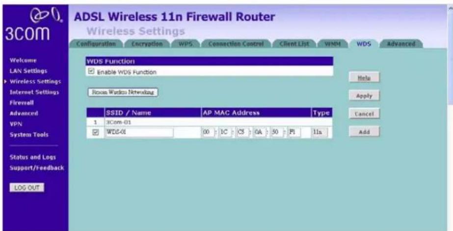
WDS The Router supports WDS (Wireless Distribution System). WDS enables one or more Access Points to rebroadcast received signals to extend range and reach, though this can affect the overall throughput of data.
Note that WDS implementation can vary from product to product. Hence there is no guarantee that different products will interoperate. In addition, the security settings for WDS links should be the same as the one set up for your wireless clients.
Figure 54 Wireless WDS Settings Screen

1 Check the Enable WDS Function checkbox.
2 To refresh the list of available access points, click Rescan Wireless Networking. If the MAC address of the desired APs is in the list of scanned APs, you can simply check those APs to add them to the WDS.
3 Click Add to add the MAC address of the AP to the list, (up to 4 APs can be added), the add WDS screen will appear (refer to Figure 55).
Figure 55 Add WDS screen
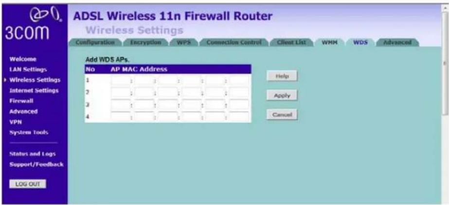
On the add WDS screen, enter the MAC address of the access point, up to 4 APs can be added to the AP MAC Address table, and click Apply.
Here is an example of how to setup two units of 3Com Router over WDS. Note that when setting up two units of 3Com Router, you should disable the DHCP function on one of the units.
Setting of the first Router:
■Set the LAN IP setting, make sure the DHCP function is enabled on this Router.
■Set the wireless settings, including SSID, channel, and wireless mode.
■ Set the wireless security setting, and enable wireless WDS function.
Setting of the second Router:
■ Set the LAN IP setting, use a different IP address from the IP address of the first Router. Disable the DHCP function, this would allow the first Router to allocate IP address for wireless clients.
■Set the wireless channel, and security same as the first Router, but use a different SSID. Make sure that WDS function is enabled.
Access the Web UI of the first Router, use wireless WDS settings screen, make sure that WDS is enabled. Click Rescan Wireless Networking to scan the available APs in your area, you should see the SSID of the second Router. Check and add the second Router to the WDS table (see Figure 56).
Figure 56 First Router Add WDS Screen
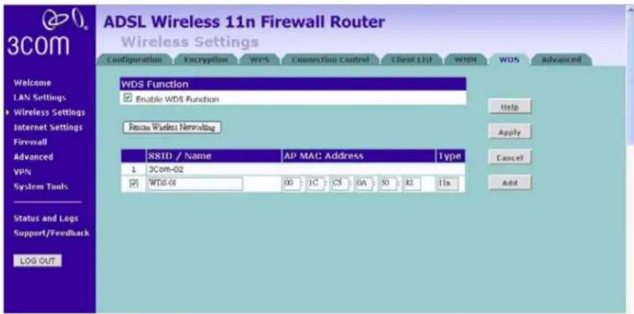
Access the Web UI of the second Router, repeat the above steps to add the first Router to the WDS table (see Figure 57).
Figure 57 Second Router Add WDS Screen
Advanced The Advanced screen allows you to configure detailed settings for your wireless connection. Please note that you should not change this settings unless you are an expert user. There are six parameters that you can configure:
Figure 58 Wireless Advanced Setting Screen

■ Beacon Interval: this represents the amount of time between beacon transmissions.
■ DTIM Interval: A DTIM (Delivery Traffic Indication Message) is a countdown mechanism used to inform your wireless clients of the next window for listening to broadcast and multicast messages.
■ Fragmentation Threshold: this is the maximum size for directed data packets transmitted. The use of fragmentation can increase the reliability of frame transmissions. Because of sending smaller frames, collisions are much less likely to occur.
■RTS Threshold: RTS stands for Request to Send, this parameter controls what size data packet the low level RF protocol issues to an RTS packet.
■CTS Protection Mode: CTS stands for Clear to Send. CTS Protection Mode boosts the Router's ability to intercept 802.11b/ 802.11g transmissions. Conversely, CTS Protection Mode decreases performance. Leave this feature disabled unless you encounter severe communication difficulties between the Router and your wireless clients.
■ AP Isolation Mode: AP Isolation is a function to prevent wireless clients connected with the device from communicating with one another. When enabled, this creates a separate virtual network for your wireless network, each of your wireless client will be in its own virtual network and will not be able to communicate with each other. You may want to utilize this feature if you have many guests that frequently connect to your wireless network.
Internet Settings You can configure the settings for your WAN port connection.
ATM PVC This feature is used to configure the parameters for your Internet connection. The information necessary to complete these screens should be obtained from your ISP. Check with your ISP first to find out what type of connection you should choose.
Figure 59 ATM PVC Screen

You should see the first entry already contains information that's been configured using the Wizard in the initial setup. If you want to change that information or set up other connection, click Edit.
There are six options available for the connection mode:
■ Disable — To disable the Internet connection function (see page 77)
■PPPoE — PPP over Ethernet, providing routing for multiple PCs (see page 77)
■ PPPoA — PPP over ATM, providing routing for multiple PCs (see page 80)
■ Bridge Mode — RFC1483 Bridged Mode, (see page 82)
■Routing Mode over ATM — RFC1483/2684 routing mode over ATM (see page 84)
■ Dynamic/Fixed IP in 1483 Bridge Mode — Using Dynamic/fixed IP for WAN connection (see page 86)
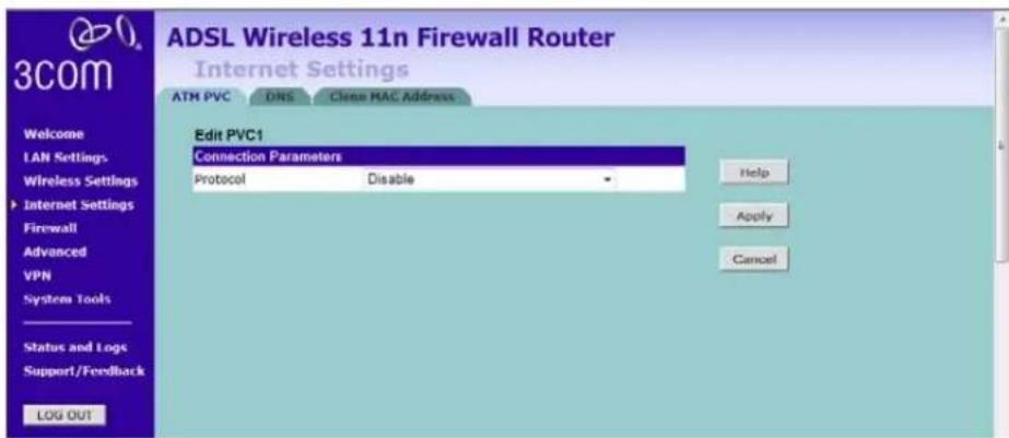
Disable
Selecting this option means that you do not want your Router to connect to the Internet.
Figure 60 Disable Internet Connection Screen
PPPoE
PPP over Ethernet, provides routing for multiple PCs, this mode is often used for the DSL connection. To configure this function correctly, you should obtain the information from your ISP.
Figure 61 PPPoE Settings Screen

1 Select PPPoE from the protocol drop-down menu.
2 Enter the IP address and Subnet mask information.
3 Enter the user name assigned to you by your ISP in the Username field. And enter the password assigned to you by your ISP in the Password field. Re-enter your password in the Confirm Password field.
4 Select always connected, auto, or manual from the Connect type drop-down menu. If you have a flat rate service charge for Internet connection, select always connected. If your ISP charges you by the minute, do not select this mode.
5 If you want your Router to automatically disconnect from the Internet after a period of inactivity, specify a time in the Idle Time field. (Enter a value of 0 to disable this timeout).
6 Enter the MTU value in the MTU field. Do not make changes to this setting, unless your ISP specifically requires a different setting other than 1454.
7 IPCP is used by PPP protocol to get one IP address from the PPP server. IPCP subnet function allows you to obtain a subnet (IP address and netmask), rather than an IP address. Check this box to enable the function.
8 IPCP Subnet Populate DHCP Server: enable this function to allow the Router to automatically apply the subnet from IPCP subnet to DHCP server. Then LAN clients can get the public IP address assigned by ISP, rather than a private IP address of the local LAN.
9 Check the Add Default Route checkbox to set this PVC as the default route, this is used when you configure more than one PVC for the Router.
10 Enter the VPI/VCI values. Or click Auto Search to find out the values. VPI (Virtual Path Identifier) and VCI (Virtual Circuit Identifier) numbers should be provided by your ISP.
11 Select the Encapsulation, VC MUX or LLC. This information should be provided by your ISP.
12 QoS Class: select CBR, UBR or VBR.
■CBR (constant bit rate): the CBR service class is intended for real-time applications, for example, those requiring tightly constrained delay and delay variation, such as voice and video applications. The consistent availability of a fixed quantity of bandwidth is considered appropriate for CBR service.
■VBR (variable bit rate): QoS class defined by the ATM Forum for ATM networks. VBR is subdivided into a real time (RT) class and non-real time (NRT) class. VBR (RT) is used for connections in which there is a fixed timing relationship between samples. VBR (NRT) is used for connections in which there is no fixed timing relationship between samples, but that still need a guaranteed QoS. Compare with ABR, CBR, and UBR.
■ UBR (unspecified bit rate): the UBR service class is intended for delay-tolerant or non-real-time applications, for example, those which do not require tightly constrained delay and delay variation, such as traditional computer communications applications. The UBR service may be considered as “best effort service”.
13 PCR/SCR/MBS: PCR (Peak Cell Rate), SCR (Sustainable Cell Rate) and MBS (Maximum Burst Size) are configurable.
14 Click Apply.
PPPoA
PPP over ATM, this is a popular choice among European DSL providers. To configure this function correctly, you should obtain the information from your ISP.
Figure 62 PPPoA Settings Screen
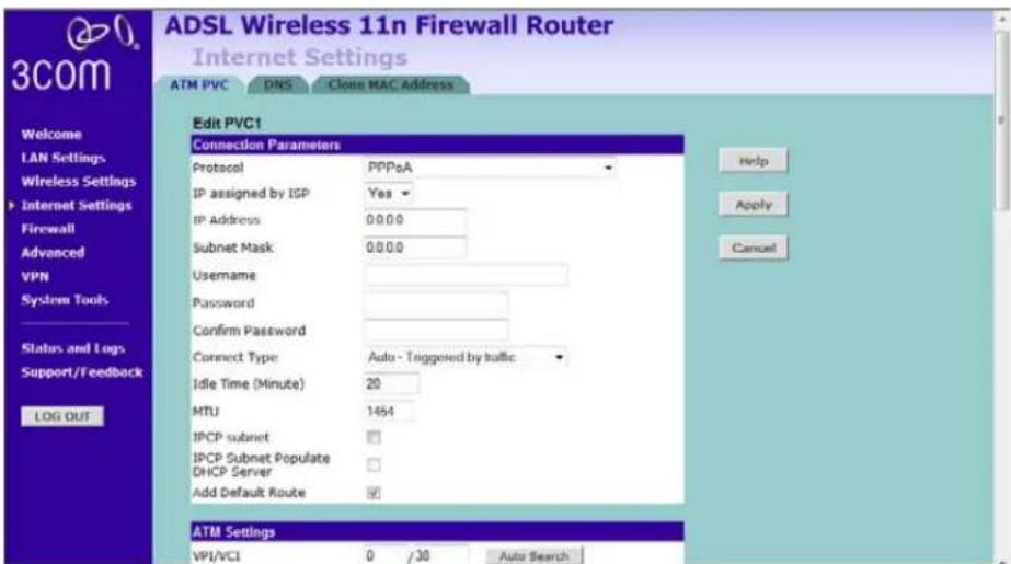
1 Select PPPoA from the protocol drop-down menu.
2 IP assigned by ISP, if select Yes, then no need to enter the IP address and Subnet mask information. If select No, then enter the IP address and Subnet mask information.
3 Enter the user name assigned to you by your ISP in the Username field. And enter the password assigned to you by your ISP in the Password field. Re-enter your password in the Confirm Password field.
4 Select always connected, auto, or manual from the Connect type drop-down menu. If you have a flat rate service charge for Internet connection, select always connected. If your ISP charges you by the minute, do not select this mode.
5 If you want your Router to automatically disconnect from the Internet after a period of inactivity, specify a time in the Idle Time field. (Enter a value of 0 to disable this timeout).
6 Enter the MTU value in the MTU field. Do not make changes to this setting, unless your ISP specifically requires a different setting other than 1454.
7 IPCP is used by PPP protocol to get one IP address from the PPP server. IPCP subnet function allows you to obtain a subnet (IP address and netmask), rather than an IP address. Check this box to enable the function.
8 IPCP Subnet Populate DHCP Server: enable this function to allow the Router to automatically apply the subnet from IPCP subnet to DHCP server. Then LAN clients can get the public IP address assigned by ISP, rather than a private IP address of the local LAN.
9 Check the Add Default Route checkbox to set this PVC as the default route, this is used when you configure more than one PVC for the Router.
10 Enter the VPI/VCI values. Or click Auto Search to find out the values. VPI (Virtual Path Identifier) and VCI (Virtual Circuit Identifier) numbers should be provided by your ISP.
11 Select the Encapsulation, VC MUX or LLC. This information should be provided by your ISP.
12 QoS Class: select CBR, UBR or VBR.
■CBR (constant bit rate): the CBR service class is intended for real-time applications, for example, those requiring tightly constrained delay and delay variation, such as voice and video applications. The consistent availability of a fixed quantity of bandwidth is considered appropriate for CBR service.
■VBR (variable bit rate): QoS class defined by the ATM Forum for ATM networks. VBR is subdivided into a real time (RT) class and non-real time (NRT) class. VBR (RT) is used for connections in which there is a fixed timing relationship between samples. VBR (NRT) is used for connections in which there is no fixed timing relationship between samples, but that still need a guaranteed QoS. Compare with ABR, CBR, and UBR.
■ UBR (unspecified bit rate): the UBR service class is intended for delay-tolerant or non-real-time applications, for example, those which do not require tightly constrained delay and delay variation, such as traditional computer communications applications. The UBR service may be considered as “best effort service”.
13 PCR/SCR/MBS: PCR (Peak Cell Rate), SCR (Sustainable Cell Rate) and MBS (Maximum Burst Size) are configurable.
14 Click Apply.
Bridge Mode
If your ISP limits access to the Internet to specific computers, this means that traffic to/from these computers only will be forwarded. In this case, Bridge Mode is used to connect to the ISP. The ISP will generally give one Internet account and limit only one computer to access the Internet. Check with your ISP to determine if this mode is used for your Internet connection.
Figure 63 Bridge Mode Screen

1 Select Bridge Mode from the Protocol drop-down menu.
2 Select VLAN.
3 Enter the VPI/VCI values. Or click Auto Search to find out the values. VPI (Virtual Path Identifier) and VCI (Virtual Circuit Identifier) numbers should be provided by your ISP.
4 Select the Encapsulation, VC MUX or LLC. This information should be provided by your ISP.
5 QoS Class: select CBR, UBR or VBR.
■CBR (constant bit rate): the CBR service class is intended for real-time applications, for example, those requiring tightly constrained delay and delay variation, such as voice and video applications. The consistent availability of a fixed quantity of bandwidth is considered appropriate for CBR service.
■VBR (variable bit rate): QoS class defined by the ATM Forum for ATM networks. VBR is subdivided into a real time (RT) class and non-real time (NRT) class. VBR (RT) is used for connections in which there is a fixed timing relationship between samples. VBR (NRT) is used for connections in which there is no fixed timing relationship between samples, but that still need a guaranteed QoS. Compare with ABR, CBR, and UBR.
■ UBR (unspecified bit rate): the UBR service class is intended for delay-tolerant or non-real-time applications, for example, those which do not require tightly constrained delay and delay variation, such as traditional computer communications applications. The UBR service may be considered as “best effort service”.
6 PCR/SCR/MBS: PCR (Peak Cell Rate), SCR (Sustainable Cell Rate) and MBS (Maximum Burst Size) are configurable.
7 Click Apply.
Routing Mode over ATM
RFC1483/2684 routed encapsulation in routing mode, it carries IP datagrams directly over ATM. DHCP client function can also be enabled to obtain an IP address dynamically.
Figure 64 Routing Mode over ATM Screen

1 Select Routing mode over ATM from the protocol drop-down menu.
2 Enter IP address, Subnet mask, and Default gateway information.
3 If your ISP provides DNS information, check the DNS Automatic from ISP box.
4 If the ISP requires you to input a Host Name, enter it in the Host Name field.
5 If your ISP uses DHCP to automatically assign IP addresses, check the DHCP Client checkbox.
6 Check the Add Default Route checkbox to set this PVC as the default route, this is used when you configure more than one PVC for the Router.
7 Enter the VPI/VCI values. Or click Auto Search to find out the values.
8 Select the Encapsulation, VC MUX or LLC. This information should be provided by your ISP.
9 QoS Class: select CBR, UBR or VBR.
■CBR (constant bit rate): the CBR service class is intended for real-time applications, for example, those requiring tightly constrained delay and delay variation, such as voice and video applications. The consistent availability of a fixed quantity of bandwidth is considered appropriate for CBR service.
■VBR (variable bit rate): QoS class defined by the ATM Forum for ATM networks. VBR is subdivided into a real time (RT) class and non-real time (NRT) class. VBR (RT) is used for connections in which there is a fixed timing relationship between samples. VBR (NRT) is used for connections in which there is no fixed timing relationship between samples, but that still need a guaranteed QoS. Compare with ABR, CBR, and UBR.
■ UBR (unspecified bit rate): the UBR service class is intended for delay-tolerant or non-real-time applications, for example, those which do not require tightly constrained delay and delay variation, such as traditional computer communications applications. The UBR service may be considered as “best effort service”.
10 PCR/SCR/MBS: PCR (Peak Cell Rate), SCR (Sustainable Cell Rate) and MBS (Maximum Burst Size) are configurable.
11 Click Apply.
Dynamic/Fixed IP in 1483 Bridge Mode
Dynamic/Fixed IP in 1483 Bridge Mode uses the same encapsulation as 1483 Bridging but with bridging function disabled. DHCP client function can also be enabled to obtain an IP address dynamically.
Figure 65 Dynamic/Fixed IP in 1483 Bridge Mode Screen

1 Select Dynamic/Fixed IP in 1483 Bridge Mode from the protocol drop-down menu.
2 Enter your IP address, subnet mask, and default gateway information.
3 IPoEoA NAT IP - enter the IP address in this field.
IPoE over AAL5 (IPoEoA) adopts a three-layer architecture, with IP encapsulation at the uppermost layer, IP over Ethernet (IPoE) in the middle, and IPoEoA at the bottom. When a device is connected to a remote access server at high speed to access an external network, PVC over ATM is used because of the long distance. In this case, it is required for the ATM port of the server to carry Ethernet packets, which is known as IPoEoA. In the application of IPoEoA, one virtual Ethernet (VE) interface can be associated with multiple PVCs. PVCs associated with the same VE interface are interconnected at layer 2.
4 If your ISP provides DNS information, check the DNS Automatic from ISP box.
5 If the ISP requires you to input a Host Name, enter it in the Host Name field.
6 If your ISP uses DHCP to automatically assign IP addresses, check the DHCP Client checkbox.
7 Check the Add Default Route checkbox to set this PVC as the default route, this is used when you configure more than one PVC for the Router.
8 Enter the VPI/VCI values. Or you can click Auto Search to automatically find out this information.
9 Select the Encapsulation, VC MUX or LLC. This information should be provided to you by your ISP.
10 QoS Class: select CBR, UBR or VBR.
■CBR (constant bit rate): the CBR service class is intended for real-time applications, for example, those requiring tightly constrained delay and delay variation, such as voice and video applications. The consistent availability of a fixed quantity of bandwidth is considered appropriate for CBR service.
■VBR (variable bit rate): QoS class defined by the ATM Forum for ATM networks. VBR is subdivided into a real time (RT) class and non-real time (NRT) class. VBR (RT) is used for connections in which there is a fixed timing relationship between samples. VBR (NRT) is used for connections in which there is no fixed timing relationship between samples, but that still need a guaranteed QoS. Compare with ABR, CBR, and UBR.
■ UBR (unspecified bit rate): the UBR service class is intended for delay-tolerant or non-real-time applications, for example, those which do not require tightly constrained delay and delay variation, such as traditional computer communications applications. The UBR service may be considered as “best effort service”.
11 PCR/SCR/MBS: PCR (Peak Cell Rate), SCR (Sustainable Cell Rate) and MBS (Maximum Burst Size) are configurable.
12 Click Apply.
DNS Domain Name Service (or Server) is an Internet service that translates domain names into IP addresses. Because domain names are alphabetic, they're easier to remember. The Internet however, is really based on IP addresses. Every time you use a domain name, a DNS service must translate the name into the corresponding IP address. For example, the domain name www.example.com might translate to 198.105.232.14.
Figure 66 DNS Screen
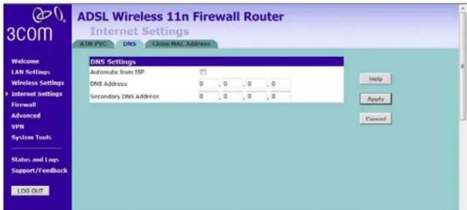
If the DNS information is automatically provided by your ISP every time you connect to it, check the Automatic from ISP checkbox (this is the default setting).
If your ISP provided you with specific DNS addresses to use, enter them into the appropriate fields on the screen and click Apply.
Many ISPs do not require you to enter this information into the Router. If you are using a static IP connection type, you may need to enter a specific DNS address and secondary DNS address for your connection to work properly. If your connection type is dynamic or PPPoE, it is likely that you do not have to enter a DNS address.
Clone MAC address To configure the hostname and Clone MAC Address information for your Router, select Internet Settings, then go to the Clone MAC address tab. The Hostname and MAC Address screen displays.
Figure 67 Hostname and Clone MAC Address Screen
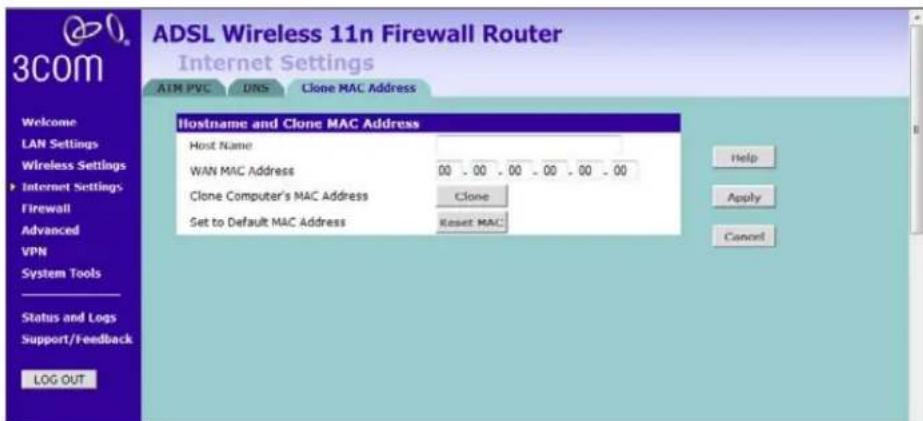
1 Some ISPs require a host name. If your ISP has this requirement, enter the host name in the Host Name field.
2 Three different ways to configure the WAN MAC Address:
■If your ISP requires an assigned MAC address, enter the values in the WAN MAC address field.
or
■If the computer that you are using is the one that was previously connected directly to the cable modem, click Clone.
or
■ To reset the MAC Address to the default, click Reset MAC.
3 Click Apply to save the settings.
Firewall
This section is for configuration settings of the Router's firewall function.
Your Router is equipped with a firewall that will protect your network from a wide array of common hacker attacks including Ping of Death (PoD) and Denial of Service (DoS) attacks. You can turn the firewall function off if needed. Turning off the firewall protection will not leave your network completely vulnerable to hacker attacks, but 3Com recommends that you leave the firewall enabled whenever possible.
SPI Stateful Packet Inspection (SPI) - The Intrusion Detection Feature of the Router limits access for incoming traffic at the WAN port.
This feature is called a "stateful" packet inspection, because it examines the contents of the packet to determine the state of the communications; i.e., it ensures that the stated destination computer has previously requested the current communication. This is a way of ensuring that all communications are initiated by the recipient computer and are taking place only with sources that are known and trusted from previous interactions. In addition to being more rigorous in their inspection of packets, stateful inspection firewalls also close off ports until connection to the specific port is requested.
Figure 68 Firewall Screen

To enable the firewall function:
1 Select the level of protection (High, Medium, or Low) that you desire from the Firewall level drop-down menu.
2 Click Apply.
■ For low and medium levels of firewall protection, refer to Figure 69. For low level of firewall protection, the DoS and SPI functions are both off. For medium level of firewall protection, DoS is on, but SPI is off.
■ For high level of firewall protection, refer to Figure 70. Both DoS and SPI are on for this level of firewall protection. The higher the firewall level is, the safer that your network is.
Figure 69 Low and Medium Level Firewall Protection Screen
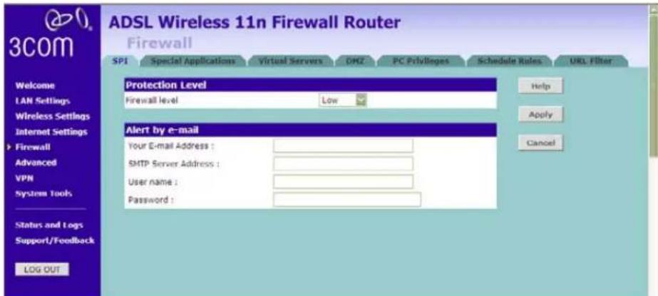
When abnormal network activity occurs, an alerting email will be sent out to you. Enter the following information to receive the email:
■Your E-mail Address
■SMTP Server Address
■User name
■Password
Figure 70 High Level Firewall Protection Screen

If you select high level of protection, you would have an option to configure additional parameters for the firewall.
■Fragmentation half-open wait - Configures the number of seconds that a packet state structure remains active. When the timeout value expires, the Router drops the un-assembled packet, freeing that structure for use by another packet.
■ TCP SYN wait - Defines how long the software will wait for a TCP session to synchronize before dropping the session.
■ TCP FIN wait - Specifies how long a TCP session will be maintained after the firewall detects a FIN packet.
■ TCP connection idle timeout - The length of time for which a TCP session will be managed if there is no activity.
■UDP session idle timeout - The length of time for which a UDP session will be managed if there is no activity.
■H.323 data channel idle timeout - The length of time for which an H.323 session will be managed if there is no activity.
■ Total incomplete TCP/UDP sessions HIGH - Defines the rate of new unestablished sessions that will cause the software to start deleting half-open sessions.
■ Total incomplete TCP/UDP sessions LOW - Defines the rate of new unestablished sessions that will cause the software to stop deleting half-open sessions.
■ Incomplete TCP/UDP sessions (per min) HIGH - Maximum number of allowed incomplete TCP/UDP sessions per minute.
■ Incomplete TCP/UDP sessions (per min) LOW - Minimum number of allowed incomplete TCP/UDP sessions per minute.
■ Maximum incomplete TCP/UDP sessions number from same host - Maximum number of incomplete TCP/UDP sessions from the same host.
■ Incomplete TCP/UDP sessions detect sensitive time period - Length of time before an incomplete TCP/UDP session is detected as incomplete
■ Maximum half-open fragmentation packet number from same host - Maximum number of half-open fragmentation packets from the same host.
■ Half-open fragmentation detect sensitive time period - Length of time before a half-open fragmentation session is detected as half-open.
■Flooding cracker block time - Length of time from detecting a flood attack to blocking the attack.
Special Applications
Special Applications (port triggering) let you choose specific ports to be open for specific applications to work properly with the Network Address Translation (NAT) feature of the Router.
Figure 71 Special Applications Screen

A list of popular applications has been included to choose from. Select the application from the Popular Applications drop-down menu. Then select the row that you want to copy the settings to from the Copy To drop-down menu, and click Copy To. The settings will be transferred to the row that you specified. Click Apply to save the setting for that application.
If your application is not listed, you will need to check with the application vendor to determine which ports need to be configured. You can manually enter the port information into the Router. To manually enter the port information:
1 Specify the trigger port (the one used by the application when it is initialized) in the Trigger Port column, and specify whether the trigger is TCP or UDP.
2 Specify the Public Ports used by the application, that will need to be opened up in the firewall for the application to work properly. Also specify whether these ports are TCP or UDP. Note that the range of the trigger port is from 1 to 65535. You can enter the port number as one single port, or in range, use comma to separate different entries.
3 Check the Enabled checkbox, then click Apply.
Virtual Servers
The Virtual servers feature allows you to route external (Internet) calls for services such as a web server (port 80), FTP server (Port 21), or other applications through your Router to your internal network. Since your internal computers are protected by a firewall, machines from the Internet cannot get to them because they cannot be 'seen'.
If you need to configure the Virtual Server function for a specific application, you will need to contact the application vendor to find out which port settings you need.
The maximum number of virtual servers that can be configured is 20.
Figure 72 Virtual Servers Screen

A list of popular servers has been included to choose from. Select the server from the Popular servers drop-down menu. Then click Add, your selection will be added to the table.
If the server that you want to use is not listed in the drop-down menu, you can manually add the virtual server to the table. To manually configure your virtual servers:
1 Enter the IP address, and the description in the spaces provided for the internal machine.
2 Select the protocol type (TCP, UDP, or both TCP and UDP) from the drop-down menu.
3 Specify the public port that will be seen by clients on the Internet, and the LAN port which the traffic will be routed to.
4 You can enable or disable each Virtual Server entry by checking or unchecking the appropriate Enabled checkbox.
5 Click Apply to save the changes for each Virtual Server entry.
DMZ If you have a client PC that cannot run an Internet application properly from behind the firewall, you can open the client up to unrestricted two-way Internet access. This may be necessary if the NAT feature is causing problems with an application such as a game or video conferencing application.
Figure 73 DMZ Screen


Use this feature on a temporary basis. The computer in the DMZ is not protected from hacker attacks.
Check the Enable DMZ box, the IP Address of Virtual DMZ Host will appear.
1 Enter the last digits of the LAN IP address in the Client PC IP Address field. Enter the IP address (if known) that will be accessing the DMZ PC into the Public IP Address field, so that only the computer on the Internet at this address can access the DMZ PC without firewall protection. If the IP
address is not known, or if more than one PC on the Internet will need to access the DMZ PC, then set the Public IP Address to 0.0.0.0.
In the default setting, (line 1) refer to Figure 73, Public IP address is set to 0.0.0.0 and it is automatically transformed by default WAN IP. We only allow one DMZ server to be accessed by public IPs (Many to 1 NAT). If you have more than one DMZ server, you have to set a second WAN IP in line 2 and define which IP address of DMZ server you would like to set in the Client PC IP address. For this Router, only 1 to 1 NAT function is allowed.
2 Click Apply.
PC Privileges
The Router can be configured to restrict access to the Internet, email or other network services at specific days and times. Restriction can be set for a single computer, a range of computers, or multiple computers.
You can define the traffic type permitted or not-permitted to the Internet. Note that this function requires time-scheduling to be applied to access control, you will need to create schedule rules first and then use PC Privileges.
Figure 74 PC Privileges Screen

1 Select one option from filtering function:
■ All PCs have access to the Internet: selecting this mode means that all clients have full access to Internet.
■PCs access authorised services only: selecting this mode means clients can only access authorised or limited services.
2 Click Add PC (refer to Figure 75).
To edit or delete specific existing filtering rules, click on Edit or Delete for the appropriate filtering rule.
Figure 75 PC Privileges Add PC Screen

1 Enter a description in the Client PC Description field, and the IP address or IP address range into the Client PC IP Address fields.
2 To bypass the URL Filter, check the corresponding Bypass checkbox. If you check this option, then the Web sites and keywords defined in this screen will not be filtered out.
3 Select the services to be blocked. A list of popular services is listed on this screen, to block a particular service, check the appropriate Blocking checkbox.
If the service to be restricted is not listed here, you can enter a custom range of ports at the bottom of the screen, under User Defined Blocked Ports.
4 If you want the restriction to apply only at certain times, select the schedule rule to apply from the Schedule Rule drop-down menu.
Note that schedule rules are defined on the Schedule Rules screen (see page 99).
5 Click Apply to add the settings.
Schedule Rule
The Router can be configured to restrict access to the Internet, email or other network services at specific days and times. Define the time in this screen, and define the rules in the PC Privileges screen (see page 97).
Figure 76 Schedule Rule Screen

1 Click Add Rule to add a schedule rule (refer to Figure 77).
Figure 77 Add Schedule Rule Screen
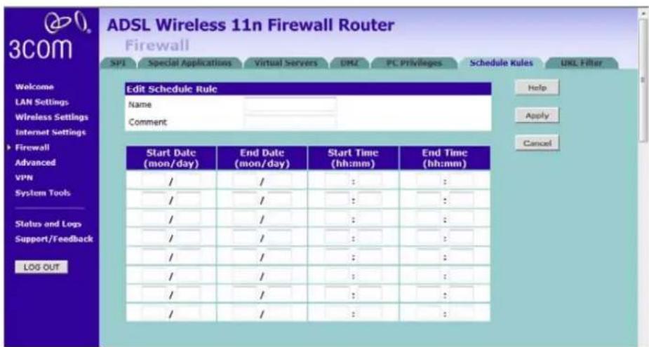
2 Enter a name and comment for the schedule rule in the Name and Comment fields.
3 Specify the schedule rules for the required days and times - note that all times should be in 24 hour format.
4 Click Apply.
URL Filter
To configure the URL filter feature, use the table on the URL Filter screen to specify the Web sites (www.somesite.com) and/or keywords you want to filter on your network.
For example, entering a keyword of xxx would block/allow access to any URL that contains the string xxx.
Figure 78 URL Filter Screen

1 Check the Enable URL Filtering Function checkbox. The rule table will appear.
2 Enter the URL address or keywords in the URL/Keyword field.
3 Select Denied or Allowed from the Mode drop-down menu.
To complete this configuration, you will need to create or modify the filtering rule in the PC Privileges screen (see page 97).
From the PC Privileges Add PC screen (Figure 75), if you check the option: Bypass URL Filter, then the Web sites and keywords defined in this screen will not be filtered out.
Advanced
The Advanced section allows you to set additional parameter details for the Router. You can configure:
■Security
■VLAN
■Static Routes
■RIP
■DDNS
SNMP
■Syslog
■Proxy Arp
■QoS Settings
Security
Use the Security screen to set the advanced security settings for the Router.
Figure 79 Security Screen

■ NAT — (Network Address Translation), NAT is the method by which the Router shares the single IP address assigned by your ISP with the computers on your network.
This function should only be disabled by advanced users, and if your ISP assigns you multiple IP addresses or you need NAT disabled for an advanced system configuration. If you have a single IP address and you turn NAT off, the computers on your network will not be able to access the Internet. Other problems may also occur.
■ IPSec NAT-T Pass-through — NAT-T (NAT Traversal) is an Internet Draft proposed to IETF in order to help the problems associated with passing IPsec traffic through NAT Routers. For NAT-T to work, both ends of the connection need to support this function. Ensure that you select NAT-T only if it is needed as it will reduce LAN-WAN throughput. This Router supports NAT-T draft 2 implementation.
■ Universal Plug and Play — This is a technology that offers seamless operation of voice messaging, video messaging, games, and other applications that are Universal Plug and Play compliant. Some applications require the Router's firewall to be configured in a specific way to operate properly. This usually requires opening TCP and UDP ports and in some instances setting trigger ports. An application that is Universal Plug and Play compliant has the ability to communicate with the Router, basically "telling" the Router which way it needs the firewall configured. The Router ships with the Universal Plug and Play feature disabled. If you are using any applications that are Universal Plug and Play compliant, and want to take advantage of the Universal Plug and Play features, you can enable this feature. Simply check the Enable Universal Plug and Play checkbox. Click Apply to save the change.
■WAN Ping Blocking — Computer hackers use what is known as "Pinging" to find potential victims on the Internet. By pinging a specific IP address and receiving a response from the IP address, a hacker can determine that something of interest might be there. The Router can be set up so it will not respond to an Internet Control Message Protocol (ICMP) Ping from the outside. This heightens the level of security of your Router. To turn off the ping response, check Block ICMP Ping and click Apply; the Router will not respond to an ICMP ping from the Internet.
■MSS Clamping — You might not be able to browse some Web sites or to send email messages that contain attachments from an Internet Connection Sharing client computer if your outbound connection is through a Windows XP-based Internet Connection Sharing host computer that uses Point-to-Point Protocol over Ethernet (PPPoE). This issue may occur if the Windows XP-based Internet Connection Sharing host computer uses a smaller Maximum Transmission Unit (MTU) size on the WAN interface (the PPPoE connection to the Internet) than it uses on the private interface (the Ethernet connection to the Internet Connection Sharing client). If a packet is larger than the MTU size on the WAN interface, the client sends an Internet Control Message Protocol (ICMP) error to the external server to request that the server negotiate the TCP Maximum Segment Size (MSS). However, this message may be blocked by some firewalls. When this occurs, the packet is dropped. To allow the message to go through the firewall, enable MSS Clamping. MSS clamping will make Internet Connection Sharing set the MSS value low enough to match the external interface.
- Remote Administration — This feature allows you to make changes to your Router’s settings from anywhere on the Internet. Four options are available:
■ If you do not want to use this feature, select Disable Remote Administration.
- Select Enable administration from a single Internet Host, and enter the IP address, to allow only one computer to use the remote administration. This is more secure, as only the specified IP address will be able to manage the Router.
- Select Enable administration from a whole Subnet Internet Host, and enter the IP address and subnet mask, to allow PCs from that specific subnet group to use the remote administration.
■ Select Enable administration from any Internet Host, this allows any computer to access the Router remotely.

Before you enable this function, ensure that you have changed the factory default Administration Password.
VLAN
A VLAN is a flexible group of devices that can be located anywhere in a network, but they communicate as if they are on the same physical segment. With VLANs, you can segment your network without being restricted by physical connections - a drawback of traditional network design. As an example, with VLANs you can segment your network according to:
■ Departmental groups - For example, you can have one VLAN for the Marketing department, another for the Finance department, and another for the Development department.
■Hierarchical groups - For example, you can have one VLAN for directors, another for managers, and another for general staff.
■Usage groups - For example, you can have one VLAN for users of e-mail, and another for users of multimedia.
The main benefit of VLANs is that they provide a network segmentation system that is far more flexible than any traditional network. Using VLANs also provides you with three other benefits:
■It eases the change and movement of devices on IP networks: With traditional IP networks, network administrators spend much of their time dealing with moves and changes. If users move to a different IP subnet, the IP addresses of each end-station must be updated manually.
With a VLAN setup, if an end-station in VLAN 1 is moved to a port in another part of the network, you only need to specify that the new port forwards VLAN 1 traffic.
- It provides extra security: Devices within each VLAN can only communicate directly with devices in the same VLAN. If a device in VLAN 1 needs to communicate with devices in VLAN 2, the traffic needs to pass through a routing device or Layer 3 switch.
■It helps to control broadcast traffic: With traditional networks, congestion can be caused by broadcast traffic that is directed to all network devices whether they require it or not. VLANs increase the efficiency of your network because each VLAN can be set up to contain only those devices that need to communicate with each other.
The VLAN screen allows you to setup VLAN groups. Note that Wireless LAN is permanently assigned to Default VLAN.
Figure 80 VLAN Screen

Click Add VLAN to create a new entry (see Figure 81).
Figure 81 VLAN Profile Screen

■Enter a description for your VLAN in the Description field.
■ Enter the IP Address and subnet mask in the corresponding fields.
■Select to set the NAT Domain as public or private.
■ IGMP Snooping: enabling it will turn on the feature that allows an Ethernet switch to "listen in" on the IGMP conversation between hosts and routers.
■IGMP Querier: enabling this function will send out periodic IGMP queries.
Click Apply.
Static Routes
You can configure static routes in this screen. You can setup a static route that will get all traffic with destination to business network to go through VPN tunnel and the rest outside of the VPN tunnel.
Figure 82 Static Routes Screen

To add a static route entry to the table, click Add (see Figure 83).
To change an existing entry, click Edit. To delete an entry, click Delete.
Figure 83 Add Static Route Screen

Enter the following information:
■ Network Address — the network address of the static route.
■Subnet Mask — the subnet mask of the route.
A network address of 0.0.0.0 and a subnet mask of 0.0.0.0 indicates the default route.

■ Gateway — the Router used to route data to the network specified by the network address.
■Interface — select the interface.
Note that you should only configure either the Gateway information or select the Interface. After you have finished making changes to the table, click Apply.
Here is an example of setting up a static route.
■IP address of your PC: 10.1.4.52
■Subnet mask: 255.255.252.0
■Default Gateway: 10.1.4.254
■Network Address: 10.1.4.0
Figure 84 Add Static Route Example Screen

RIP RIP (Routing Information Protocol) - RIP allows the network administrator to set up routing information on one RIP-enabled device (this Router), and send that information to all RIP-enabled devices on the network.
Figure 85 RIP Parameter Screen
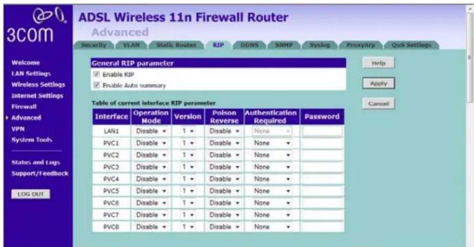
You can set up RIP independently on both LAN and WAN interfaces.
1 Check the Enable RIP checkbox.
2 Check the Enable Auto summary checkbox. Auto summarization sends simplified routing data to other RIP-enabled devices rather than full routing data.
3 Select the Operation Mode:
■ Disable — RIP is not enabled for the WAN or LAN interface.
■ Enable — RIP is enabled for the WAN or LAN interface. The router will transmit RIP update information to other RIP-enabled devices.
■ Silent — RIP is enabled, however the Router only receives RIP update messages, it will not transmit any messages itself.
4 In the Version field, select 1 or 2.

3Com recommends that you only use RIPv1 if there is an existing RIP-enabled device on your network that does not support RIPv2. In all other cases, you should use RIPv2.
5 Use the Poison Reverse drop-down menu to enable or disable Poison Reverse on the Router. Enabling Poison Reverse on your Router allows it to indicate to other RIP-enabled devices that they have both routes that point to each other, preventing data loops.
6 Use the Authentication Required field to choose the mode of authentication:
■ None — Switches off authentication on the specified interface.
■ Password — An unencrypted text password that needs to be set on all RIP-enabled devices connected to this Router. RIP information is not shared between devices whose passwords do not match.
7 In the Password field, enter the required password.
8 Click Apply.
DDNS The Router provides a list of dynamic DNS providers for you to choose from. Dynamic Domain Name Server (DDNS) enables you to map a static domain name to a dynamic IP address. This function allows you to create a hostname that points to your dynamic IP or static IP address or URL.
Before you set up DDNS, you must obtain an account, password or key and static domain name from your DDNS provider. The Router supports five DDNS providers:
■DynDNS.org
■TZO.com
■Dt DNS.com
■No-IP.com
■Zoneedit.com
Figure 86 Dynamic Domain Name Server (DDNS) Screen
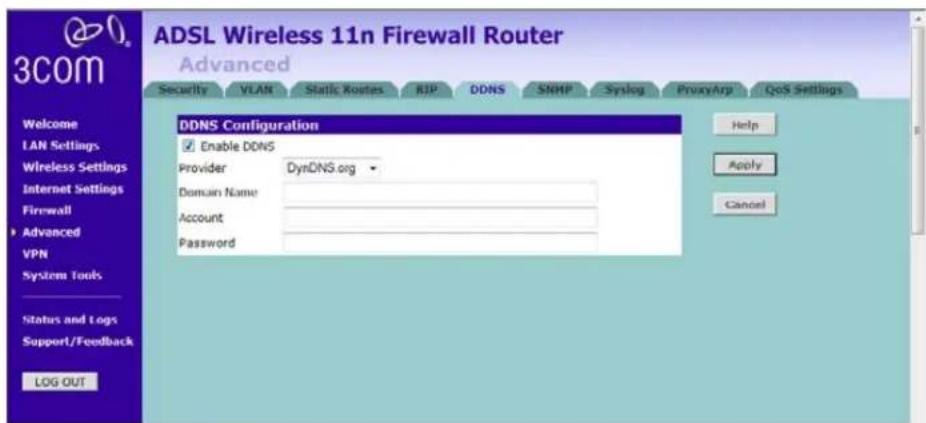
1 Check Enable DDNS.
2 Select the provider, and then enter the necessary information provided by your DDNS provider.
3 Click Apply.
SNMP SNMP (Simple Network Management Protocol) allows remote management of your Router by a PC that has an SNMP management agent installed.
Check the Enable SNMP box, the table will appear.
Figure 87 SNMP Screen

Enter the System Contact, System Name, and System Location information.
To Configure SNMP Community:
1 In the Community column, enter the name of the SNMP communication channel. Your SNMP management agent needs to be configured with this name so that it can communicate with your Router.
2 In the Access column, select Read to allow the management agent to collect data (for example, bandwidth usage) from your Router. Select Write to allow the management agent to change the configuration of your Router.
3 Check the appropriate Valid checkbox to enable the communication channel.
You can configure the Router to send status messages to the SNMP management agent if a problem occurs on the network. To configure SNMP traps:
1 In the IP Address field, enter the IP address of the PC to which you want your Router to send status messages.
2 In the Community field, enter the name of the SNMP communication channel to which you want your Router to send status messages.
3 Set the Version field to match the version of trap messaging that your SNMP management agent supports. The Router supports V1 and V2c trap messaging.
Syslog Using third party syslog software, this Syslog Server tool will automatically download the Router log to the specified server IP address.
Figure 88 Syslog Server Screen
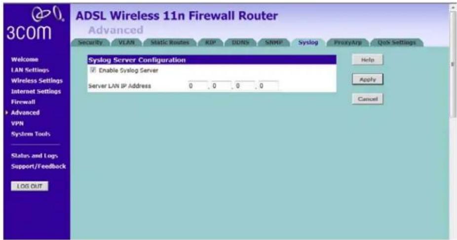
1 Check the Enable Syslog Server checkbox.
2 Enter the Server LAN IP Address in the space provided.
3 Click Apply.
Proxy ARP Proxy ARP is the technique in which one host, usually a Router, answers ARP requests intended for another machine. By “faking” its identity, the Router accepts responsibility for routing packets to the “real” or intended destination. This heightens the security for your network.
Figure 89 Proxy ARP Screen
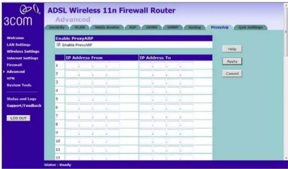
1 Check the Enable ProxyARP box.
2 Enter the corresponding IP address in the IP Address From and IP Address To fields.
3 Click Apply.
QoS Settings The QoS (Quality of Service) function allows you to differentiate your network traffic and provide it with high-priority forwarding service.
The bandwidth gap between LAN and WAN may significantly degrade the performance of critical network applications, such as VoIP, gaming, and VPN. This QoS function allows you to classify traffic of applications and provides them with differentiated services (Diffserv).
Figure 90 QoS Settings Screen
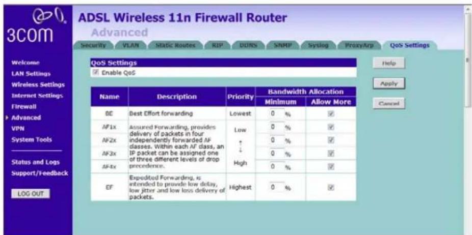
1 Check the Enable QoS box, and enter the value for WAN Out Bandwidth.
2 Define the minimum percentage of bandwidth for each type of traffic.
3 Check the corresponding box to allow more bandwidth allocation.
4 Click Apply.
Note that once QoS is enabled, a new tab, Traffic mapping, will become visible, see Figure 91.
Traffic Mapping
Up to 16 rules can be defined to classify your network traffic into Diffserv forwarding groups and outgoing connections.
Figure 91 Traffic Mapping Screen

Click Add, the Edit Traffic Class screen will appear.
Figure 92 Edit Traffic Class Screen

1 Define the Rule name.
2 Select the traffic type from drop-down menu.
3 Select the forwarding group from the Map to Forwarding Group drop-down menu.
4 Select the value from the Remark DSCP as drop-down menu.
5 Click the ADVANCED CONFIG button, a more detailed Edit Traffic class screen will appear, see Figure 93.
Figure 93 Detailed Edit Traffic Class Screen
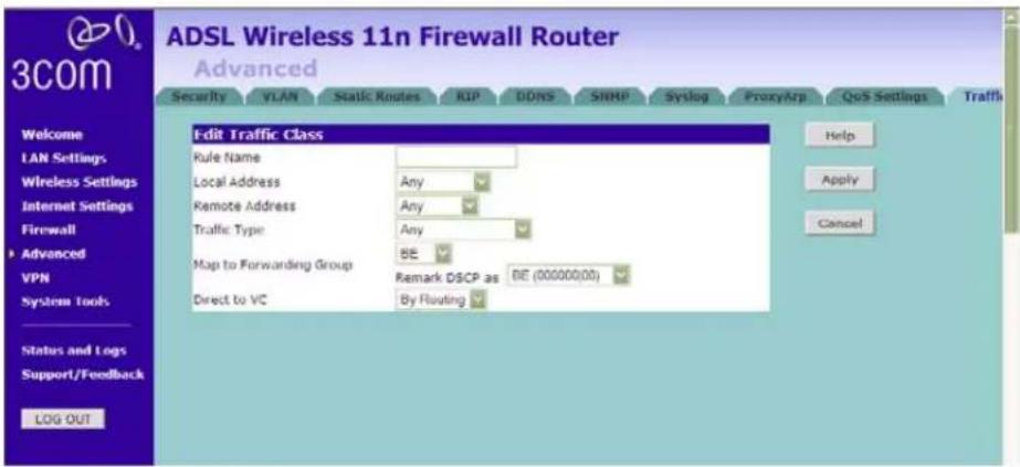
Enter the information, then click Apply to make the settings to take effect.
VPN The Router has a Virtual Private Network (VPN) feature that provides a
secure link between remote users and the corporate network by establishing an authenticated and encrypted tunnel for passing secure data over the Internet. The Router supports three modes of VPN operation:
■ IPSec (IP Security) — provides IP network-layer encryption. IPSec can support large encryption networks (such as the Internet) by using digital certificates for device authentication. When setting up an IPSec connection between two devices, make sure that they support the same encryption method.
Note: Enabling IPSec VPN disables pass-through to IPSec and L2TP over IPSec Virtual Servers on the LAN. Pass-through outbound from clients on the LAN to servers on the Internet is unaffected.
■ PPTP (Point-to-Point Tunneling Protocol) — provides a secure tunnel for remote client access to a PPTP security gateway. It is not as secure as IPSec but is easy to administer. PPTP does not support gateway to gateway connections and is only suitable for connecting remote users. Check that your ISP's routers support this protocol before you use it.
Note: Enabling the PPTP Server disables PPTP pass-through to a Virtual Server on the LAN. Pass-through outbound from clients on the LAN to servers on the Internet is unaffected.
■ L2TP over IPSec — this is a combination of two protocols. L2TP is used to authenticate a user, and IPSec is used to encrypt data. L2TP over IPSec does not support gateway to gateway connections and is only suitable for connecting remote users. Check that your ISP's routers support this protocol before you use it.
Note: Enabling L2TP over IPSec disables pass-through to IPSec and L2TP over IPSec Virtual Servers on the LAN. Pass-through outbound from clients on the LAN to servers on the Internet is unaffected.
Using the VPN Tunnel Configuration screen, you can add new IPSec, L2TP over IPSec and PPTP connections, and to edit existing connections. When adding or editing values on this screen remember that both ends of the connection must contain the same information.
Figure 94 VPN Screen

1 Check the Enable IPSec box, configuration details screen appears.
Figure 95 Enable IPSec Screen

2 Enter the Local ID Name of your VPN. (the default is 3ComVPN)
3 Click Add to create a new entry, see Figure 96.
Figure 96 Add New VPN Tunnel Configuration Screen

On the VPN Tunnel Parameter screen,
1 Set the VPN Tunnel Type to IPSec.
2 Enter a descriptive name for the tunnel in the Tunnel Name field.
3 Remote VPN Gateway - select IP address, and then enter the IP address in the IP Address/Host Name field. If you select ANY, then it would be no need to enter the IP address, as any remote server can be used.
4 At the Remote Party ID drop-down list, select either IP_IPV4_ADDR or ID_USER_FQDN. This information must be entered identically on the IPSec software installed on the client's machine.
If IP_IPV4_ADDR is selected, then enter the IP address and subnet mask in the Remote Network Address, and Remote Subnet Mask fields. The remote network address is usually the network address of the LAN connected to the remote server.
If ID_USER_FQDN is selected, then enter the name for the Remote Party ID in the text box area next to the drop-down menu. This name must be unique for each connection rule that you create. Enter the IP address and subnet mask in the Remote Network Address, and Remote Subnet Mask fields.
Note that if you select IKE Main Mode from the Key Management drop-down menu (see step 6), you must enter IP_IPV4_ADDR here.
5 Select the Local Party ID, and then enter the ID, Network Address and Subnet Mask of the Local Secure Group. The network address of the local secure group is usually the network address of the local network.
6 From the Key Management drop-down menu, select either IKE Main Mode or IKE Aggressive Mode.
7 SA (Security Association) attribute - select the option to use for SA attribute.
8 In the Pre-shared Key field, enter the password for the connection. This must be unique for each connection rule that you create.
9 Select MD5, or SHA1 from the Authentication Algorithm drop-down menu. Both ends of the connection must use the same value.
10 Select DES, 3DES, Null, AES-128, AES-192, or AES-256 from the Encrypt Algorithm drop-down menu. Both ends of the connection must use the same value.
11 Enter the Key lifetime, in seconds. The default is 3600 seconds. The value must be at least 300 seconds.
12 PFS - Perfect Forward Secrecy, check this box, then the Diffie-Hellman Group options become available. The use of PFS is optional, enabling PFS will add another layer of encryption security.
13 Diffie-Hellman Group - select the group to use for Diffie-Hellman key exchange.
14 Check the IKE Keep Alive box to enable this function. The time value is the number of seconds that the router waits between sending IKE keepalive packets.
15 Click Apply.
Check the Enable L2TP box, configuration details screen appears, see Figure 97.
Figure 97 Enable L2TP Screen

1 Enter the Pre-shared Key for L2TP Server over IPSec Setting.
2 Define the IP Address Pool for L2TP clients, enter the start/end address.
3 Click Add to create a new entry, see Figure 98.
Figure 98 Add New VPN Tunnel Parameter L2TP over IPSec Screen

1 Set the Tunnel Type to L2TP over IPSec.
2 Enter a descriptive name for the tunnel in the Tunnel Name field.
3 Enter the User name and Password.
4 Enter the Idle Timeout value.
5 Set the L2TP Type Setting to L2TP Server, or L2TP Client.
■if you set the type as L2TP Client, then set the Local Type Setting to Network or Host, then enter the Remote Server IP. Check the Auto reconnect box, if you want to auto-reconnect after disconnection.
■ if the L2TP Type Setting is set to L2TP Server, go to step 6.
6 Check the box to enable the Remote Network Setting, and then enter the Remote Network Address, and Remote Subnet Mask information.
7 When the L2TP Type Setting is set to L2TP Client, you would then need to enter the Pre-shared Key information.
8 Click Apply.
Check the Enable PPTP box, configuration details screen appears, see Figure 99.
Figure 99 Enable PPTP Screen

1 Define the IP Address Pool for PPTP clients, enter the start/end address.
2 Click Add to create a new entry, see Figure 100.
Figure 100 Add new PPTP VPN Tunnel Screen

1 Set the Tunnel Type to PPTP.
2 Enter a descriptive name for the tunnel in the Tunnel Name field.
3 Enter the User name and Password.
4 Enter the Idle Timeout value.
5 Set the PPTP Type Setting to PPTP Server, or PPTP Client.
■ if you set the type as PPTP Client, then set the Local Type Setting to Network or Host, then enter the Remote Server IP. Check the Auto reconnect box, if you want to auto-reconnect after disconnection.
■ if the PPTP Type Setting is set to PPTP Server, go to step 6.
6 Check the box to enable the Remote Network Setting, and then enter the Remote Network Address, and Remote Subnet Mask information.
7 When the PPTP Type Setting is set to PPTP Client, you would then need to enter the Pre-shared Key information.
8 Click Apply.
System Tools These screens allow you to manage different parameters of the Router and perform certain administrative functions.
Restart Router Sometimes it may be necessary to restart (or reboot) the Router. Restarting the Router from this screen will not delete any of your configuration settings.
Click the Restart the Router button to restart the Router.
Figure 101 Restart Router Screen
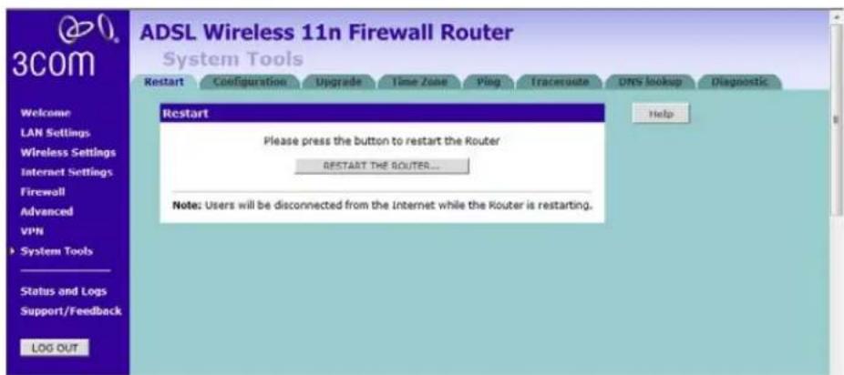
Configuration Use this configuration screen to backup, restore or reset the configuration details of the Router.
Figure 102 Configuration Screen

■ Backup Configuration — You can save your current configuration by clicking the Backup button. Saving your configuration will allow you to restore it later if your settings are lost or changed. It is recommended that you backup your current configuration before performing a firmware update.
■ Restore Configuration Data — The Restore Settings option will allow you to restore a previously saved configuration. Please select the configuration file using the Browse button and click Restore.
■Reset to Factory Default — Using this option will reset all of the settings in the Router to the factory default settings. It is recommended that you backup your settings before you restore all of the defaults. To restore the factory default settings, click Reset. Note that all of your current configuration will be lost.
Upgrade From time to time 3Com may release new versions of the Router's firmware. Firmware updates contain improvements and fixes to problems that may have existed.
Figure 103 Upgrade Screen

Please download the firmware file to your PC first, and then click Browse to locate the file, and select the firmware file. Click Upgrade to upload the firmware to the Router.
Time Zone You can set the time settings for the Router on this screen.
Figure 104 Time Zone Screen
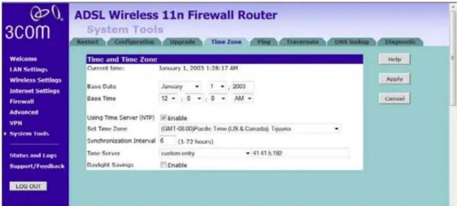
The Router keeps time by connecting to a Network Time Protocol (NTP) server. This allows the Router to synchronize the system clock to the Internet. The synchronized clock in the Router is used to record the security log and control client filtering. Select the time zone that you reside in.
If you reside in an area that observes Daylight Saving, then check the Enable Daylight Savings box. The system clock may not update immediately. Allow at least 15 minutes for the Router to contact the time servers on the Internet and get a response. You cannot set the clock yourself.
You can specify which NTP servers the Router will use to update the system clock, although doing this should only be necessary if you are experiencing difficulty.
Ping The ping tool is used to test if the network is working properly.
Figure 105 Ping Screen

1 Enter the IP address or domain name in the IP Address or Domain Name field, and click Ping.
2 Select from the Number of times to Ping drop-down menu.
3 The Router keeps a log of the ping test, click Clear Log to delete the records.
Traceroute Traceroute is the program that shows you the route over the network between two systems, listing all the intermediate routers a connection must pass through to get to its destination. It can help you determine why your connections to a given server might be poor, and can often help you figure out where exactly the problem is. It also shows you how systems are connected to each other, letting you see how your ISP connects to the Internet as well as how the target system is connected.
Figure 106 Traceroute Screen

1 Enter the IP address or domain name in the IP Address or Domain Name field, and click Traceroute.
2 The Router keeps a log of the traceroute test, click Clear Log to delete the records.
DNS Lookup DNS Lookup is the process of resolving an IP address (i.e. 192.168.11.137) to a host name (i.e. xxxcompany.net).
Figure 107 DNS Lookup Screen
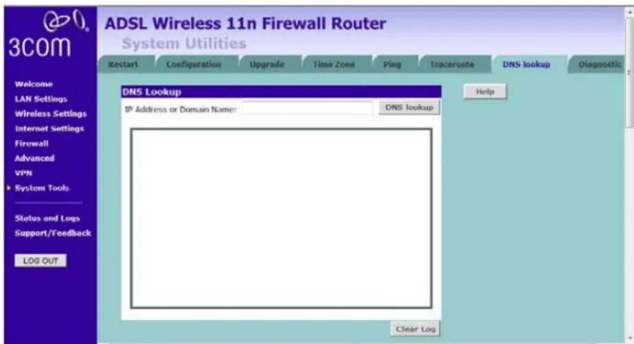
1 Enter the IP address or domain name in the IP Address or Domain Name field, and click DNS lookup.
2 The Router keeps a log of the DNS lookup test, click Clear Log to delete the records.
Diagnostic This screen is designed to collect diagnostic information of this Router, click the Start button to start the diagnostic, then save the information in a file. You can later use this information to analyze your network.
Figure 108 Diagnostic Screen
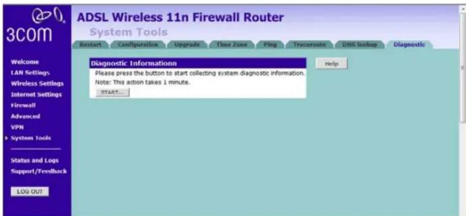
Status and Logs
You can use the Status Screen to view version numbers for your Router's software and hardware and check the status of connections to Internet, LAN and WLAN interfaces.
Status This screen shows Router status and statistics.
■Release - use this button to release the current IP.
■Renew - use this button to obtain a new IP.
Figure 109 Status Screen

ADSL Status This screen shows ADSL modem status and statistics.
Figure 110 ADSL Status Screen

ATM PVC Status This screen shows ATM PVC status and statistics.
■ Click Disconnect to disconnect from your ISP.
■ Click Connect to make a connection with your ISP.
Figure 111 ATM PVC Status Screen

Routing Table
This screen displays details for the default routing used by your Router and any routing created using Static Routing or RIP.
Figure 112 Routing Table Screen
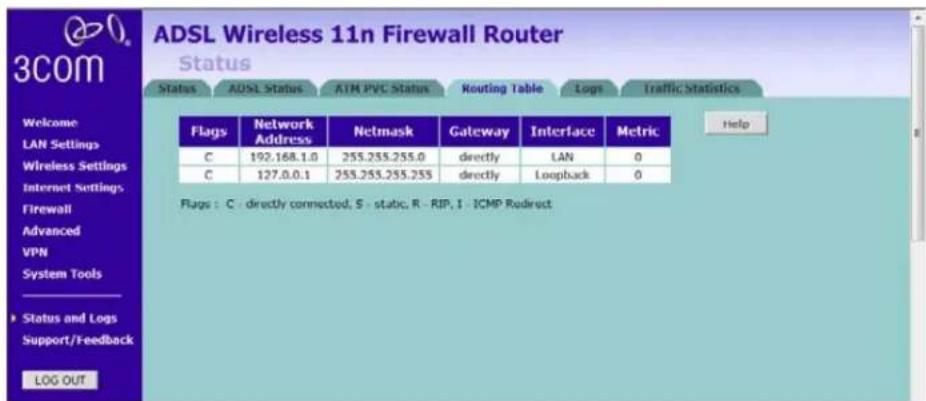
Logs This screen shows any attempts that have been made to gain access to your network as well as the system activities.
Figure 113 Logs Screen

■ Click Help to view the help file.
- Click Save to save the log to the hard disk as a text file. When prompted for a location to save the file to, specify a file name and location, and then click OK.
- Click Clear to clear the log (note that all current entries will be erased).
■Click Refresh to update the record.
Traffic Statistics
This screen shows the traffic statistics. Use the Refresh button to update the information. Note that the current implementation only shows traffic statistics per forwarding group. Hence if QoS is not enabled, this screen will always show zero values.
Figure 114 Traffic Statistics Screen
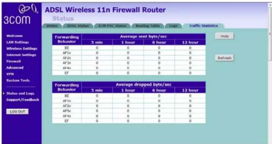
Support/Feedback
You can use the Support/Feedback screen to obtain support and help, and also provide feedback to 3Com.
Support Figure 115 Support Screen

This screen shows support information.
Feedback To provide feedback to 3Com, please click Provide Feedback, and this will connect you to the 3Com Web site.
Figure 116 Feedback Screen
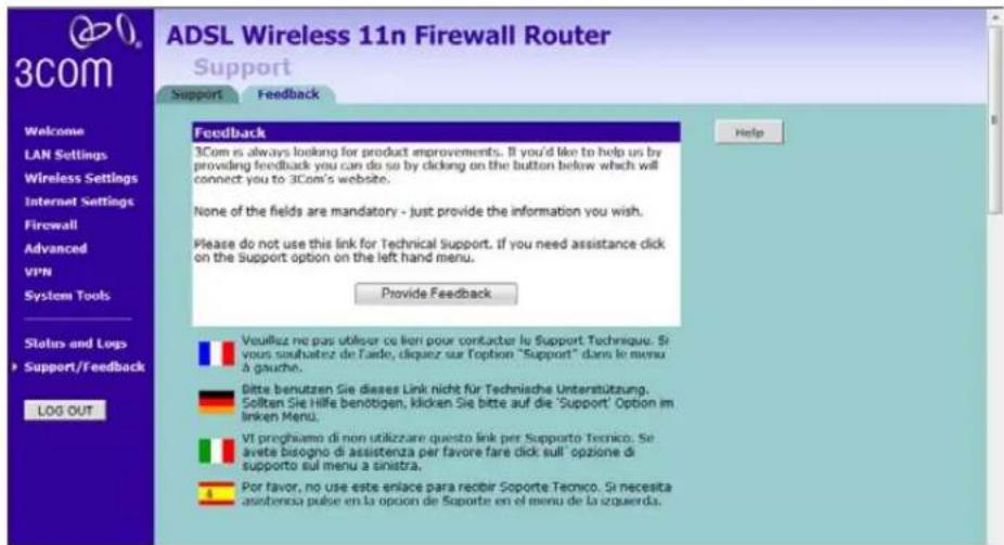
This screen shows feedback information.
6
TROUBLESHOOTING
Basic Connection Checks
The Router has been designed to aid you when detecting and solving possible problems with your network. These problems are rarely serious; the cause is usually a disconnected or damaged cable, or incorrect configuration. If this section does not solve your problem, contact your supplier for information on what to do next.
Perform these actions first:
■Ensure all network equipment is powered on.
■ Power each piece of network equipment off, wait about five seconds and then power each one on.

CAUTION: Do not power the Router off and then immediately on. Wait about five seconds between power cycles.
Check the following symptoms and solutions:
■Check that the Router is connected to your computers and to the telephone line, and that all the equipment is powered on. Check that the LAN Status and SYNC LEDs on the Router are illuminated, and that any corresponding LEDs on the NIC are also illuminated.
■ Ensure that the computers have completed their start-up procedure and are ready for use. Some network interfaces may not be correctly initialized until the start-up procedure has completed.
■ If the link status LED does not illuminate for a port that is connected, check that you do not have a faulty cable. Try a different cable.
| Browsing to the Router Configuration Screens | If you have connected your Router and computers together but cannot browse to the Router configuration screens, check the following:■Confirm that the physical connection between your computer and the Router is OK, and that the LAN Status LEDs on the Router and network adapter are illuminated. Some NICs do not have status LEDs, in which case a diagnostic program may be available that can give you this information.■Ensure that you have configured your computer as described in Chapter 3. Restart your computer while it is connected to the Router to ensure that your computer receives an IP address.■When entering the address of the Router into your web browser, ensure that you use the full URL including the http:// prefix (e.g. http://192.168.1.1).■Ensure that you do not have a Web proxy enabled on your computer. Go to the Control Panel and click on Internet Options. Select the Connections tab and click on the LAN Settings button at the bottom. Make sure that the Proxy Server option is unchecked.■ If you cannot browse to the Router, use the winipcfg utility in Windows 98/ME to verify that your computer has received the correct address information from the Router. From the Start menu, choose Run and then enter winipcfg. Check that the computer has an IP address of the form 192.168.1.xxx (where xxx is in the range 2-254), the subnet mask is 255.255.255.0, and the default Router is 192.168.1.1 (the address of the Router). If these are not correct, use the Release and Renew functions to obtain a new IP address from the Router. Under Windows 2000, Windows XP, and Windows Vista, use the ipconfig command-line utility to perform the same functions. |
| Connecting to the Internet | If you can browse to the Router configuration screens but cannot access Web sites on the Internet, check the following:■Confirm that the physical connection between the Router and the telephone line is OK, and that the DSL LED on the Router is illuminated.■ADSL Sync LED (3 on fig3) – LED illuminated indicates the physical connection to the ADSL line is good. |
■If the ADSL Sync LED is off or flashes but does not go to a steady on state, please go through the following steps before contacting 3Com support.
1 Your ISP may have upgraded their DSLAM equipment:
Verify your 3Com Router has the latest software/firmware available installed. Upgrades are found at http://www.3Com.com/downloads, if that does not help, contact your ISP to see if there has been any updates or upgrades on their services, either via them or via the main Telco provider in your area, Obtain the list of these updates with the list of new hardware now being used and contact 3Com support after that to see if your Router can be updated to support such new upgrades.
2 Your ADSL filter may be faulty:
Replace your ADSL filter and disconnect all other equipment on the line in case it is another ADSL filter that has developed a fault.
3 Your Internet Service may be out of order:
Contact your Internet provider to see if they are having any problems on their side. They can also check your line for you.
4 There is too much noise on your phone line:
If you can hear noise on your line over the phone, this may also affect your ADSL connection. Contact your phone line supplier so that they can fix this for you.
5 You may not have an ADSL filter on every phone socket used on the same line as the ADSL Router:
If you have connected new equipment on the phone line that is not connected via an ADSL filter, this may cause your Router to stop working properly. It's advisable not to exceed a maximum of 4 devices on a phone line.
6 Your phone line cable may have been pulled out of the phone socket of the Router:
Although it sounds obvious, this has regularly been found to be a cause of the Routers loss of ADSL Sync. Try using a new phone cable in case it had been damaged.
7 If practical, try using someone else's line connection to see if your Router works there. If you can use your Router at someone else's line connection, contact your internet provider, ask them why your Router no longer works at your location but works somewhere else.
8 If this still does not help you to connect, contact 3Com support for further help and advice. Please mention what you have tested from the above list to the support engineer.
■Ensure that you have entered the correct information into the Router configuration screens as required by your Internet Service Provider. Use the Internet Settings screen to verify this.
- Verify the connection type is the type required by your Service Provider
- ADSL Data (4 on fig3) – LED on indicates the Router has logged on to the ADSL service using the user name and password configured in the PPPoA or PPPoE configuration screen, see page 41/page 42
■Ensure that your computers are not configured to use a Web proxy. On Windows computers, this can be found under Control Panel > Internet Options > Connections.
Forgotten Password and Reset to Factory Defaults

If you can browse to the Router configuration screen but cannot log on because you do not know or have forgotten the password, follow the steps below to reset the Router to its factory default configuration.
CAUTION: All your configuration changes will be lost, and you will need to run the configuration wizard again before you can re-establish your Router connection to the Internet. Also, other computer users will lose their network connections whilst this process is taking place, so choose a time when this would be convenient.
1 Power off the Router.
2 Disconnect all your computers and the telephone line from the Router.
3 Re-apply power to the Router, and wait for it to finish booting up.
4 Press and hold the Reset button on the rear panel (see Figure 5 on page 18) for 5 seconds.
5 The Router will restart, and when the start-up sequence has completed, browse to:
http://192.168.1.1
and run the configuration wizard. You may need to restart your computer before you attempt this.
6 When the configuration wizard has completed, you may reconnect your network as it was before.
Wireless Networking
■Ensure that you have an 802.11b or 802.11g or 802.11n wireless adapter for each wireless computer, and that it is correctly installed and configured. Verify that each wireless computer has either Windows 98 or higher or MAC OS 8.5 or higher.
■Verify that your wireless computers are configured to work in Infrastructure mode and not Ad Hoc mode. The Router contains an access point that is designed to operate in Infrastructure mode. Note that Ad Hoc mode is not supported by the Router.
■If you have a wired and a wireless NIC in the same computer, ensure that the wired NIC is disabled.
- Check the status of the WLAN LED, it should be lit if wireless is enabled and will flash when there is wireless activity. If not lit, go to Wireless Settings on page 57 and enable wireless networking.
■Ensure that the TCP/IP settings for all devices are correct.
■Ensure that the Wireless Clients are using the same SSID or Service Area Name as the Router. The SSID is case-sensitive.
■Ensure that the encryption method and level that you use on your clients are the same as those configured on the Router. The Router cannot simultaneously support WPA and WEP encryption.
■Ensure that you have the wireless computer enabled in the list of allowed MAC addresses if you are using MAC Address Filtering on the Router.
If you are having difficulty connecting or are operating at a low speed try changing the antenna positions on the rear of the Router. For more effective coverage you can try reorientating your antennae. Place one antenna vertically and one horizontally to improve coverage. Additionally consider moving the wireless computer closer to the Router to confirm that the building structure or fittings are not adversely affecting the connectivity. If this resolves the problem consider relocating the wireless computer or the Router, or trying a different channel on the Router.
■Sources of interference: The 2.4Ghz ISM band is used for 802.11b, 802.11g, and 802.11n. This is generally a licence free band for low power applications, and you may have other devices at your location that operate in this frequency band. You should take care to ensure that there are no devices, like microwave ovens for example, close to the Router or wireless computers as this could affect receiver sensitivity and reduce the performance of your network. If you are
unsure try relocating both the wireless computers and the Router to establish whether this problem exists.
■Most wireless computer adapters will scan the channels for the wireless Router. If a wireless computer has not located the Router then try initiating a search manually if the client software supports this feature or manually set the channel on your wireless computer to correspond to the Router channel number. Please refer to your wireless computer adapter documentation and vendor to do this.
■ Speed of connection: The 802.11b and 802.11g standards will automatically choose the best speed depending on the quality of your connection. As the signal quality weakens then the speed falls back to a lower speed. The speeds supported by 802.11g are 54 Mbps, 48 Mbps, 36 Mbps, 24 Mbps, 18 Mbps, 12 Mbps and 6 Mbps. The speeds supported by 802.11b are 11 Mbps, 5.5 Mbps, 2 Mbps and 1 Mbps. In general the closer you are to the Router the better the speed. If you are not achieving the speed you had anticipated then try moving the antenna on the Router or moving the wireless computer closer to the Router. In an ideal network the Router should be located in the centre of the network with wireless computers distributed around it. Applications are generally available with the computer wireless card to carry out a site survey. Use this application to find the optimal siting for your wireless computer. Consult your computer card documentation and vendor for more details.
Recovering from Corrupted Software
If the system software has become corrupted, the Router will enter a "recovery" state; DHCP is enabled, and the LAN IP address is set to 192.168.1.1. Follow the instructions below to upload a new copy of the system software to a Router unit in this state.
Ensure that one of your computers has a copy of the new software image file stored on its hard disk or available on CD-ROM.

Check on www.3com.com for the latest version firmware.
1 Remove power from the Router and disconnect the telephone line and all your computers, except for the one computer with the software image.
2 You will need to reconfigure this computer to obtain an IP address automatically (see Obtaining an IP Address Automatically on page 27).
3 Restart the computer, and re-apply power to the Router.
4 Using the Web browser on the computer, enter the following URL in the location bar:
http://192.168.1.1.
This will connect you to the Recovery utility in the Router.
5 Follow the on-screen instructions. Enter the path and file name of the software image file.
6 When the upload has completed, the Router will restart, run the self-test and, if successful, resume normal operation.
7 Refer to the Installation Guide to reconnect your Router to the telephone line and the computers in your network. Do not forget to reconfigure the computer you used for the software upload.
If the Router does not resume normal operation following the upload, it may be faulty. Contact your supplier for advice.
Power Adapter Power Status Logo not lit.
This is probably because the Router does not have power. Check the following:
■Make sure the power lead from the power adapter is properly connected and the cord is not damaged.
■Ensure the power adapter is correctly fitted into the power outlet socket and that the socket switch is turned on if applicable.
■Ensure you are using only the 3Com power adapter supplied with the Router.
If there is still no power, contact 3Com Technical Support for assistance.
Caution: Only use the power adapter supplied with the Router or a replacement 3Com power adapter. Do not use any other power adapter.
For reference, the part number for the power adapter supplied for your region is:
3Com Number Region
3C15VHUS US and Canada
3C15VHUK UK
3C15VHME Europe and Middle East
3C15VHAA Australasia (except Japan and Korea)
3C15VHSA South Africa
3C15VHRA Argentina
Frequently Asked Questions
How do I reset the Router to Factory Defaults?
See Forgotten Password and Reset to Factory Defaults on page 138.
How many computers on the LAN does the Router support?
Up to a maximum number of 253 total users on the LAN are supported. Please note that the maximum number of users supported will be vary depending on the amount of traffic that each user generates.
How many wireless clients does the Router support?
Up to 32 wireless clients are supported. Please note that the total practical number of wireless users depends on the network environment and the amount of bandwidth consumed by each user.
There are only 4 LAN ports on the Router. How are additional computers connected?
You can expand the number of connections available on your LAN by using hubs, switches and wireless access points connected to the Router. 3Com wireless access points, and hubs and switches provide a simple, reliable means of expanding your network; contact your supplier for more information, or visit:
http://www.3com.com/
Does the Router support virtual private networks (VPNs)?
The Router supports both VPN passthrough and VPN initiation/termination. VPN initiation/termination is useful when you need to establish a secure site-to-site communication or make your network accessible to remote teleworkers.
VPN passthrough is used when you are connected to 3Com Router and access the corporate network from your laptop with VPN client.
A
IP ADDRESSING
| The Internet Protocol Suite | The Internet Protocol suite consists of a well-defined set of communications protocols and several standard application protocols. Transmission Control Protocol/Internet Protocol (TCP/IP) is probably the most widely known and is a combination of two of the protocols (IP and TCP) working together. TCP/IP is an internationally adopted and supported networking standard that provides connectivity between equipment from many vendors over a wide variety of networking technologies. |
| Managing the Router over the Network | To manage a device over the network, the Router must be correctly configured with the following IP information:■An IP address■A subnet mask |
| IP Addresses and Subnet Masks | Each device on your network must have a unique IP address to operate correctly. An IP address identifies the address of the device to which data is being sent and the address of the destination network. IP addresses have the format n.n.n.x where n is a decimal number between 0 and 255 and x is a number between 1 and 254 inclusive.However, an IP address alone is not enough to make your device operate. In addition to the IP address, you need to set a subnet mask. All networks are divided into smaller sub-networks and a subnet mask is a number that enables a device to identify the sub-network to which it is connected. |
For your network to work correctly, all devices on the network must have:
■The same sub-network address.
■The same subnet mask.

The only value that will be different is the specific host device number. This value must always be unique.
An example IP address is '192.168.100.8'. However, the size of the network determines the structure of this IP address. In using the Router, you will probably only encounter two types of IP address and subnet mask structures.
Type One
In a small network, the IP address of '192.168.100.8' is split into two parts:
■ Part one ('192.168.100') identifies the network on which the device resides.
■Part two ('.8') identifies the device within the network.
This type of IP address operates on a subnet mask of '255.255.255.0'.
See Table 3 for an example about how a network with three computers and a Router might be configured.
Table 3 IP Addressing and Subnet Masking
| Device IP Address Subnet Mask |
| PC 1 192.168.100.8 255.255.255.0 |
| PC 2 192.168.100.33 255.255.255.0 |
| PC 3 192.168.100.188 255.255.255.0 |
| Router 192.168.100.72 255.255.255.0 |
Type Two
In larger networks, where there are more devices, the IP address of '192.168.100.8' is, again, split into two parts but is structured differently:
■Part one ('192.168') identifies the network on which the device resides.
■ Part two ('.100.8') identifies the device within the network.
This type of IP Address operates on a subnet mask of '255.255.0.0'.
See Table 4 for an example about how a network (only four computers represented) and a Router might be configured.
Table 4 IP Addressing and Subnet Masking
| Device IP Address Subnet Mask | |
| PC 1 | 192.168.100.8 255.255.0.0 |
| PC 2 | 192.168.201.30 255.255.0.0 |
| PC 3 | 192.168.113.155 255.255.0.0 |
| PC 4 | 192.168.002.230 255.255.0.0 |
| Router | 192.168.002.72 255.255.0.0 |
How does a Device Obtain an IP Address and Subnet Mask?
There are three different ways to obtain an IP address and the subnet mask. These are:
■Dynamic Host Configuration Protocol (DHCP) Addressing
■Static Addressing
■Automatic Addressing (Auto-IP Addressing)
DHCP Addressing The Router contains a DHCP server, which allows computers on your network to obtain an IP address and subnet mask automatically. DHCP assigns a temporary IP address and subnet mask which gets reallocated once you disconnect from the network.
DHCP will work on any client Operating System such as Windows 98, Windows NT 4.0, Windows 2000, Windows XP, and Windows Vista. Also, using DHCP means that the same IP address and subnet mask will never be duplicated for devices on the network. DHCP is particularly useful for networks with large numbers of users on them.
Static Addressing You must enter an IP Address and the subnet mask manually on every device. Using a static IP and subnet mask means the address is permanently fixed.
Auto-IP Addressing
Network devices use automatic IP addressing if they are configured to acquire an address using DHCP but are unable to contact a DHCP server. Automatic IP addressing is a scheme where devices allocate themselves an IP address at random from the industry standard subnet of 169.254.x.x (with a subnet mask of 255.255.0.0). If two devices allocate themselves the same address, the conflict is detected and one of the devices allocates itself a new address.
Automatic IP addressing support was introduced by Microsoft in the Windows 98 operating system and is also supported in Windows 2000 and Windows XP.
B
TECHNICAL SPECIFICATIONS
This section lists the technical specifications for the 3Com Wireless 11n ADSL Firewall Router.
3Com Wireless 11n Cable/DSL Firewall Router
Interfaces
ADSL connection
LAN connection — four 10 Mbps/100 Mbps dual speed Ethernet ports (10BASE-T/100BASE-TX)
Antenna
Two external Dipole antennas for TX/RX function and the gain value is 2 dBi.
One internal PIFA antenna for RX function only and the gain value is 2 dBi.
WLAN Interfaces
IEEE draft 802.11n, Orthogonal Frequency Division Multiplexing (OFDM)
Transmission rate: 802.11n 40 MHz: 300 Mbps, automatic fallback to 243, 216, 162, 135, 121, 5, 108, 81, 54, 40.5, 27, 13.5 Mbps
802.11n 20 MHz: 130 Mbps, automatic fallback to 117, 104, 78, 65, 58.5, 52, 39, 26, 19.5, 13, 6.5 Mbps
Maximum channels: 13
Range up to 304.8 m (1000 ft)
Sensitivity: 11 Mbps: -82 dBm; 54 Mbps: -68 dBm;
MCS15 (20 MHz): -65 dBm; MCS15 (40MHz): -62 dBm
Modulation: CCK, BPSK, QPSK, OFDM
Encryption: 40/64 bit WEP, 128 bit WEP, WPA/WPA2
Maximum clients: 128
E.I.R.P: 17 dBm
Standard IEEE 802.11g, Direct Sequence Spread Spectrum (DSSS)
Transmission rate: 54 Mbps, automatic fallback to 48, 36, 24, 18, 12, or 6 Mbps
Maximum channels: 13
Range up to 304.8 m (1000 ft)
Sensitivity: 6, 12, 18, 24, 36, 48 Mbps: -85 dBm; 54 Mbps -66 dBm typical
Modulation: CCK, BPSK, QPSK, OFDM
Encryption: 40/64 bit WEP, 128 bit WEP, WPA/WPA2
Maximum clients: 128
E.I.R.P: 17 dBm
Standard IEEE 802.11b, Direct Sequence Spread Spectrum (DSSS)
Transmission rate: 11Mbps, automatic fallback to 5.5, 2, or 1 Mbps
Maximum channels: 13
Range up to 304.8 m (1000 ft)
Sensitivity: 1, 2, 5.5 Mbps: -85 dBm; 11 Mbps -82 dBm typical
Modulation: CCK, BPSK, QPSK
Encryption: 40/64 bit WEP, 128 bit WEP, WPA/WPA2
Maximum clients: 128
E.I.R.P: 19.5 dBm
Operating Temperature
0 °C to 40 °C (32 °F to 105 °F)
Power
15V1A Max
Humidity
0% to 90% (non-condensing) humidity
Dimensions
■Width = 178 mm (7.0 in.)
■Depth = 160 mm (6.1 in.)
■Height = 39 mm (1.5 in.)
Weight
Approximately 285 g
Standards Functional: ISO 8802/3
IEEE 802.3
IEEE 802.11b, 802.11g
Safety: EN 60950-1: 2001
UL 60950-1
IEC 60950-1: 2001
EMC: FCC Part15 B
EN 55022
EN 55024
EN 61000
EN 301 489-1
ICES-003
Radio FCC Part 15 C
RSS-210
EN 300 328
Environmental: EN 60068 (IEC 68)
Telcom FCC Part68
*See Regulatory Notices for conditions of operation.
System Requirements Operating Systems
The Router will support the following Operating Systems:
■Windows 98Se
■Windows NT 4.0
■Windows ME
■Windows 2000
■Windows XP
■Windows Vista
■Mac OS 8.5 or higher
■Unix
Ethernet Performance The Router complies to the IEEE 802.3i, u and x specifications.
Cable Specifications The Router supports the following cable types and maximum lengths:
■ Category 5 (Fast Ethernet or Dual Speed Ethernet) Twisted Pair — shielded and unshielded cable types.
■Maximum cable length of 100 m (327.86 ft).
C
SAFETY INFORMATION
Important Safety Information

WARNING: Warnings contain directions that you must follow for your personal safety. Follow all directions carefully.
You must read the following safety information carefully before you install or remove the unit:

WARNING: The Router generates and uses radio frequency (rf) energy. In some environments, the use of rf energy is not permitted. The user should seek local advice on whether or not rf energy is permitted within the area of intended use.

WARNING: Exceptional care must be taken during installation and removal of the unit.

WARNING: To ensure compliance with international safety standards, only use the power adapter that is supplied with the unit.

WARNING: The socket outlet must be near to the unit and easily accessible. You can only remove power from the unit by disconnecting the power cord from the outlet.

WARNING: This unit operates under SELV (Safety Extra Low Voltage) conditions according to IEC 60950. The conditions are only maintained if the equipment to which it is connected also operates under SELV conditions.

WARNING: There are no user-replaceable fuses or user-serviceable parts inside the Router. If you have a physical problem with the unit that cannot be solved with problem solving actions in this guide, contact your supplier.

WARNING: Disconnect the power adapter before moving the unit.

WARNING: RJ-45 ports. These are shielded RJ-45 data sockets. They cannot be used as telephone sockets. Only connect RJ-45 data connectors to these sockets.
YOU SHOULD CAREFULLY READ THE FOLLOWING TERMS AND CONDITIONS BEFORE DOWNLOADING, INSTALLING AND USING THIS PRODUCT, THE USE OF WHICH IS LICENSED BY 3COM CORPORATION ("3COM") TO ITS CUSTOMERS FOR THEIR USE ONLY AS SET FORTH BELOW. DOWNLOADING, INSTALLING OR OTHERWISE USING ANY PART OF THE SOFTWARE OR DOCUMENTATION INDICATES THAT YOU ACCEPT THESE TERMS AND CONDITIONS. IF YOU DO NOT AGREE TO THE TERMS AND CONDITIONS OF THIS AGREEMENT, DO NOT DOWNLOAD, INSTALL OR OTHERWISE USE THE SOFTWARE OR DOCUMENTATION, DO NOT CLICK ON THE "I AGREE" OR SIMILAR BUTTON. AND IF YOU HAVE RECEIVED THE SOFTWARE AND DOCUMENTATION ON PHYSICAL MEDIA, RETURN THE ENTIRE PRODUCT WITH THE SOFTWARE AND DOCUMENTATION UNUSED TO THE SUPPLIER WHERE YOU OBTAINED IT.
LICENSE: 3Com grants you a nonexclusive, nontransferable (except as specified herein) license to use the accompanying software program(s) in executable form (the "Software") and accompanying documentation (the "Documentation"), subject to the terms and restrictions set forth in this Agreement. You are not permitted to lease, rent, distribute or sublicense (except as specified herein) the Software or Documentation or to use the Software or Documentation in a time-sharing arrangement or in any other unauthorized manner. Further, no license is granted to you in the human readable code of the Software (source code). Except as provided below, this Agreement does not grant you any rights to patents, copyrights, trade secrets, trademarks, or any other rights with respect to the Software or Documentation.
Subject to the restrictions set forth herein, the Software is licensed to be used on any workstation or any network server owned by or leased to you, for your internal use, provided that the Software is used only in connection with this 3Com product. You may reproduce and provide one (1) copy of the Software and Documentation for each such workstation or network server on which the Software is used as permitted hereunder. Otherwise, the Software and Documentation may be copied only as essential for backup or archive purposes in support of your use of the Software as permitted hereunder. Each copy of the Software and Documentation must contain 3Com's and its licensors' proprietary rights and copyright notices in the same form as on the original. You agree not to remove or deface any portion of any legend provided on any licensed program or documentation delivered to you under this Agreement.
ASSIGNMENT; NO REVERSE ENGINEERING: You may transfer the Software, Documentation and the licenses granted herein to another party in the same country in which you obtained the Software and Documentation if the other party agrees in writing to accept and be bound by the terms and conditions of this Agreement. If you transfer the Software and Documentation, you must at the same time either transfer all copies of the Software and Documentation to the party or you must destroy any copies not transferred. Except as set forth above, you may not assign or transfer your rights under this Agreement.
Modification, reverse engineering, reverse compiling, or disassembly of the Software is expressly prohibited. However, if you are a European Union ("EU") resident, information necessary to achieve interoperability of the Software with other programs within the meaning of the EU Directive on the Legal Protection of Computer Programs is available to you from 3Com upon written request.
EXPORT RESTRICTIONS: The Software, including the Documentation and all related technical data (and any copies thereof) (collectively "Technical Data"), is subject to United States Export control laws and may be subject to export or import regulations in other countries. In addition, the Technical Data covered by this Agreement may contain data encryption code which is unlawful to export or transfer from the United States or country where you legally obtained it without an approved U.S. Department of Commerce export license and appropriate foreign export or import license, as required. You agree that you will not export or re-export the Technical Data (or any copies thereof) or any products utilizing the Technical Data in violation of any applicable laws or regulations of the United States or the country where you legally obtained it. You are responsible for obtaining any licenses to export, re-export or import the Technical Data.
In addition to the above, the Product may not be used, exported or re-exported (i) into or to a national or resident of any country to which the U.S. has embargoed; or (ii) to any one on the U.S. Commerce Department's Table of Denial Orders or the U.S. Treasury Department's list of Specially Designated Nationals.
TRADE SECRETS; TITLE: You acknowledge and agree that the structure, sequence and organization of the Software are the valuable trade secrets of 3Com and its suppliers. You agree to hold such trade secrets in confidence. You further acknowledge and agree that ownership of, and title to, the Software and Documentation and all subsequent copies thereof regardless of the form or media are held by 3Com and its suppliers.
UNITED STATES GOVERNMENT LEGENDS: The Software, Documentation and any other technical data provided hereunder is commercial in nature and developed solely at private expense. The Software is delivered as "Commercial Computer Software" as defined in DFARS 252.227-7014 (June 1995) or as a commercial item as defined in FAR 2.101(a) and as such is provided with only such rights as are provided in this Agreement, which is 3Com's standard commercial license for the Software. Technical data is provided with limited rights only as provided in DFAR 252.227-7015 (Nov. 1995) or FAR 52.227-14 (June 1987), whichever is applicable.
TERM AND TERMINATION: The licenses granted hereunder are perpetual unless terminated earlier as specified below. You may terminate the licenses and this Agreement at any time by destroying the Software and Documentation together with all copies and merged portions in any form. The licenses and this Agreement will also terminate immediately if you fail to comply with any term or condition of this Agreement. Upon such termination you agree to destroy the Software and Documentation, together with all copies and merged portions in any form.
LIMITED WARRANTIES AND LIMITATION OF LIABILITY: All warranties and limitations of liability applicable to the Software are as stated on the Limited Warranty Card or in the product manual, whether in paper or electronic form, accompanying the Software; however, this End User Software License Agreement amends such Limited Warranty Card or product manual as follows: 3Com's warranty and warranty disclaimers for the materials runs from 3Com to the purchasing Internet Service Provider only (not the end user of the materials), and such warranty is only for a total of fifteen (15) months from the date of manufacture. Such warranties and limitations of liability are incorporated herein in their entirety by this reference. THERE ARE NO IMPLIED WARRANTIES. THE WARRANTIES OF MERCHANTABILITY AND FITNESS FOR A PARTICULAR PURPOSE ARE EXCLUDED.
GOVERNING LAW: This Agreement shall be governed by the laws of the Commonwealth of Massachusetts, U.S.A. excluding its conflicts of laws principles and excluding the United Nations Convention on Contracts for the International Sale of Goods.
SEVERABILITY: In the event any provision of this Agreement is found to be invalid, illegal or unenforceable, the validity, legality and enforceability of any of the remaining provisions shall not in any way be affected or impaired and a valid, legal and enforceable provision of similar intent and economic impact shall be substituted therefor.
ENTIRE AGREEMENT: This Agreement sets forth the entire understanding and agreement between you and 3Com and supersedes all prior agreements, whether written or oral, with respect to the Software and Documentation, and may be amended only in a writing signed by both parties. Should you have any questions concern this Agreement or if you desire to contact 3Com for any reason, please contact the 3Com subsidiary serving your country, or write:
3Com Corporation, 350 Campus Drive, Marlborough, MA. USA 01752-3064
E
OBTAINING SUPPORT FOR YOUR 3COM PRODUCTS
3Com offers product registration, case management, and repair services through eSupport.3com.com. You must have a user name and password to access these services, which are described in this appendix.
Register Your Product to Gain Service Benefits
To take advantage of warranty and other service benefits, you must first register your product at: http://eSupport.3com.com/
3Com eSupport services are based on accounts that are created or that you are authorized to access.
Solve Problems Online
3Com offers the following support tool:
■ 3Com Knowledgebase — Helps you to troubleshoot 3Com products. This query-based interactive tool is located at: http://knowledgebase.3com.com
It contains thousands of technical solutions written by 3Com support engineers.
Purchase Extended Warranty and Professional Services
To enhance response times or extend your warranty benefits, you can purchase value-added services such as 24x7 telephone technical support, software upgrades, onsite assistance, or advanced hardware replacement.
Experienced engineers are available to manage your installation with minimal disruption to your network. Expert assessment and implementation services are offered to fill resource gaps and ensure the success of your networking projects. For more information on 3Com Extended Warranty and Professional Services, see:
http://www.3com.com/
Contact your authorized 3Com reseller or 3Com for additional product and support information. See the table of access numbers later in this appendix.
Access Software Downloads
You are entitled to bug fix / maintenance releases for the version of software that you initially purchased with your 3Com product. To obtain access to this software, you need to register your product and then use the Serial Number as your login. Restricted Software is available at:
http://eSupport.3com.com/
To obtain software releases that follow the software version that you originally purchased, 3Com recommends that you buy an Express or Guardian contract, a Software Upgrades contract, or an equivalent support contract from 3Com or your reseller. Support contracts that include software upgrades cover feature enhancements, incremental functionality, and bug fixes, but they do not include software that is released by 3Com as a separately ordered product. Separately orderable software releases and licenses are listed in the 3Com Price List and are available for purchase from your 3Com reseller.
Contact Us
3Com offers telephone, internet, and e-mail access to technical support and repair services. To access these services for your region, use the appropriate telephone number, URL, or e-mail address from the table in the next section.
Telephone Technical Support and Repair
To obtain telephone support as part of your warranty and other service benefits, you must first register your product at:
http://eSupport.3com.com/
When you contact 3Com for assistance, please have the following information ready:
■Product model name, part number, and serial number
■A list of system hardware and software, including revision level
■Diagnostic error messages
■ Details about recent configuration changes, if applicable
To send a product directly to 3Com for repair, you must first obtain a return materials authorization number (RMA). Products sent to 3Com without authorization numbers clearly marked on the outside of the package will be returned to the sender unopened, at the sender's expense. If your product is registered and under warranty, you can obtain an RMA number online at http://eSupport.3com.com/. First-time users must apply for a user name and password.
Telephone numbers are correct at the time of publication. Find a current directory of 3Com resources by region at: http://csoweb4.3com.com/contactus/
| Country | Telephone Number | Country | Telephone Number |
| Asia, Pacific Rim — Telephone Technical Support and Repair | |||
| Australia | 1800 075 316 | Philippines | 1800 144 10220 or 029003078 |
| Hong Kong | 2907 0456 | ||
| India | 000 800 440 1193 | PR of China | 800 810 0504 |
| Indonesia | 001 803 852 9825 | Singapore | 800 616 1463 |
| Japan | 03 3507 5984 | South. Korea | 080 698 0880 |
| Malaysia | 1800 812 612 | Taiwan | 00801 444 318 |
| New Zealand | 0800 450 454 | Thailand | 001 800 441 2152 |
| Pakistan Call the U.S. direct by dialing 00 800 01001, then dialing 800 763 6780Sri Lanka Call the U.S. direct by dialing 02 430 430, then dialing 800 763 6780Vietnam Call the U.S. direct by dialing 1 201 0288, then dialing 800 763 6780You can also obtain non-urgent support in this region at this email address:apr_technical_support@3com.comOr request a return material authorization number (RMA) by FAX using this number:+61 2 9937 5048, or send an email at this email address: ap_rma_request@3com.com | |||
| Europe, Middle East, and Africa — Telephone Technical Support and RepairFrom anywhere in these regions not listed below, call: +44 1442 435529From the following countries, call the appropriate number: | |||
| Austria | 0800 297 468 | Luxembourg | 800 23625 |
| Belgium | 0800 71429 | Netherlands | 0800 0227788 |
| Denmark | 800 17309 | Norway | 800 11376 |
| Finland | 0800 113153 | Poland | 00800 4411 357 |
| France | 0800 917959 | Portugal | 800 831416 |
| Germany | 0800 182 1502 | Russia | 88005558588 |
| Hungary | 06800 12813 | Saudi Arabia | 800 8 445 312 |
| Ireland | 1 800 553 117 | South Africa | 0800 995 014 |
| Israel | 180 945 3794 | Spain | 900 938 919 |
| Italy | 800 879489 | Sweden | 020 795 482 |
| Switzerland | 0800 553 072 | ||
| U.A.E | 04-3908997 | ||
| U.K. | 0800 096 3266 | ||
| You can also obtain support in this region using this URL: http://emea.3com.com/support/email.html | |||
| You can also obtain non-urgent support in this region at these email addresses: Technical support and general requests: customer_support@3com.com Return material authorization: warranty_repair@3com.com Contract requests: emea_contract@3com.com | |||
| Latin America — Telephone Technical Support and Repair | |||
| Antigua | AT&T +800 988 2112 | Grenada | AT&T +800 988 2112 |
| Antigua Barbuda | AT&T +800 988 2112 | Guadalupe | AT&T +800 998 2112 |
| Argentina | AT&T +800 988 2112 | Guatemala | AT&T +800 988 2112 |
| Aruba | AT&T +800 988 2112 | Guyana | AT&T +800 998 2112 |
| Bahamas | AT&T +800 988 2112 | Haiti | AT&T +800 988 2112 |
| Barbados | AT&T +800 988 2112 | Honduras | AT&T +800 988 2112 |
| Belize | AT&T +800 988 2112 | Jamaica | AT&T +800 988 2112 |
| Bermuda | AT&T +800 988 2112 | Mexico | 1800 849 2273 |
| Bolivia | AT&T +800 988 2112 | Mexico Local | +52-55-52-01-0004 |
| Brasil | 0800-133266 (0800-13-3COM) | Monserrat | AT&T +800 998 2112 |
| Brasil Local | +5511 5643 2700 | Nicaragua | AT&T +800 998 2112 |
| British Virgin islands | AT&T +800 988 2112 | Panama | AT&T +800 998 2112 |
| Cayman islands | AT&T +800 988 2112 | Paraguay | AT&T +800 998 2112 |
| Chile | AT&T +800 988 2112 | Peru | AT&T +800 998 2112 |
| Colombia | AT&T +800 998 2112 | Puerto Rico | AT&T +800 998 2112 |
| Columbia Local | +571 592 5000 | Rest of Latin America | 508 323 6234 |
| Costa Rica | AT&T +800 998 2112 | St. Kitts Nevis | AT&T +800 998 2112 |
| Curacao | AT&T +800 998 2112 | St. Lucia | AT&T +800 998 2112 |
| Dominican Republic | AT&T +800 998 2112 | St. Vincent | AT&T +800 998 2112 |
| El Salvador | AT&T +800 998 2112 | Suriname | AT&T +800 998 2112 |
| Ecuador | AT&T +800 998 2112 | Trinidad and Tobago | AT&T +800 998 2112 |
| French Guyana | AT&T +800 998 2112 | Turks and Caicos | AT&T +800 998 2112 |
| Uruguay - Montevideo | AT&T +800 998 2112 | ||
| Venezuela | AT&T +800 998 2112 | ||
| Virgin Islands | AT&T +800 998 2112 | ||
You can also obtain support in this region in the following ways:
■Spanish speakers, enter the URL: http://lat.3com.com/lat/support/form.html
■ Portuguese speakers, enter the URL: http://lat.3com.com/br/support/form.html
■ English speakers in Latin America, send e-mail to: lat_support_anc@3com.com
US and Canada — Telephone Technical Support and Repair
All locations: All 3Com products: 1 800 876 3266
GLOSSARY
802.11b The IEEE specification for wireless Ethernet which allows speeds of up to 11 Mbps. The standard provides for 1, 2, 5.5 and 11 Mbps data rates. The rates will switch automatically depending on range and environment.
802.11g The IEEE specification for wireless Ethernet which allows speeds of up to 54 Mbps. The standard provides for 6, 12, 24, 36, 48 and 54 Mbps data rates. The rates will switch automatically depending on range and environment.
802.11n The IEEE specification for wireless Ethernet which allows speeds of up to 248 Mbps. 802.11n is a proposed amendment which improves upon the previous 802.11 standards by adding multiple-input multiple-output (MIMO) and many other newer features.
10BASE-T The IEEE specification for 10 Mbps Ethernet over Category 3, 4 or 5 twisted pair cable.
100BASE-TX The IEEE specification for 100 Mbps Fast Ethernet over Category 5 twisted-pair cable.
Access Point An access point is a device through which wireless clients connect to other wireless clients and which acts as a bridge between wireless clients and a wired network, such as Ethernet. Wireless clients can be moved anywhere within the coverage area of the access point and still connect with each other. If connected to an Ethernet network, the access point monitors Ethernet traffic and forwards appropriate Ethernet messages to the wireless network, while also monitoring wireless client radio traffic and forwarding wireless client messages to the Ethernet LAN.
Ad Hoc mode Ad Hoc mode is a configuration supported by most wireless clients. It is used to connect a peer to peer network together without the use of an access point. It offers lower performance than infrastructure mode, which is the mode the router uses. (see Infrastructure mode.)
Auto-negotiation Some devices in the range support auto-negotiation. Auto-negotiation is where two devices sharing a link, automatically configure to use the best common speed. The order of preference (best first) is: 100BASE-TX full duplex, 100BASE-TX half duplex, 10BASE-T full duplex, and 10BASE-T half duplex. Auto-negotiation is defined in the IEEE 802.3 standard for Ethernet and is an operation that takes place in a few milliseconds.
Bandwidth The information capacity, measured in bits per second, that a channel can transmit. The bandwidth of Ethernet is 10 Mbps, the bandwidth of Fast Ethernet is 100 Mbps. The bandwidth for 802.11b wireless is 11Mbps.
Category 3 Cables One of five grades of Twisted Pair (TP) cabling defined by the EIA/TIA-586 standard. Category 3 is voice grade cable and can only be used in Ethernet networks (10BASE-T) to transmit data at speeds of up to 10 Mbps.
Category 5 Cables One of five grades of Twisted Pair (TP) cabling defined by the EIA/TIA-586 standard. Category 5 can be used in Ethernet (10BASE-T) and Fast Ethernet networks (100BASE-TX) and can transmit data up to speeds of 100 Mbps. Category 5 cabling is better to use for network cabling than Category 3, because it supports both Ethernet (10 Mbps) and Fast Ethernet (100 Mbps) speeds.
Channel Similar to any radio device, the Wireless Cable/DSL router allows you to choose different radio channels in the wireless spectrum. A channel is a particular frequency within the 2.4GHz spectrum within which the Router operates.
Client The term used to describe the desktop PC that is connected to your network.
DHCP Dynamic Host Configuration Protocol. This protocol automatically assigns an IP address for every computer on your network. Windows 95, Windows 98, Windows NT 4.0, Windows 2000, Windows XP, and Windows Vista contain software that assigns IP addresses to workstations on a network. These assignments are made by the DHCP server software that runs on Windows operating systems.
DNS Server Address
DNS stands for Domain Name System, which allows Internet host computers to have a domain name (such as 3com.com) and one or more IP addresses (such as 192.34.45.8). A DNS server keeps a database of host computers and their respective domain names and IP addresses, so that when a domain name is requested (as in typing "3com.com" into your Internet browser), the user is sent to the proper IP address. The DNS server address used by the computers on your home network is the location of the DNS server your ISP has assigned.
DSL modem DSL stands for digital subscriber line. A DSL modem uses your existing phone lines to send and receive data at high speeds.
Encryption
A method for providing a level of security to wireless data transmissions. The Router uses two levels of encryption; 40/64 bit and 128 bit. 128 bit is a more powerful level of encryption than 40/64 bit.
ESSID Extended Service Set Identifier. The ESSID is a unique identifier for your wireless network. You must have the same ESSID entered into the Router and each of it's wireless clients.
Ethernet
A LAN specification developed jointly by Xerox, Intel and Digital Equipment Corporation. Ethernet networks use CSMA/CD to transmit packets at a rate of 10 Mbps over a variety of cables.
Ethernet Address See MAC address.
Fast Ethernet An Ethernet system that is designed to operate at 100 Mbps.
Firewall Electronic protection that prevents anyone outside of your network from seeing your files or damaging your computers.
Full Duplex A system that allows packets to be transmitted and received at the same time and, in effect, doubles the potential throughput of a link.
Half Duplex A system that allows packets to transmitted and received, but not at the same time. Contrast with full duplex.
Hub A device that regenerates LAN traffic so that the transmission distance of that signal can be extended. Hubs are similar to repeaters, in that they connect LANs of the same type; however they connect more LANs than a repeater and are generally more sophisticated.
IEEE Institute of Electrical and Electronics Engineers. This American organization was founded in 1963 and sets standards for computers and communications.
IETF Internet Engineering Task Force. An organization responsible for providing engineering solutions for TCP/IP networks. In the network management area, this group is responsible for the development of the SNMP protocol.
Infrastructure mode Infrastructure mode is the wireless configuration supported by the Router. You will need to ensure all of your clients are set up to use infrastructure mode in order for them to communicate with the Access Point built into your Router. (see also Ad Hoc mode)
IP Internet Protocol. IP is a Layer 3 network protocol that is the standard for sending data through a network. IP is part of the TCP/IP set of protocols that describe the routing of packets to addressed devices. An IP address consists of 32 bits divided into two or three fields: a network number and a host number or a network number, a subnet number, and a host number.
IP Address Internet Protocol Address. A unique identifier for a device attached to a network using TCP/IP. The address is written as four octets separated with periods (full-stops), and is made up of a network section, an optional subnet section and a host section.
IPSec IP Security. Provides IP network-layer encryption. IPSec can support large encryption networks (such as the Internet) by using digital certificates for device authentication. When setting up an IPSec connection between two devices, make sure that they support the same encryption method.
ISP Internet Service Provider. An ISP is a business that provides connectivity to the Internet for individuals and other businesses or organizations.
LAN Local Area Network. A network of end stations (such as PCs, printers, servers) and network devices (hubs and switches) that cover a relatively small geographic area (usually not larger than a floor or building). LANs are characterized by high transmission speeds over short distances (up to 1000 metres).
MAC Media Access Control. A protocol specified by the IEEE for determining which devices have access to a network at any one time.
MAC Address Media Access Control Address. Also called the hardware or physical address. A Layer 2 address associated with a particular network device. Most devices that connect to a LAN have a MAC address assigned to them as they are used to identify other devices in a network. MAC addresses are 6 bytes long.
NAT Network Address Translation. NAT enables all the computers on your network to share one IP address. The NAT capability of the Router allows you to access the Internet from any computer on your home network without having to purchase more IP addresses from your ISP.
Network A network is a collection of computers and other computer equipment that is connected for the purpose of exchanging information or sharing resources. Networks vary in size, some are within a single room, others span continents.
Network Interface Card (NIC) A circuit board installed into a piece of computing equipment, for example, a computer, that enables you to connect it to the network. A NIC is also known as an adapter or adapter card.
Protocol A set of rules for communication between devices on a network. The rules dictate format, timing, sequencing and error control.
PPPoE Point-to-Point Protocol over Ethernet. Point-to-Point Protocol is a method of data transmission originally created for dial-up connections; PPPoE is for Ethernet connections.
PPTP Point-to-Point Tunneling Protocol is a method of secure data transmission between two remote sites over the Internet.
RJ-45 A standard connector used to connect Ethernet networks. The "RJ" stands for "registered jack".
Router A device that acts as a central hub by connecting to each computer's network interface card and managing the data traffic between the local network and the Internet.
Server A computer in a network that is shared by multiple end stations. Servers provide end stations with access to shared network services such as computer files and printer queues.
SSID Service Set Identifier. Some vendors of wireless products use SSID interchangeably with ESSID.
Subnet Address An extension of the IP addressing scheme that allows a site to use a single IP network address for multiple physical networks.
Subnet Mask A subnet mask, which may be a part of the TCP/IP information provided by your ISP, is a set of four numbers configured like an IP address. It is used to create IP address numbers used only within a particular network (as opposed to valid IP address numbers recognized by the Internet, which must assigned by InterNIC).
Subnets A network that is a component of a larger network.
Switch A device that interconnects several LANs to form a single logical LAN that comprises of several LAN segments. Switches are similar to bridges, in that they connect LANs of a different type; however they connect more LANs than a bridge and are generally more sophisticated.
TCP/IP Transmission Control Protocol/Internet Protocol. This is the name for two of the most well-known protocols developed for the interconnection of networks. Originally a UNIX standard, TCP/IP is now supported on almost all platforms, and is the protocol of the Internet.
TCP relates to the content of the data travelling through a network — ensuring that the information sent arrives in one piece when it reaches its destination. IP relates to the address of the end station to which data is being sent, as well as the address of the destination network.
Traffic The movement of data packets on a network.
Universal Plug and Play Universal Plug and Play is a system which allows compatible applications to read some of their settings from the Router. This allows them to automatically configure some, or all, of their settings and need less user configuration.
URL Filter A URL Filter is a feature of a firewall that allows it to stop its clients form browsing inappropriate Web sites.
WAN Wide Area Network. A network that connects computers located in geographically separate areas (for example, different buildings, cities, or countries). The Internet is an example of a wide area network.
WDS Wireless Distribution System. WDS enables one or more access points to rebroadcast received signals to extend range and reach, though this can affect the overall throughput of data.
WECA Wireless Ethernet Compatibility Alliance. An industry group formed to certify cross vendor interoperability and compatibility of 802.11b and 802.11g wireless networking products and to promote the standard for enterprise, small business and home environments. (see 802.11b, 802.11g, Wi-Fi)
WEP Wired Equivalent Privacy. A shared key encryption mechanism for wireless networking. Encryption strength is 40/64 bit or 128 bit.
Wi-Fi Wireless Fidelity. This is the certification granted by WECA to products that meet their interoperability criteria. (see also 802.11b, WECA)
Wireless Client The term used to describe a desktop or mobile PC that is wirelessly connected to your wireless network.
Wireless LAN Service Area Another term for ESSID (Extended Service Set Identifier).
Wizard A Windows application that automates a procedure such as installation or configuration.
WLAN Wireless Local Area Network. A WLAN is a group of computers and devices connected together by wireless in a relatively small area (such as a house or office).
WPA Wi-Fi Protected Access. A dynamically changing encryption mechanism for wireless networking. Encryption strength is 256 bit.
REGULATORY NOTICES
For 3Com Wireless 11n ADSL Firewall Router
| GENERAL STATEMENTS | The 3Com Wireless 11n ADSL Firewall Router (WL-603) must be installed and used in strict accordance with the manufacturer's instructions as described in the user documentation that comes with the product.This product contains encryption. It is unlawful to export out of the U.S. without obtaining a U.S. Export License.This product does not contain any user serviceable components. Any unauthorized product changes or modifications will invalidate 3Com's warranty and all applicable regulatory certifications and approvals.This product can only be used with the supplied antenna(s). |
| EXPOSURE TO RADIO FREQUENCY RADIATION | This device generates and radiates radio-frequency energy. In order to comply with FCC radio-frequency exposure guidelines for an uncontrolled environment, this equipment must be installed and operated while maintaining a minimum body to antenna distance of 20 cm (approximately 8 in.).The installer of this radio equipment must ensure that the antenna is located or pointed such that it does not emit RF field in excess of Health Canada limits for the general population; consult Safety Code 6, obtainable from Health Canada's website www.hc-sc.gc.ca/rpb.This product must maintain a minimum body to antenna distance of 20 cm. Under these conditions this product will meet the Basic Restriction limits of 1999/519/EC [Council Recommendation of 12 July 1999 on the limitation of exposure of the general public to electromagnetic fields (0 Hz to 300 GHz)]. |
| US - RADIO FREQUENCY REQUIREMENTS | This device must not be co-located or operated in conjunction with any other antenna or transmitter. |
| US FEDERAL COMMUNICATIONS COMMISSION (FCC) EMC COMPLIANCE | This equipment has been tested and found to comply with the limits for a Class B digital device, pursuant to Part 15 of the FCC Rules. These limits are designed to provide reasonable protection against harmful interference in a residential installation. This equipment generates, uses and can radiate radio frequency energy and, if not installed and used in accordance with the instructions, may cause harmful interference to radio communications. However, there is no guarantee that interference will not occur in a particular installation. If this equipment does cause harmful interference to radio or television reception, which can be determined by turning the equipment off and on, the user is encouraged to try to correct the interference by one of the following measures:■Reorient or relocate the receiving antenna.■ Increase the separation between the equipment and receiver.■ Connect the equipment into an outlet on a circuit different from that to which the receiver is connected.■ Consult the dealer or an experienced radio/TV technician for help.This device complies with Part 15 of the FCC Rules. Operation is subject to the following two conditions: (1) This device may not cause harmful interference, and (2) this device must accept any interference received, including interference that may cause undesired operation.FCC Caution:Any changes or modifications not expressly approved by the party responsible for compliance could void the user's authority to operate this equipment.IMPORTANT NOTE:FCC Radiation Exposure Statement:This equipment complies with FCC radiation exposure limits set forth for an uncontrolled environment. This equipment should be installed and operated with minimum distance 20cm between the radiator & your body.This transmitter must not be co-located or operating in conjunction with any other antenna or transmitter.2.4GHz operation of this product in the U.S.A. is firmware-limited to channels 1 through 11.The user may find the following booklet prepared by the Federal Communications Commission helpful: The Interference HandbookThis booklet is available from the U.S. Government Printing Office, Washington, D.C. 20402. Stock No. 004-000-0034504.3Com is not responsible for any radio or television interference caused by unauthorized modification of the devices included with this 3Com Wireless 11n ADSL Firewall Router (WL-603), or the substitution or attachment of connecting cables and equipment other than specified by 3Com. |
The correction of interference caused by such unauthorized modification, substitution or attachment will be the responsibility of the user.
Changes or modifications not expressly approved by 3Com could void the user's authority to operate this equipment.
FCC PART68 STATEMENT
This equipment complies with Part 68 of the FCC rules and the requirements adopted by the ACTA. On the bottom of this equipment is a label that contains, among other information, a product identifier in the format US: 3CMDL01BWL603. If requested, this number must be provided to the telephone company.
The REN is used to determine the number of devices that may be connected to a telephone line. Excessive RENs on a telephone line may result in the devices not ringing in response to an incoming call. In most but not all areas, the sum of RENs should not exceed five (5.0). To be certain of the number of devices that may be connected to a line, as determined by the total RENs, contact the local telephone company. For products approved after July 23, 2001, the REN for this product is part of the product identifier that has the format US: 3CMDL01BWL603. The digits represented by 01 are the REN without a decimal point (e.g., 03 is a REN of 0.3). For earlier products, the REN is separately shown on the label.
A plug and jack used to connect this equipment to the premises wiring and telephone network must comply with the applicable FCC Part 68 rules and requirements adopted by the ACTA. A compliant telephone cord and modular plug is provided with this product. It is designed to be connected to a compatible modular jack that is also compliant. See installation instructions for details.
If your equipment causes harm to the telephone network, the telephone company may discontinue your service temporarily. If possible, they will notify you in advance. But if advance notice is not practical, you will be notified as soon as possible. You will be informed of your right to file a complaint with the FCC. Your telephone company may make changes in it is facilities, equipment, operations or procedures that could affect the proper functioning of your equipment. If they do, you will be notified in advance to give you an opportunity to maintain uninterrupted telephone service.
If you experience trouble with this telephone equipment, Please contact the following address and phone number for information on obtaining service or repairs.
The telephone company may ask that you disconnect this equipment from the network until the problem has been corrected or until you are sure that the equipment is not malfunctioning.
This equipment may not be used on coin service provided by the telephone company. Connection to party lines is subject to state tariffs.
Company: 3Com Corporation
Address: 350 Campus Drive
Marlborough, MA 01752-3064, USA
Tel No: (508) 323-5000
US MANUFACTURER'S FCC DECLARATION OF CONFORMITY
3Com Corporation
350 Campus Drive
Marlborough, MA 01752-3064, USA (508) 323-5000
Date: April 24, 2008
Declares that the Product:
Brand Name: 3Com Corporation
Model Number: WL-603
Equipment Type: 3Com Wireless 11n ADSL Firewall Router
Complies with Part 15 of the FCC rules. Operation is subject to the following two conditions: (1) this device may not cause harmful interference, and (2) this device must accept any interference received, including interference that may cause undesired operation.

3Com Wireless 11n ADSL Firewall Router Model WL-603
| INDUSTRY CANADA - RF COMPLIANCE | This device complies with RSS-210 of the Industry Canada Rules.Operation is subject to the following two conditions:1) this device may not cause interference and, 2) this device must accept any interference, including interference that may cause undesired operation of the device.L ' utilisation de ce dispositif est autorisee seulement aux conditions suivantes: (1) il ne doit pas produire de brouillage et (2) l' utilisateur du dispositif doit être pret a accepter tout brouillage radioelectrique recu, meme si ce brouillage est susceptible de compromettre le fonctionnement du dispositif.This Class B digital apparatus complies with Canadian ICES-003.Cet appareil numérique de la class B est conforme a la norme NMB-003 du Canada.IMPORTANT NOTE:IC Radiation Exposure Statement:This equipment complies with Canada radiation exposure limits set forth for uncontrolled environments. This equipment should be installed and operated with minimum distance 20cm between the radiator & your body.This transmitter must not be co-located or operating in conjunction with any other antenna or transmitter.2.4GHz operation of this product in Canada is firmware-limited to channels 1 through 11. |
| INDUSTRY CANADA - E MISSIONS COMPLIANCE STATEMENT | This Class B digital apparatus complies with Canadian ICES-003. |
| AVIS DE CONFORMITÉ À LA RÉGLEMENTATION D'INDUSTRIE CANADA | Cet appareil numérique de la classe B est conform à la norme NMB-003 du Canada. |
| SAFETY COMPLIANCE NOTICE | This device has been tested and certified according to the following safety standards and is intended for use only in Information Technology Equipment which has been tested to these or other equivalent standards:■UL Standard 60950-1■CAN/CSA C22.2 No. 60950-1■IEC 60950-1■EN 60950-1 |
EU COMPLIANCE
| CE!Usage restrictions apply.See documentationFor connection to ADSL networksThis equipment may be operated in: | |||||||
| AT | BE | CY | CZ | DK | EE | FI | FR |
| DE | GR | HU | IE | IT | LV | LT | LU |
| MT | NL | PL | PT SK SI | ES SE | |||
| GB | IS | LI | NO | CH | BG | RO | TR |
Intended use: ADSL 802.11g/b/n Firewall Router
For connection to ADSL networks
NOTE: To ensure product operation is in compliance with local regulations, select the country in which the product is installed. Refer to 3CRWDR300A-73, 3CRWDR300B-73 User Guide.
| Česky [Czech] | 3Com Coporation tímto prohlašuje, ze tento RLAN device je ve shodě se základními pozadavky a dalšími příslušnými ustanoveními směrnice 1999/5/ES. |
| Dansk [Danish] | Undertegnede 3Com Corporation erklærer herved, at følgende udstyr RLAN device overholder de væsentlige krav og øvrige relevante krav i direktiv 1999/5/EF. |
| Deutsch [German] | Hiermit erklärt 3Com Corporation, dass sich das Gerät RLAN device in Übereinstimmung mit den grundlegenden Anforderungen und den übrigen einschlägigen Bestimmungen der Richtlinie 1999/5/EG befindet. |
| Eesti [Estonian] | Käesolevaga kinnitab 3Com Corporation seadme RLAN device vastavust direktiivi 1999/5/EÜ põhinõuetele ja nimetatud direktiivist tulenevatele teistele asjakohastele sätetele. |
| English | Hereby, 3Com Corporation, declares that this RLAN device is in compliance with the essential requirements and other relevant provisions of Directive 1999/5/EC. |
| Español [Spanish] | Por medio de la presente 3Com Corporation declara que el RLAN device cumple con los requisitos esenciales y cualesquiera otras disposiciones aplicables o exigibles de la Directiva 1999/5/CE. |
| Ελληνική [Greek] | ME THN ΠΑΡΟΥΣΑ 3Com Corporation ΔΗΛΩΝΕΙ OTI RLAN device ΣΥΜΜΟΡΦΩΝΕΤΑΙ ΠΡΟΣ ΤΙΣ ΟΥΣΙΩΔΕΙΣ ΑΠΑΙΤΗΣΕΙΣ ΚΑΙ ΤΙΣ ΛΟΙΠΕΣ ΣΧΕΤΙΚΕΣ ΔΙΑΤΑΞΕΙΣ ΤΗΣ ΟΔΗΓΙΑΣ 1999/5/ΕΚ. |
| Français [French] | Par la présente 3Com Corporation déclare que l'appareil RLAN device est conforme aux exigences essentielles et aux autres dispositions pertinentes de la directive 1999/5/CE. |
| Italiano [Italian] | Con la presente 3Com Corporation dichiara che questo RLAN device è conforme ai requisiti essenziali ed alle altre disposizioni pertinenti stabilite dalla direttiva 1999/5/CE. |
| Latviski [Latvian] | Ar šo 3Com Corporation deklarç, ka RLAN device atbilst Direktīvas 1999/5/EK bútiskajām prasībām un citiem ar to saistītajiem noteikumiem. |
| Lietuvio [Lithuanian] | Šiuo 3Com Corporation deklaruoja, kad šis RLAN device atitinka esminius reikalavimus ir kitas 1999/5/EB Direktyvos nuostatas. |
| Nederlands [Dutch] | Hierbij verklaart 3Com Corporation dat het toestel RLAN device in overeenstemming is met de essentiële eisen en de andere relevante bepalingen van richtlijn 1999/5/EG. |
| Malti [Maltese] | Hawnhekk, 3Com Corporation, jiddikjara li dan RLAN device jikkonforma mal-htigijiet essenzjali u ma provvedimenti ohrajn relevanti li hemm fid-Dirrettiva 1999/5/EC. |
| Magyar [Hungarian] | Alulírott, 3Com Corporation nyilatkozom, hogy a RLAN device megfelel a vonatkozó alapvető követelményeknek és az 1999/5/EC irányelv egyéb előírásainak. |
| Polski [Polish] | Niniejszym 3Com Corporation oświadcza, że RLAN device jest zgodny z zasadniczymi wymogami oraz pozostałymi stosownymi postanowieniami Dyrektywy 1999/5/EC. |
| Português [Portuguese] | 3Com Corporation declara que este RLAN device está conforme com os requisitos essenciais e outras disposições da Directiva 1999/5/CE. |
| Slovensko [Slovenian] | 3Com Corporation izjavlja, da je ta RLAN device v skladu z bistvenimi zahtevami in ostalimi relevantnimi določili direktive 1999/5/ES. |
| Slovensky [Slovak] | 3Com Corporation týmto vyhlasuje, ze RLAN device spína základné poziadavky a všetky príslušné ustanovenia Smernice 1999/5/ES. |
| Suomi [Finnish] | 3Com Corporation vakuuttaa täten että RLAN device tyyppinen laite on direktiivin 1999/5/EY oleellisten vaatimusten ja sitä koskevien direktiivin muiden ehtojen mukainen. |
A copy of the signed Declaration of Conformity can be downloaded from the Product Support web page for the 3Com Wireless 11n ADSL Firewall Router at http://www.3Com.com. Also available at http://support.3com.com/doc/WL-603_EU_DOC.pdf.
| EU - RESTRICTIONS FOR USEIN THE 2.4GHz BAND | This device may be operated indoors or outdoors in all countries of the European Community using the 2.4GHz band: Channels 1 – 13, except where noted below.In Italy the end-user must apply for a license from the national spectrum authority to operate this device outdoors.In France outdoor operation is only permitted using the 2.4 – 2.454 GHz band: Channels 1 – 7. |
| BRAZIL RF COMPLIANCE | Este equipamento opera em caráter secundário, isto é, não tem direito a proteção contra interferência prejudicial, mesmo de estações do mesmo tipo, e não causar interferência a sistema operando em caráter primário. |
| SAFETY STATEMENT | This product is intended to be supplied by a UL listed power unit marked “Class 2” or ‘LPS” rated 15V dc minimum 0.8A. |
| PANASONIC LICENSED PATENT NUMBER | Only for xDSL ProductLicensed under one or more of U.S. Patent Nos.6694470; 6735245; 6751254; 6765957; 6768772; 6873652; 6901547; 6917647; 6934326; 6950459; 6952442; 6987802; 6999506; 7012954; 7051258; 7058123; and 7272173 |
INDEX
Numbers
128-bit WEP 46
128-bit WEP Screen 46
1483 Bridge Mode 55
64-bit WEP Screen 47
A
Access Control Screen 62
Add PC Screen 63
Add Schedule Rule Screen 65
Addresses
IP 85
Admin Password Screen 75
ADSL Status Screen 77
Advanced Screen 68
Automatic Addressing 87
B
Backup/Restore Settings Screen 74
Bridge Mode for Single PC Screen 53
Bridged Mode Configuration Screen 33
C
Cable Specifications 91
Channels 111
Configuration Summary Screen 37
Connection Type Screen 29, 50
Conventions
notice icons, About This Guide 8
text, About This Guide 8
D
DDNS 70
DHCP 87
DHCP Clients List 42
DHCP server 25, 42
disabling 26
DMZ Screen 67
DNS 24
DNS Screen 55
DSL mode 29
Dynamic Domain Server (DDNS) Screen 70
Dynamic IP Address 34
Dynamic/Fixed IP for Bridge Mode Screen 35, 55
DYNDNS 70
E
Editing DHCP Clients List Screen 42
Encryption Screen 44
Encryption, disabling 45
F
Firewall Screen 59
Forgotten Password 80
H
Hostname
configuring 56
Hostname and MAC Address Screen 56
|
Internet
addresses 85
Internet Properties Screen 26
Internet Protocol (TCP/IP) Properties Screen 24
IP Address 41, 85
IPSEC 68
L
LAN Settings Screen 41
LED 14
LEDs 14
Local Area Properties Screen 24
Logs Screen 77
M
MAC Address 56
configuring 56 MAC Address Filtering Screen 66 mode 30
N
NAT (Network Address Translation) 68
NAT-T (NAT Traversal) 68
Network addresses 85
Networking wireless 81
NIC wireless 14
P
Password 27, 75
Poison Reverse 58
PPPoA 31
PPPoA Screen 31
PPPoA Settings Screen 52
PPPoE 26, 30, 31
PPPoE Screen 30
PPPoE Settings Screen 51
R
Remote Admin 68
Reset to Factory Default Screen 73
Reset to Factory Defaults 80
Restart Router Screen 73
RFC 1483 Bridged Mode 32, 53
RFC 1483 Routed Mode 34
RIP (Routing Information Protocol) 57
RIP Parameter Screen 58
Router Login Screen 28
Routing Mode Screen 34
Routing Table Screen 59
S
Schedule Rule Screen 65
Setup Wizard 27
SNMP Community Screen 71
SNMP Trap Screen 72
Special Applications Screen 60
Specifications
technical 89
SSID 31, 32, 33, 35, 36, 43
Static Addressing 87
Static Route Parameters Screen 57
Status Screen 28, 40
Subnet Mask 85
T
TCP/IP 23, 25, 85
Technical specifications 89 standards 89
Time and Time Zone screen 76
TZO.com 70
U
Universal Plug and Play 68
Upgrade Screen 74
URL Blocking Screen 64
V
Virtual Servers Screen 61
VPI/VCI 30, 32, 33, 34, 36
W
WAN Ping Blocking 68
WDS 49
Web Browser Location Field 27
Web Proxy 26
WiFi Protected Access 45, 48
Wireless
networking 81
NIC 14
Wireless Configuration Screen 43
Wireless Settings Screen 31, 32, 33, 35, 36, 43
Wireless WDS Settings Screen 49
WPA (with RADIUS Server) Screen 48
WPA-PSK (no server) Screen 45
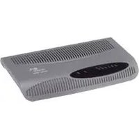
- Wireless 11n ADSL Firewall Router User Guide
- UNITED STATES GOVERNMENT LEGEND
- ENVIRONMENTAL STATEMENT
- End of Life Statement
- Regulated Materials Statement
- Environmental Statement about the Documentation
- CONTENTS
- ABOUT THIS GUIDE
- INTRODUCING THE ROUTER
- INSTALLING THE ROUTER
- SETTING UP YOUR COMPUTERS
- RUNNING THE SETUP WIZARD
- CONFIGURING THE ROUTER
- TROUBLESHOOTING
- IP ADDRESSING
- TECHNICAL SPECIFICATIONS
- SAFETY INFORMATION
- END USER SOFTWARE LICENSE AGREEMENT
- OBTAINING SUPPORT FOR YOUR 3COM PRODUCTS
- GLOSSARY
- REGULATORY NOTICES
- Naming Convention
- Conventions
- INTRODUCING THE ROUTER
- Wireless 11n ADSL Firewall Router
- Router Advantages The advantages of the Router include:
- Package Contents The Router kit includes the following items:
- Minimum System and Component Requirements
- Physical Features
- Power LED (Illuminated Logo)
- Alert LED
- A D S L S y n c
- A D S L D a t a
- Wireless LAN (WLAN) Status LED
- LAN Status LEDs (4 indicators)
- WPS LED
- Wireless Antennae
- ADSL Port
- Ethernet Ports (4 ports)
- WiFi On/Off button
- Reset Button
- Power Adapter Socket
- WPS button
- 2
- Introduction
- Positioning the Router
- Using the Rubber Feet
- Wall Mounting
- Mounting Instructions for Cement Walls
- Mounting Instructions for Wood Walls
- Powering Up the Router
- Connecting the Router
- Then:
- 3
- Obtaining an IP Address Automatically
- Windows Vista
- Windows XP
- Disabling PPPoE and PPTP Client Software
- Disabling Web Proxy
- 4
- Accessing the Setup Wizard
- Wizard - Change Password
- Wizard - Time and Time Zone
- Wizard - Connection Type
- PPPoE
- PPPoA
- Bridge Mode (for a single PC)
- Routing Mode over ATM
- Dynamic/Fixed IP in 1483 Bridge Mode (For Multiple PCs)
- Wizard - LAN Settings
- Wizard - Wireless Setting
- Security Mode
- 64-bit WEP
- Click Next.
- 128-bit WEP
- WPA-PSK (no server)
- WPA with Radius Server
- Wizard - Configuration Summary
- 5
- Welcome Screen
- Status
- LAN Settings
- LAN Settings Unit Configuration
- DHCP Clients List
- Wireless Settings
- Disabled
- WPA (with RADIUS Server)
- PIN
- ■WPS-PBC
- Connection Control
- Disable
- Bridge Mode
- Dynamic/Fixed IP in 1483 Bridge Mode
- Firewall
- Special Applications
- Virtual Servers
- Click Apply.
- PC Privileges
- Schedule Rule
- URL Filter
- Advanced
- Security
- VLAN
- Static Routes
- Traffic Mapping
- VPN The Router has a Virtual Private Network (VPN) feature that provides a
- Status and Logs
- Routing Table
- Traffic Statistics
- Support/Feedback
- 6
- Basic Connection Checks
- Forgotten Password and Reset to Factory Defaults
- Wireless Networking
- Recovering from Corrupted Software
- Power Adapter Power Status Logo not lit.
- 3Com Number Region
- Frequently Asked Questions
- How do I reset the Router to Factory Defaults?
- How many computers on the LAN does the Router support?
- How many wireless clients does the Router support?
- There are only 4 LAN ports on the Router. How are additional computers connected?
- Does the Router support virtual private networks (VPNs)?
- A
- Type One
- Type Two
- How does a Device Obtain an IP Address and Subnet Mask?
- Auto-IP Addressing
- B
- 3Com Wireless 11n Cable/DSL Firewall Router
- Interfaces
- Antenna
- WLAN Interfaces
- Operating Temperature
- Power
- Humidity
- Dimensions
- Weight
- System Requirements Operating Systems
- C
- Important Safety Information
- E
- Register Your Product to Gain Service Benefits
- Solve Problems Online
- Purchase Extended Warranty and Professional Services
- Access Software Downloads
- Contact Us
- Telephone Technical Support and Repair
- DNS Server Address
- Encryption
- Ethernet
- EU COMPLIANCE
- INDEX
- Numbers
- D
- F
- H
- |
- L
- M
- N
- P
- R
- S
- T
- U
- V
- W
Brand : 3COM
Model : Wireless 11n
Category : Router