
RKB-650 - Audio Amplifier ROTEL - Free user manual and instructions
Find the device manual for free RKB-650 ROTEL in PDF.
| Product Type | 6-Channel Power Amplifier |
| Brand | ROTEL |
| Model | RKB-650 |
| Dimensions (W × H × D) | 430 × 144 × 429 mm |
| Rack Height | 3U (132.6 mm) |
| Net Weight | 15.5 kg |
| Power Supply | 115 V/60 Hz (USA) or 230 V/50 Hz (Europe) depending on configuration |
| Power Consumption | 450 W max, 42 W average, 2.6 W standby |
| Output Power (8 Ω) | 6 × 50 W/channel (20-20000 Hz, THD < 0.03%) |
| Output Power (4 Ω) | 6 × 80 W/channel (1 kHz, THD 1%) |
| Total Harmonic Distortion | < 0.03% (full power, half power, 1 W) |
| Intermodulation Distortion | < 0.03% |
| Frequency Response | 10 Hz - 100 kHz (±1 dB) |
| Signal-to-Noise Ratio | 115 dB (A-weighted IHF) |
| Input Impedance | 20 kΩ |
| Input Sensitivity | 1 V |
| Amplification Gain | 26 dB |
| Peak Current | 25 A |
| Crosstalk / Channel Separation | 70 dB |
| Speaker Impedance | 4 Ω minimum |
| Circuit Breaker | 16 A (resettable) |
| Audio Inputs | 3 unbalanced RCA pairs, internal linking possible |
| Speaker Outputs | 3 pairs of terminals (L/R per channel pair) |
| Power-On Modes | Manual, automatic by signal detection, 12 V trigger |
| Protections | Thermal and overload (front panel LED indicators) |
| Maintenance | Clean with a dry cloth or vacuum cleaner |
| Safety | Do not expose to moisture; unplug if liquid enters; no user-serviceable parts |
| Options | Ventilation kit RKBF-2, rack mounting (brackets supplied) |
| Supplied Accessories | Rack brackets, handles, adjustment covers, screws |
| Standards | Class B, complies with NMB-003 |
Frequently Asked Questions - RKB-650 ROTEL
User questions about RKB-650 ROTEL
0 question about this device. Answer the ones you know or ask your own.
Ask a new question about this device
Download the instructions for your Audio Amplifier in PDF format for free! Find your manual RKB-650 - ROTEL and take your electronic device back in hand. On this page are published all the documents necessary for the use of your device. RKB-650 by ROTEL.
USER MANUAL RKB-650 ROTEL
PykoBoDCTBO BnaJeBua
RKB-650
Six channel power amplifier
6-KaHaJIbHOrO yCnIInTeJIb MoUHOCTHI
CAUTION RISK OF ELECTRIC SHOCK DO NOT OPEN

CAUTION: TO REDUCE THE RISK OF ELECTRIC SHOCK, DONOT REMOVE COVER. NO USER-SERVICEABLE PARTS INSIDE.REFER SERVICING TO QUALIFIED SERVICE PERSONNEL.

ATTENTION POUR RÉDUIRE LE RISQUE D'ÉLECTROCUTION NE PAS RETIRER LE CAPOT

IL N'Y A À L'INTÉRIEUR AUCUNE PIECE SUSCEPTIBLE D'ÊTRE MODIFIÉE PAR L'UTILISATEUR, EN CAS DE PROBLÉME, ADRESSEVOUS À UN RAPARATUR AGREE.

PRECAUCION RIESGO DE ELECTROCUCION NO ABRIR

PRECAUCION: PARA REDUCIR EL RIESGO DE RECIIBIR UNA DESCARGA ELECTrica, NO KUITAR LA CUBERTA SUPERIOR. NO HAS COMPONENTEN MAMPULABLES POR EL USUALI EN DEL INTERIOR DEL APARATO, CUALIER OPERATION DE MANTENIMIENTO DEBE SER LLEVADA A CABO POR PERSONAL CULIFICADO.

ATTENZIONE RISCHIO DISCOSSA ELETTRICA NON APRIRE

This Class B digital apparatus complies with Canadian ICES-003.
This symbol is to alert the user to the presence of uninsulated dangerous voltages inside the product's enclosure that may constitute a risk of electric shock.

This symbol is to alert the user to important operating and maintenance (service) instructions in this manual and literature accompanying the product.

WARNING: There are no user serviceable parts inside. Refer all servicing to qualified service personnel.
WARNING: To reduce the risk of fire or electric shock, do not expose the unit to moisture or water. Do not expose the unit to dripping or splashing. Do not place objects filled with liquids, such as vases, on the unit. Do not allow foreign objects to get into the enclosure. If the unit is exposed to moisture, or a foreign object gets into the enclosure, immediately disconnect the power cord from the wall. Take the unit to a qualified service person for inspection and necessary repairs.
Read all the instructions before connecting or operating the component. Keep this manual so you can refer to these safety instructions. Heed all warnings and safety information in these instructions and on the product itself. Follow all operating instructions.
Clean the enclosure only with a dry cloth or a vacuum cleaner.
You must allow a minimum 10cm or 4 inches of unobstructed clearance around the unit. Do not place the unit on a bed, sofa, rug, or similar surface that could block the ventilation openings. If the unit is placed in a bookcase or cabinet, there must be ventilation of the cabinet to allow proper cooling.
Keep the component away from radiators, heat registers, stoves, or any other appliance that produces heat.
The unit must be connected to a power supply only of the type and voltage specified on the rear panel. (USA: 120 V/60Hz, EC: 230V/50Hz)
Connect the component to the power outlet only with the supplied power supply cable or an exact equivalent. Do not modify the supplied cable. A polarized plug has two blades, with one wider than the other. A grounding plug has two blades plus a third grounding prong. These are provided for your safety. Do not defeat grounding and/or polarization safety provisions. If the supplied plug does not fit your outlet, please consult an electrician for replacement of the obsolete outlet. Do not use extension cords.
The main plug of the power cordset is a disconnect device of the apparatus. In order to completely disconnect the apparatus from the supply mains, the main plug of the power cordset should be unplugged from the mains (AC) outlet. The stand-by LED indicator will not be lit up to show the power cord is unplugged.
Do not route the power cord where it will be crushed, pinched, bent, exposed to heat, or damaged in any way. Pay particular attention to the power cord at the plug and where the cord exits the back of the unit.
The power cord should be unplugged from the wall outlet during a lightning storm or if the unit is to be left unused for a long period of time.
Use only accessories specified by the manufacturer.
Use only with a cart, stand, rack, bracket or shelf system recommended by Rotel. Use caution when moving the unit in a stand or rack to avoid injury from a tip-over.
Use Class 2 wiring for speaker connections to ensure proper installation and minimize the risk of electrical shock.
Immediately stop using the component and have it inspected and/or serviced by a qualified service agency if:
- The power supply cord or plug has been damaged.
- Objects have fallen or liquid has been spilled into the unit.
The unit has been exposed to rain.
The unit shows signs of improper operation - The unit has been dropped or damaged in any way
1: Controls and Connections
2: Hook-up Illustration
Important Safety instructions! 4
1: Controls and Connections 8
2: Hook-up Illustration 9
About Rotel 10
Getting Started. 10
Features. 11
A Few Precautions 11
Placement 11
Rack Mounting. 11
Rack Handles 11
Optional Fan Kit 5 11
AC Power and Control 12
AC Power Input 12 12
Power Switch 1
Indicator LED 2 12
Auto Turn On/Off Mode Selector 9 12
12V Trigger Input 8 12
12V Trigger Output 8 12
Circuit Breaker 11 12
Protection Indicators 3 12
Signal Connections 13
RCA Inputs 6 13
Linking the Inputs 13
Input Level Controls 4 13
Signal Output Link 7 13
Speakers 13
Speaker Selection. 13
Speaker Wire Selection. 13
Polarity and Phasing. 13
Speaker Connections TO 14
Troubleshooting 14
Front Panel Power Indicator Is Not Lit. 14
No Sound 14
Protection Indicator Is Lit. 14
Specifications 14
About Rotel
A family whose passionate interest in music led them to manufacture high fidelity components of uncompromising quality founded Rotel over 40 years ago. Over the years that passion has remained undiminished and the goal of providing exceptional value for audiophiles and music lovers regardless of their budget, is shared by all Rotel employees.
The engineers work as a close team, listening to, and fine tuning each new product until it reaches their exacting musical standards. They are free to choose components from around the world in order to make that product the best they can. You are likely to find capacitors from the United Kingdom and Germany, semiconductors from Japan or the United States, and toroidal power transformers manufactured in Rotel's own factory.
Rotel's reputation for excellence has been earned through hundreds of good reviews and awards from the most respected reviewers in the industry, who listen to music every day. Their comments keep the company true to its goal – the pursuit of equipment that is musical, reliable and affordable.
All of us at Rotel thank you for buying this product and hope it will bring you many hours of enjoyment.
Getting Started
Thank you for purchasing the Rotel RKB-650 Six Channel Power Amplifier. When used in a high-quality music or home theater system, your Rotel amplifier will provide years of musical enjoyment.
The RKB-650 is a sophisticated six-channel power amplifier. Discrete output devices, a massive power supply with toroidal transformer, premium components, and Rotel's Balanced Design ensure superb sound quality. High current capability allows the RKB-650 to drive difficult speaker loads with ease.
Features
- Six-channel power amplifier, with 50 watts per channel output into 8 ohms.
- Rack-mountable (standard international 3U rack height). Rack handles or the rack mount kit can be removed for installation in narrower spaces.
- Front panel input level controls. Can be configured three ways: recessed adjustments, knobs for user control, or covered with blanking plugs to prevent user adjustment.
- User-selectable power on/off configuration: manual, automatic signal sensing, or controlled by remote 12 volt trigger signal.
- Provision for installation of optional cooling fan for increased heat dissipation and performance.
- Protection circuitry against fault conditions with front panel indicators.
A Few Precautions
Please read this manual carefully. In addition to basic installation and operating instructions, it provides valuable information on various RKB-650 system configurations as well as general information that will help you get optimum performance from your system. Please contact your authorized Rotel dealer for answers to any questions you might have. In addition, all of us at Rotel welcome your questions and comments.
Save the RKB-650 shipping carton and all enclosed packing material for future use. Shipping or moving the RKB-650 in anything other than the original packing material may result in severe damage to your amplifier.
Keep the original sales receipt. It is your best record of the date of purchase, which you will need in the event warranty service is ever required.
Placement
The amplifier can be mounted in a standard equipment rack or placed on a solid surface.
When not using an equipment rack, place the RKB-650 on a solid, level surface away from sunlight, heat, moisture, or vibration.
Don't stack other components or objects on top of the RKB-650. Don't let any liquid fall into the unit.
Likewise, remember the weight of the amplifier when you select an installation location. Make sure that the shelf or cabinet can support its considerable bulk.
The RKB-650 generates heat during normal operation. Do not block ventilation openings. Allow a minimum of 10cm or 4 inches of unobstructed space around the unit. If installed in a cabinet, make sure that there is adequate ventilation.
Rack Mounting
The RKB-650 is supplied with two rack mounting brackets for installation in standard equipment racks. To install these brackets:
- Hold a bracket against the side of the amplifier to locate the chassis cover screw that must be removed for clearance. Remove this screw with a Phillips head screw driver and replace it with one of the short Philips head machine screws enclosed with the brackets.
- Install the rack mount bracket, inserting three of the long Philips head machine screws through the bracket and into the threaded holes in the side of the amplifier.
- Repeat for the bracket on the other side of the amplifier.
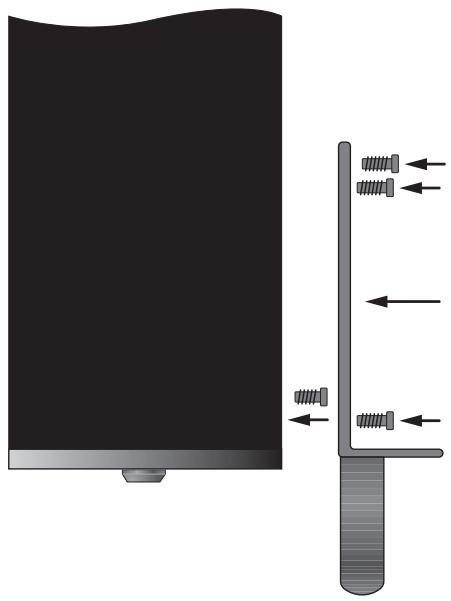
NOTE: You can remove the feet from the bottom of the amplifier if necessary for clearance in the rack. Save the feet and hardware for future use.
After the adaptors are installed, use four bolts supplied with your equipment rack to mount the amplifier. Be sure that all four bolts are tightened properly.
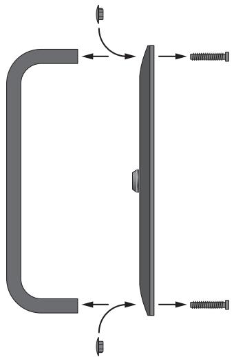
Rack Handles
The rack mount brackets are supplied with handles which can be installed or removed. The handles are installed with two of the long Philips head machine screws inserted through the rack mount bracket and into the threaded holes in the handle. If you do remove the handles, use the rubber hole plugs supplied with the bracket hardware to fill the exposed holes.
Optional Fan Kit 5
The RKB-650's generous heatsinks provide adequate cooling for most installations. However, when rack mounting or otherwise installing the amplifier in a confined space near other heat-generating components, additional cooling may be desirable. The optional RKBF-1 fan kit can be easily installed for additional forced air cooling. In addition to lowering operating temperatures, the optional fan kit improves the performance of the amplifier, especially when driving difficult loudspeaker loads. See your Rotel dealer for information on the optional fan kit.
NOTE: The optional cooling kit generates mechanical fan noise during operation. When using the fan cooling, select a location for the amplifier where the noise will not be intrusive.
AC Power and Control
AC Power Input 12
Your RKB-650 is configured at the factory for the proper AC line voltage in the country where you purchased it (USA: 120 volts/60 Hz, Europe: 230 volts/50 Hz). The AC line configuration is noted on a label on the back panel.
The RKB-650 is supplied with the proper AC power cord. Use only this cord or an exact equivalent. Do not modify the supplied cord. Do not use an extension cord.
Be sure the power switch on the front panel of the RKB-650 is turned off. Then, plug one end of the cord into the AC power connector on the back panel of the amplifier. Plug the other end into an appropriate AC outlet.
If you are going to be away from home for an extended period of time, it is a sensible precaution to unplug your amplifier.
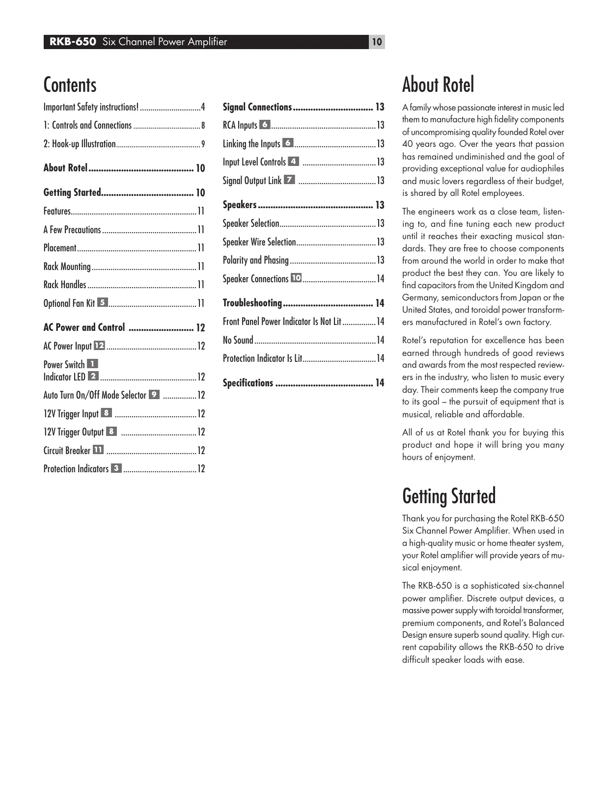
Power Switch 1 Indicator LED 2
The power switch is located on the left side of the front panel. To turn the amplifier on (or to activate either of the optional automatic power-on modes), push the switch in. The LED indicator above the switch will light, indicating that the amplifier is turned on. To turn the amplifier off, push the button again and return it to the out position.
Auto Turn On/Off Mode Selector 9
The RKB-650 provides three different options for manual or automatic power on/off operation. These modes are selectable using a three-position slide switch on the back panel as follows:
-
With the switch in the OFF position, the amplifier is turned on or off manually using the front panel power switch. Also use this mode if you are using a switched AC outlet to control power to the amplifier.
-
With the switch in the SIGNAL SENSE position, the amplifier turns on automatically when a signal is detected at the inputs. The amplifier will go into standby mode several minutes after no signal is no longer present. The front panel power switch overrides this function. It must be ON for the signal sensing to work. Turning the switch OFF cuts power to the amplifier, regardless of whether or not a signal is present.
- With the switch in the 12V TRIG position, the amplifier is turned on automatically when a 12 volt trigger signal is present at the 12V TRIG input to the left of the switch. The amplifier goes into standby mode if the +12 volt signal is not present. The front panel POWER SWITCH overrides this function. It must be ON for the +12V trigger to work. Turning the switch OFF cuts power to the amplifier, regardless of whether or not a trigger signal is present.
12V Trigger Input 8
An input jack for connecting the wires carrying a +12 volt trigger signal from a Rotel preamp or surround sound processor to turn the amplifier on and off. To use this feature the adjacent slide switch must be placed to the left position (see previous section).
The TRIGGER INPUT accepts any control signal (AC or DC) ranging from 3 volts to 30 volts. Using a cable with mono 3.5mm mini-plugs on both ends. The +12VDC signal appears at the "tip" connector.
12V Trigger Output 8
The 12V TRIG jack labeled OUT is used to pass the remote turn-on signal to a second Rotel amplifier. Any 12V Trigger signal at the INPUT jack will be passed through to the OUT jack.
Circuit Breaker 1
A 16 amp circuit breaker on the rear panel protects the amplifier's electrical circuit. Generally, the circuit breaker will only open under a fault condition which results in excessive current draw. To reset the circuit breaker, press the button. Should it repeatedly open, contact your authorized Rotel dealer for troubleshooting assistance.
Protection Indicators 3
A thermal protection circuit protects the amplifier against potential damage in the event of extreme or faulty operating conditions. Unlike many designs, the RKB-650's protection circuit is independent of the audio signal and has no impact on sonic performance. Instead, the protection circuit monitors the temperature of the output devices and shuts down the amplifier if temperatures exceed safe limits.
In addition, the RKB-650 includes overcurrent protection which operates only when load impedance drops too low.
Should a faulty condition arise, the amplifier will stop playing and one or more of the PROTECTION LEDs on the front panel will light.
If this happens, turn the amplifier off, let it cool down for several minutes, and attempt to identify and correct the problem. There are independent PROTECTION LEDs for each pair of channels which may help in troubleshooting the cause of the problem. When you turn the amplifier back on, the protection circuit will automatically reset and the PROTECTION LEDs should go out.
In most cases, the protection circuitry activates because of a fault condition such as shorted speaker wires, or inadequate ventilation causing an overheating condition. In very rare cases, highly reactive or extremely low impedance speaker loads could cause the protection circuit to engage.
Signal Connections
The RKB-650 provides standard conventional input connections — unbalanced RCA type connections as found on nearly all audio equipment.
There is also a pair of SIGNAL OUTPUT LINK connections for passing the input signal connected to the "A" pair of channels on to another audio component. Additionally, the input signal to the "A" pair of channels can be automatically linked to the inputs for the "B" and/or "C" channels, so that a separate input signal cable is not required for those channels, for example in large systems where the RKB-650 is being used to drive multiple pairs of speakers.
RCA Inputs 6
See Figure 2
There are two RCA inputs for each of the three pair of amplifier channels. These RCA inputs accept audio signals from preamplifiers or surround sound processors. Use high quality audio interconnect cables for best performance.
For each pair of amplifier channels, connect the left channel output of your preamp to the LEFT INPUT on the RKB-650. Connect the right channel of your preamp to the RIGHT INPUT. Make sure that the input slide switch to the right of the RCA inputs is in the STE-REO position.
Linking the Inputs 6
You can link the inputs for groups "B" and/or "C" to the "A" inputs by placing the input slide switch to the right of each pair of RCA inputs in the LINK position. When linked, no input connection is required for that group. The input signal from the "A" group is sent to the linked pair of channels, allowing you to use four or six amplifier channels with the same stereo input signals.
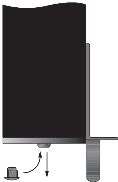
Input Level Controls 4
Three controls on the front panel, one for each pair of channels, provide input level adjustments. These allow you to adjust the gain of the amplifier to match other components in the system. The A level control changes the gain of the "A" channels; the B level control changes the "B" channels; the C level control changes the "C" channels.
To adjust these controls, use a small, flatblade screwdriver. Turn the control clockwise to increase gain. Turn counterclockwise to reduce gain.
For easier adjustment, install the supplied volume control knobs by gently pressing them onto the control shafts. Alternatively, you can prevent inadvertant adjustment by installing the supplied rubber plugs to conceal the volume controls.
Signal Output Link Z
This pair of RCA connections can be used to pass the unprocessed input signals to another audio component, for example to "daisy-chain" an additional amplifier to drive a second set of speakers. The input signals connected to the "A" channels is also available at these LINK outputs.
NOTE: These input signals from the "A" channels can also be linked to the "B" and/or "C" inputs by playing the INPUT SELECT switch associated with that pair of channels in the LINK position.
Speakers
The RKB-650 has three groups of speaker connectors, one for each pair of amplifier channels.
Speaker Selection
The nominal impedance of the loudspeaker(s) connected to the RKB-650 should be a minimum of 4 ohms. When driving multiple pairs of speakers connected in parallel, the effective impedance the amplifier sees is cut in half. For example, when driving two pair of 8 ohm speakers, the amplifier sees a 4 ohm load. When driving multiple speakers in parallel, select speakers with a nominal impedance of 8 ohms or higher.
Speaker Wire Selection
Use insulated two-conductor stranded wire to connect the RKB-650 to the speakers. The size and quality of the wire can have an audible effect on the performance of the system. Standard speaker wire will work, but can result in lower output or diminished bass response, particularly over longer distances. In general, heavier wire will improve the sound. For best performance, you may want to consider special high-quality speaker cables. Your authorized Rotel dealer can help in the selection of appropriate cables for your system.
Polarity and Phasing
The polarity or positive/negative orientation of the connections for every speaker and amplifier connection must be consistent so all the speakers will be in phase. If the polarity of one connection is mistakenly reversed, bass output will be very weak and stereo imaging degraded. All speaker wire is marked so you can identify the two conductors. There may be ribs or a stripe on the insulation of one conductor. The wire may have clear insulation with different color conductors (copper and silver). There may be polarity indications printed on the insulation. Identify the positive and negative conductors and be consistent with every speaker and amplifier connection.
Speaker Connections 10
See Figure 2
The RKB-650 has two pair of color coded connections for each group of amplifier channels, one for the left speaker, the other for the right speaker. Labels above the connectors show the proper connections for connecting speakers. These speaker connectors accept bare wire, connector lugs, or "banana" type connectors (except in the European Community countries where their use is not permitted).
Route the wires from the RKB-650 to the speakers. Give yourself enough slack so you can move the components enough to allow access to the speaker connectors.
If you are using banana plugs, connect them to the wires and then plug into the backs of the speaker connectors. The collars of the speaker connectors should be screwed in all the way (clockwise).
If you are using terminal lugs, connect them to the wires. If you are attaching bare wires directly to the speaker connectors, separate the wire conductors and strip back the insulation from the end of each conductor. Be careful not to cut into the wire strands. Unscrew (turn counterclockwise) the speaker connector collar. Place the connector lug around the shaft, or insert the bundled wire into the hole in the shaft. Turn the collars clockwise to clamp the connector lug or wire firmly in place.
NOTE: Be sure there are no loose wire strands that could touch adjacent wires or connectors.
For each group of channels, connect the left speaker to the pair of speaker connectors labeled LEFT. Connect the right speaker to the speaker connectors labeled RIGHT. Follow the labels printed above the connectors, Make sure that the positive terminal of the speaker is connected to the + terminal on the amplifier. Make sure that the negative terminal of the speaker is connected to the - terminal of the amplifier.
Troubleshooting
Most difficulties in audio systems are the result of poor or wrong connections, or improper control settings. If you encounter problems, isolate the area of the difficulty, check the control settings, determine the cause of the fault and make the necessary changes. If you are unable to get sound from the RKB-650, refer to the suggestions for the following conditions:
Front Panel Power Indicator Is Not Lit
No main power to the RKB-650. Check AC power connections at the amplifier and the AC outlet. Check the front panel power switch. Make sure that it is set to the ON position. If using signal sensing auto power-on, make sure that a signal is present at the inputs. If using 12V trigger power-on, make sure that a trigger signal is present at rear panel 12V TRIG IN connector.
No Sound
If the amp is getting AC power, but is producing no sound, check the PROTECTION INDICATORS on the front panel. If lit, see below. If not, check all of your connections and control settings on associated components.
Protection Indicator Is Lit
The front panel PROTECTION INDICATORS light when the RKB-650 protection circuits have shut off the amplifier. Typically, this occurs only when the ventilation openings are blocked, when there is faulty speaker wiring, or after a period of extreme use. Turn off the system and wait for the amp to cool. Then push the front panel power switch in and out to reset the protection devices. If the problem is not corrected or reoccurs, there is a problem with the system or the amplifier itself.
Specifications
Continuous Power Output into 8 ohms (20-20k Hz, < 0.03% THD)
6x50 watts/ch into 8 ohms, all channels driven
Continuous Power Output into 4 ohms (DIN 1 kHz, 1.0% THD)
6 x 80 watts/ch into 4 ohms, all channels driven
Total Harmonic Distortion (20Hz-20kHz, 8 ohms)
Continuous rated power: < 0.03%
One-half rated power: < 0.03%
1 watt power: < 0.03%
Intermodulation Distortion (60 Hz: 7 kHz, 4:1)
< 0.03%
Damping Factor
(20-20,000 Hz, 8 ohms)
200
Input Impedance
20 k Ohms
Input Sensitivity
1.0 volt
Amplifier Gain:
26 dB
Input Overload Level
5.0 volt
Peak Current
25A
Frequency Response (±1 dB)
10Hz-100kHz
S/N Ratio (IHF A)
115 dB
Crosstalk/Separation
70dB
Speaker Impedance
4 ohms minimum
Auto Turn On Level (with all inputs)
1 mV input signal
Power Requirements
USA: 120 Volts, 60 Hz
Europe: 230 Volts, 50 Hz
Power Consumption
450 Watts
Idle: 42 Watts
Standby: 2.6 Watts
Dimensions (W× H× D)
(not including rack adaptors)
430× 144× 429mm
16.9 × 5.7 × 16.9 in
Weight (net)
15.5 kg, 34.1 lb.
Panel Height
3U, 132.6 mm/5.2 in
When sizing openings in custom cabinets, measure the unit to be installed and/or allow at least 1 mm clearance on all sides for unit to unit tolerances.
All specifications are accurate at the time of printing. Rotel reserves the right to make improvements without notice.
Rotel and the Rotel HiFi logo are registered trademarks of The Rotel Co, Ltd., Tokyo, Japan.
Sommaire
15^5kg
Altura del Panel Frontal
3U, 132'6 mm
16.9 × 5.7 × 16.9 in
Peso (netto)
15.5 kg / 34.1lb.
Signal Output Link 7
2.6 Watts in "standby"
Afmetingen:
430x144x429 mm. (bxhxd)
Netto gewicht:
15.5 kg
(DIN 1 kHz, 1,0 % THD)
BbIKIIOUaTeJIb NITaHnI 1, CBeTOdNOdHbI INHdNKATOp 2
BbIKIOUATEbIITAHnIpaCnONOKeHcneBaHa nepeDHeI paHEnI yCINlTeN.ДЯ BkIOUeHnYcINlTeN(HnI dIaAKTbAuznKakoro-Nb6o peKIma ABtOMaTHeCKOrO BkIOUeHnI),HaxMITE Ha BbIKIOUATeB.CBeToIDNoHbI INHdNKATOp HAD BbIKIOUATeMe 3aORpNTc, NOKa3bIBa, YTO yCINlTeBbKIOUeH. YTo6blBbIKIOUHTbYcINlTeB, HAXMITE Ha KhONkY eEe pa3 n BepHIne ee B NOLOXeHne «BbIKIOUeHO»
PpeeknlooyateIb pexmabBtOMaTHueckoro BKIOUeHn/ByIKIOUeHn 9
RKB-650o6ecneuBaetnpa3nHbIX Bo3moXhoCTnДЯpyHOrO HnI ABTomatueckoro BkIoUeHnER/BykIoUeHnER NtAHn.3npeKmbl Bi6HpArTcR npn NpOoN TPexNo3nOHHOr O DvIKKOBOrOpeknOuTeHa 3aDHe nanei:
Korda daHbI nepeKnIOuateIb haxoIYcBnOxKeHN OFF,ycnInTeIb BKIOUaOT N BvIKNoUaOT BpyHyTO npi nOMOsi KNOpKN Ha nepeJeHn NaHeN. 3TOT pExHM TAKJE HcNoJIb3yJte,ecnn Ba7a po3ETKa nepemEnHO TOka cHa6KeHa bIKIOuATEIeM dIra ynpabNeHn IOnaueh NITAHNA HA ycINInTeIb;
Korda nepekliouateb haxoantcB noloxeHHN SIGNAL SENSE, ycnlnteB BKIOVAETcABTOMaTHueckn npn o6hapykeHHN cHrHana ha BxOaX. YcnlnteB nepeiDeT B XJdyu nn pexm ue3 HeckonbKO MnHyT nocne Hcye3HOBeHHa. KOnka Ha nepeedNe paHEn 6boknyet 3Ty fynkuio. OHa DOnjHa 6bITb B noloxeHHN ON, yTo6bl cxema o6hApykeHHN cHrHana pa6otana. Nepekniouehne KOnkN B noLoxeHHne OFF OKILOUaETnHTAHne OTyCNlNTeN, He3abVCmo OT TORO, npncytCTByET cHrHAn IIN Het;
Korda nepeknoquatelb haxoantcB nooxeHH 12V TRIG, ycnntenB BknouaetcABOMATnueckn npn noBleHH 12-BonbTOBOrO cHrHaHa Ha BXoJe 12VTRIG cneBa oTnepeknoquatel. Ycnntenb nepexodHT B Xdyuyn peXm,ecn 12-BonbTOBbI CNTHANOTCYCTByet.KhONka POWER SWITCH Ha nepeDnei naHenn6boknpyET 3Ty fynKcuio.OHa DOnJxHa HaxoDHTbcraB nONoXeHH ON, yTo6bl 12-BonbTOBbI 3anyckaIOuSH cnHAn pa60tAn. NepeKniouehne KhONKn B nooxeHH OFF OTknOuaet NITAHne OT ycInNTeN, He3abNCmo OTTO, pncytCTbyET 3anyckaIOUsh CnIHAN INH HeT.
Bxo12V Trigger 8
BxoJHoe rHe3do InpncOeHHnKa6en, HecyIero 12-BoIbTOBbI 3anycKaIOuIcn cnHAn ot npedBaPntelbHorO ycInntela ROTEL nPioueeccopa OkpykaIOoero 3Byka, npedHa3NaHcENHO IIN BKIIIOUeHn IN BbIKHOueHn ycInntela. YTo6bl peaIIN3OBaT b 3Ty fynKcuHIO, cocEnHn DvNkKobI nepeKIOUaTeNb DOJIKeH haxOJNbCB B IeBOM NOnOKeHN (CM.npeBbIyUnn pa3den).
3aynyckaiouBxodTRIGGERINPUTnpnHnmaet 1IO6o ynpablahoosin CnHan (nepeMeHHoro nnoCTOraHHoro ToKa) B dHaPnA3OHe oT 3do 30 BoIbT. NcNoIb3yeT Ka6eNb c MoHOfoHNuecknMn 3,5-MM «MmHnDJIeKAMn» c 6OOnx KOHcOB.CnHan +12 B NoBraTeCn Ha «KOHUKe» pa3BeMa.
BbIXoJ 12VTRIGGER 8
THe3do,06o3haueHHoe 12VTRIGOUT,ncnObl3yetc
IpyonysckanHnIcnctaunOHoro cHana
BknIOeHNHa BTOPOHycnHtEnb ROTEL. HIO6o
3anyCkaHsN CNrHaN 12 B Ha BxOdHOM THe3de
6yET npepaH Na BbIXoHoe THe3do.
YcTPOIcTBO OTKJIoueHnI
16-amnepbny pa3mbikateb ceHn Ha 3aDneHn aeHn 3aunuaeT nektpnueckne cxemby ycnnten. B 06uem cnyue, pa3mbikateb ceHn cpa6otaet tonbko npn HeNCnPabHom coCToHn, KOTOpoe npNBOHT K n36bItoHOMy Notpe6NeHnTOka. Ecnn OH noCToHNO pa3mbiKaetc, o6patntecb K bawemy ABtopn3OBAHHom dyInepy ROTEL a naDpeKko B dHaTHOCTnke HeNCnPabHOctn.
HdNkaTOpbl3auntbl 3
Cxembl Tenubo3aunbI npedotBpaanaot noteuunbHoe nobpeJdeHne ycInntela Bcnyae 3KCTpeMaJIbHbIX CHTyaun HnN COCTOHNOTka3a. B OTNHue O TMHONx Dpynx ycInnteNe, cxema 3aunbTI RKB-650 He 3aBnCtOT 3BykoBOrO cINHana n He BnAET Ha KaueCTBO 3BykoBOcnpOn3BeDeHn. BMeTo 3TOrO, cxema 3aunbI OTCLeXnBaet tempepatybl BbIXoDhbl TpAn3nctOpOB n OKnIOUaET ycInntel, ecnn OHn npBbIaOT 6eONacHbIe npednl.
Kpome toro, RKB-650 cha6xeh 3auntoi ot npebblweHnraToKa, KOTOPa cpa6aTaBaetTOnbko ecnnmpeDnC Harpy3Kn CTAHOBNTc CnNkOM Hn3KM.
PnHactynneHHN Oka3a, YcHnIeJIb octAHOBIT BocpOn3BeDeHHe, HOnn Hn6Oonee CBToDnOIOB PROTECTION LEDs 3aropTcHa nepeDneH naHenn.
Ecnn 3to npoHOniTe, BbKlIOuHTe ycHnnteB, daIte EmO octItb HeCKoNbKO MInHyT nNONbTaIaTeCb 6bnapyKHTb NcnpabNTb np6bemy.ДЯKaJdoI napbl KaHAnOB cyueCTbYOT cBOH INdNKatOpbl, KOTopbl eMOrYT NOMOy B ONpeJeHEn pPrUnHb HncnPabHocn. Korda Bbl BklnOuaTe ycHnnteB CHOBA, CXEMA3aUHTbl ABTomAtNuYeCKn c6pacbBaetcN INHdNKATOpbl rachyt.
B 60nbshnHCTBe cnyaeB, cxema 3auntbakTNbpyetc B pe3yIbIate HecncpabHOctn, tako KaK KopOTKe 3AmblKaHne B AkyCTnueckOM ka6ene HnHnOCTatoUHna BeHTnlaZn. B OuyhpekKnxCnyaX, cpa6atbIbAHne CXembl3auntb MoKet ObcNobTb BbICOKaPeAKTNBHOCTb HnHpe3bVauHn Hn3Kn HmpeDaHc rPOMKOROOpNTeHa Harpy3Kn.
Pa3bemblI nHaIOB
RKB-650 o6ecneuHbaet cTahapThbie, 6o7euyotpe6ntenbIbe BxOaHbIe pa3bEmbl - HeCnMMETpuHbIe TINa RCA, KaKNe MoXHO HauTn NOUTH BO BCEM 3ByKObOM O6OpyIOBaHIn.
CyueCTByeT takxe napa pa3bEmoB SIGNAL OUTPUTLINK npepaun BxOHO rCnHana, noKnIOUeHHoro K nape KaHaoB A',Ha npyroe 3ByKOoe o6OpuOBOAHne. IOnONHtEnbHO, BxOHO CNrHn napbl KaHaoB A'MoKet 6bIb ABToMaTHueCKn pnpcoEHNHe N BXoAM KaHaoB B'N/INN C'TaK, YTO6bl dNAn EtnX KaHaoB He Tpe6OBanc OtdenbHbIMBXOHO Ka6enb, HApnpMeR, B 60nbWOn cnCTeme, rDe RKB-650 nCnoNb3yETc4nPa6ObTi CHeCKONbKmMn rpOMKOrOBOpnteMaN.
BxOaB1 RCA 6
Cm.pncyHOK2
Дякади n3 trex nap kahanob ycninte cyuectbykOTDBA BXODA RCA. 3TNBXOblprnHMAOT 3ykoBbIe cInhAlbl OTnpedBaPHTe hBHX yCNINTe ne Hn npoueccopoB okpykaUoJero 3Byka.ДЯ obecneueHnaHnyuHnXnapaMeTpoB,ncnonb3ynte 3ykoBbIe MeK6NochIbe Ka6eHn BlicOKOTO KAueCTBA.
Дя каду пары канов усунтета, npсоeннгte bixoNeвoro KaHana BaWoero npedbapntenbHorO ycunntetЯ Kbxody LEFTINPUT ycunntetra RKB-650. Bixo npaboro kaHana npedbapntenbHorO ycunntetЯ npсоeннite k Bxody RIGHT INPUT. OBecepeyte, tO6bl nepeknouateb INPUT SELECT haxoHnncB noLoxeHH STEREO.
CoprajxehneBXoIOB 6
BbMOKTe pIncoeHNHb XoNbI IaI rpynnIb «B» N/ nn «C» K BxOaAM «A»,pepeDINHyB nepekNIOUaTeIb INPUT SELECT nTOn IpynnIb B noLoXeHne LINK. B 3OM noLoXeHnI, IaI daHNOI pynnIb He tpe6yETc BxOJHOe coeHNHe. BxOHOH cINHAN rpynnIb «A» nepeDaetc Ha cOpJKeHHyIO npy KaHAnOB, PO3BOJIa BAM INCNoJIb3OBaTb YteJIbe IINI WeCTb KaHAnOB ycNInTErCA OINHM hCTOCHNKOM BXODHOrO cTepeo CInHana.
YnpabneHne
BXOДнБIM ypOBHEM

Iodctpoiky BxOndHOro yOBnBa o6ecneuBaoT trn orpHa ynpablenra Ha nepeDnei panen -no ONDHY kKaJdo npbl KaHAnob. OHn PO3BOJrOT BAM OTpeYlnPOBAtb Ko3ΦnUeHT nepeDaun YcNInTeNa, YTO6bl OH COOTBeCTBOBAn dpyHM KOMNoHEtAM DaHHo CnCTeMbI. PeryIaTOp yOBn KaHAnOB «A» N3MeHReT Ko3ΦnUeHT nepeDaun KaHAnOB «A»; «B» N3MeHReT Ko3ΦnUeHT nepeDaun KaHAnOB «B»; «C» - KaHAnOB «C».
Дл постюн успьуITE He6oNBsyO OTBeRTK C nnockm wHnQOM. ПOBepHnTe perynlTOp no yacoboi CTpeNke dny yBENuHnK Ko3ΦHnEHTa nepeDau. ПOBepHnTe perynIToP npTb Yacoboi CTpeNk dny yMeHbSeHnK Ko3ΦHnEHTa nepeDau.
Дя оьлсчени руглировки, установite ручкидя руглировannahуromkoctи, noctablanembleвkomпнекte, магко habадинх ha och pereynatopob.В kaucentbe anbtepeharnbbl, bbl moxete npedotbrpatntb cnyaHyIO NOCTPOKy, uctahOBHB pe3HNOBbIe 3aflnykN, takxe n3 komпнекta NOCTABKN, yTO6bl 3amacknpoBaTb pereynatopbl rpoMkoctn (cM. pncyHOK).
OTBetBJIeHne
BbIXOJHORO CnHana7
Iapa pa3bemOB RCA MoKet6bIt NcNoB3OBAHa dIa nepeaun Heo6pa6otAHhIx BxOdBHX cnHAnOB Ha dpuro 3BykoBoi KOMnoHent, HapnMep, Ia KaCKaHropOBAHn DOONHtEnbHOrO ycInnten, pa6otaUoJero Ha BtOpoi KOMnKeT rpoMkoBopHTeNe. BxoHbIe CnHbIb, npncOeHNHeHHbe K KaHanam «A», DoctynHbI takJe dIa nepeaun Ha 3TN BixOdbI LINK.
ПИМЕЧАНО:ЭТВ BXODHьСИнHAЛы OT KAHAлов «A» можно takke пиноeДиНь K BXODAM «B» n/нл«C» рпюпomoши поеклIoчateЯI INPUT SELECT, cBa3aHHoro C daHHo napoi KaHAnOB B noLoKeHn LINK.
Громковорптун
YcHnnteB MoOuHocTn RKB-650 mMeet Tpr npynbipa3bEmoB nIra rpoMkoROBOpTeNei, no OHOJ nJa kKaJdo Napbl KaHaNob ycHnnteJ.
Bb6op rpoMkoROBOpTeTn
Homnabhoe Bxodhoe conpoTnbHene rpomKorOBopntenr (rpomKorOBopnten), npcoeHHHO RKB-650, He donxHo 6bIb Mehwe 4 OM. Korda hckonbko nap rpomKorOBopnteney coeHHbnapannenbho, DeictbnbHO copotNBHeHne Harp3kn, KOTOpoe OoUyaaet Ycunntelb, yMehbwaetc HanaONOBHy. HanpHmep, npn pa6ote Ha Dbe napbl 8-OMbIX rpomKorOBopnteney, ycunntelb oOyuaet Harp3ky 4 OM. Korda pa6otaHOT HeckonbKO rpomKorOBopntenB napanenb, Bby6npaTe rpomKorOBopntenC homHaJIbHbIM cOnpoTnbHennem 8 OM nInn Bbiie.
Bb6op akyctnueckoro ka6ena
IcnoIb3yIte hOIOPOBAAHbI DByUXPBOAoHOJCKpyeHHb Ka6eJI bIgI npICoEINHeNRA RKB-650K rPOMKOOBOpHTeJIaM.Pa3MeP IN KauCteBO npOBoAHaMEOT CbIshmOe BInHHe Ha napAMetpbI cHCTeMbI.CaHdAPTHbAkCyCTueckKn Ka6eJI b6dET pa6OtATb, HO MOKeT pINBeCTn K ChNXeHNIO rPOMKocTHn HIN Ocna6NeHIO Hn3KNx YactOT, Oc6EHHO HA 6OnbHexpaccSTOrHnx.BO6eM cnyuae, 6OoneToCTbIKa6eJI yNyUshaet3ByaunHe.InNAHnPyuHX npAMePTOB,BblMOKeTe npIMeHtB cneuAnbHbIe AkCyCTueckNe Ka6eJIb BILcOKoroKaueCTBa.BaawABTOPi3OBaHHbDInepROTELMOKeT NOMOy BAM B Bbl6ope COOTBetCTByIoXKa6eJI dRBAWe CNCTeMbI.
PonpaHocbNΦa3npOBka
Pnonpnoctb nnn noonoxhtenbna/otnpaateNbnaopneHTaue coeHHn nn KaJdoTOrpomKorOBOpntEnI dOnXhbl 6bITcOrnacobHbI, YTObBce rpoMkoBOPntENbIN B a3e.Ecnnnonpnoctb odHoro coeHHn Hn OoHN6Ke cDenaha o6paTHOH, 3ByaHnE Hn3KnXyactOT6ydet ouehb CnabIM, a ctepeokaptnHa derpaHpyet. Bce akyctuneckne ka6enn npomapknpoBaHbI, YTObBb MOrNI OTnNHT bBA npOboDnHa. 3To MoxET 6bITb NOnoca Hn pNphiNeHn Ha 3Olaqnn OdHoro npOboDnHa. Ka6enb MoxET mMeTb P03paHyIO hONLAuHc n npOboDnKaMn pa3HOrO zbeta (MeHnb I cepe6pRbH). 3To MOryt 6bITb MTeKN PNOPAHOCTN, HaneYataHHbI Ha 3Olaqnn. OnpedNTe noonoxhtenbHbI n OTPcuatepenbHbI npOboDnKn I corlacyIe c KaJdbIM pa3bEMOM rpomKorOBOpntEnI yCnInTeJI.
PnncoeDnHeHne rPOMKOrOBOpnteNei 10
CM. pncyHOK 2
Ycunntenb moohocn RKB-650 nmeettn npabpa3beMOB CzBEtOBo MapknropbKOJ nJa KaKdoI rpynbKaHaoNob ycunnten, OHa napa - Inpa Bo rpoMKorOBopNTen, Dpyra npa - InpaBoHO. Ha3BaHnHa nad pa3bEmAmn noka3bIAOT HndLejaxune pa3bEmbl nJa npncOeHNHeHrpoMKorOBopNTen. 3TN pa3bEmbl npNHmHaOT 3auHnEHhBn IpOBoH, HakoHeuHKnHTnA «NonatKA» INI «6aHAn» (3a NCKIOUeHNem EbponeckxCTpah, rne IH npImeHHe 3anpeSeHo).
Прожнite npoboda ot RKB-650 K rpoMkoB OpornteЯm. Octabte Дя сея дoctatoчный 3anac,чTo6bI Hmetb Bo3MoXHocTb nepemsehenia KOMnoHETOB C celenbIO doCTyna K pa3bEmam rpoMkoBOpNTe nei.
Ecnn Bbl npmehre Te wtekepbI - 6aHaHbI, npcoeHNHTe Hx K npoBOMn 3aTeM BCTABBe B pa3beMbI rpoMKorOBopntene. 3axmHbIe Btyn pa3beMOB rpoMKorOBopntene JOnJXhIb 6bTb 3abHHeHb Ha BCIO dInHy (no YacobOc CTpeKe).
Ecnn Bbl nCnObn3yete «NonatKn», cMOHTnpuyte Hx Ha npoBoda. Ecnn Bbl npincoeHNHaeTe 3aHnueHHbIe Ka6eHn HenocepdtBeHHo Kpa3bEmam rPOMKOrOBOpHTenei, OTdEnIte npoBOnHKNi CHNIMTE N3OJaUNo C KOHcKaXJDoR npoBoda. ByIbe BHNMaTeBhl, YTO6bl He NobpeHtB tokopnoBDAJnE XINbl. OTBnHTnte (npOTNB acBOO CTpeKN) 3aJxHMHyO BTVNKp3bema
rpoMkoTOrOBOpHTe. PacnoIooJIte HakoHeuHnK BOKpyr OCN BtynKn, nII npocUhTe orOleHHbI npoBOvB OTBepCTne B OcN. 3aBePHTe BtynKy no qacobOy CTpeKe, yTO6bl HAeJxHO 3aΦHKCpOBaTb HakoHeuHnK nII npoBOiD.
PIMMEUHNE: Oecneyte, yto6bI OTeJIbHbIe Xnbl npoOa He moRn Kacatbcra cocedHnx npoBOOB nI npa3bEmOB.
Дя каду рупьк саналов, псиоэннente leвий ромковоритentь к nape pa3bemob cобоначehнem LEFT. Пдклочite npabbyi rpomkovorbopitentь к pa3bemamс mapknpoBkoI RIGHT. Cneуte ob63hauehenm, haneyataHHbIM NaRaPbEMAM.Obecneuty,ч6bI NOLOXHTBbI BIBOD rрмковоритета 6bl npicocenHeN K pIIOCOBOMY BbOBy ycHntetra.Obecneuty,ч6bI OTPNATeNBbI BBIOd rPOMKOBOPITETa 6bl npicocenHeN K MInHycoBOMy BbIOBy ycHNTeTnA.
Bo3MOxHbIe HencnPabHoctn
БольшнICTBO trpydnocte B 3bykoBbix CnCTeMaX
YBIAIOTcpe3yIbTATOM pIoXnx HnH HeBepHbIX
CoedHHeHH, HnH HePabNlBbIX Hactpoek. Ecn
BbI CTOLKHynCb c npo6IeMaMn, n3OInpPyIte
06NaCTb XbO3NHKHOBeHH, npOBepbTe HAcTPOiKN,
OpRedJIte npuHny HeNCnpABHoCTn nCdeJaIte
Heo6xOaIMbIe N3MeHHeHH. Ecn BbI He MoKeTe
do6NtBaC 3ByKa oT RKB-650, o6paTIteB K COBETAM
ДЯСNeDyUOxN CSTuAuzn:
Hndkatop nntanha naepedne nane HcCBETTC
Ha ycnilntelb He noaetcnaTahne. PpOBepbct ceteBbIe pa3bEmbl Ha ycnilntene H B po3etke. PpOBepbTe BbIKnIOUATelb NITAHNHa nepeDHei nAHEH.Ny6eINTecB,TO OH HAXOHTCB NONOXEHN ON.Ecnn HCNoIb3yETcABOTmatueckoe BkIouehne npo 6hApUxKeHHn CnHana, oBeCneBte, Yo6bl HA BXoJax npncytCTBOBAN CnHAn.Ecnn HCNoIb3yETc BkIouehne 12- BOnbTOBbIM 3anyCKaHOUM CnHAnOM, y6eINTecb, Yo 3anyCKAOUHm CnHAn pnpcyTCTByET BrHe3de Ha 3aDHei naHei.
Het3Byka
EcnHa yCnHntelb noaetc ceteBoe HapJaeHne, Ho 3ByK He BocnpOn3BODntc, npOBepbTe nHdkatOpbl3aunblIPROTECTION INDICATORS Ha nepedHe naHenn. EcnO OHn CbetTc, nepexoIndte K cnedyUoemy pa3dny. EcnH net, npOBepbTe BCE BaSh coeHHeNn I oprAhbl UnpabHeHHa nPrncOeHNHeHHbIX K ycHnIteNo KOMNOHEHTAX.
HdNKatOp 3auntb CBETNTc
INHnKatopbl3aunblHa nepeHne naneHn RKB-650CBETATcR,KOda CXembl3aunblOTKnIOuHn Ycunntb.ObluHo,3To npOnCxOant,KOda BEHTnIaunHOhIe OTBepCTn 3akpblbl,KOda npincoeHNHe HncnPabHbI rPOMKOrOBOpNTb Hnnpocne nepnoDa pa6oTbHa MAKCNMaIbHO mOuHocn. BklnOHTe CnCTemy nNoDOxNtte, UTO6bl yCUnNTe bOCTbl. 3aTeM HAXMtne H OTOXMTte KhoNky BKNIOUeyHn NtAHnHa nepeHne naneHn,UTo6bl c6pocntb np6obpl 3aunbl.Ecn np6Lema He ycTaPeha nn npoRaJIeTc CHoBA,3NaHT,OTKa3ana Baasa CnCTema Hn cam ycunntel.
XapakTepeNCTnKn
BbIXOHaMoUHocTb1BT:0,03%
HInTePMoDyMaIOnHHbIe NcKaXeHNn (60Tg:7Kg4:1)
Mehee 0,03%
Фaktor demphopobahnn (20Γu-20KΓU,8OM)
6onee 200
Bxodhoe conpotnbeneHne
200 kOM
Bxohna yBCTbntbHoctb 1,0B
Ko3ΦnueH npepaun ycnntena: 26
YpOBeHb nepeRpy3kn no BxOy 5,0B
ПиковынТOK
6onee 25 A
OthouenHe CnHAn/whm(A-B3BWeeHHOE,IHF) 115
PazdeneHne MeKdy KaHApMa 6oonee 70 db
ConpoTnBnIeHne rpomKorobOpnten MHHMaJIbHO 4OM
YpOBeHb ABTOMATNueCKoTO BKNIOUeHnna (co BCex BXoJOB)
BXOJHOCHHAN1MB
Hannpexhe nntanna CUSA:120B/60T
Ebpona:230B/50T
Iotpe6nemammoHoctb 450Bt
Ha xonocotom xoy: 42 Br
Bxnyepekme:2,6BT
Fa6apuTHbIe pa3MepbI (U/B/Γ),
6eKpOHTeHOBdIKNpeHnB CToKe
430× 144× 429_MM
16,9"×5,7"×16,9"
Bec (HETTO)
15,5Kr
34,1Φ
Bbocata naHenn
3U
132,6MM
5,2"
Onpeenpa3mepbO TBepctnB 3akashtbIX kopnycax,MmepeTne np6op,npedna3hauenhni dnyctahobkn,u/hnnocetabnre 3a3op He meene 1 MM co BceX ctopon np6opda nryeta donycka Ha ra6apnHtbe pa3mepb.
BceXapakTepeNCTKIN ABJIOATC TOnHbIMn HA MoMENT ny6lnkaunu. ROTEL octablanet 3a co6ob npabo BHCNOTynuyeWena 6e3 yBeDOMNeHN.
Rotel n rotorin Rotel HiFi annoipto
sapernctpupobanbHIMTOBAPbHMn 1hakamn
komannm The Rotel Co., Ltd., ToKIO, AnnoHn.
ROTEL
The Rotel Co. Ltd.
10-10 Shinsen-Cho
Shibuya-Ku
Tokyo 150-0045
Japan
Phone: +81 3-5458-5325
Fax: +81 3-5458-5310
Rotel of America
54 Concord Street
North Reading, MA 01864-2699
USA
Phone: +1 978-664-3820
Fax: +1 978-664-4109
Rotel Europe
Dale Road
Worthing, West Sussex BN11 2BH
England
Phone: +44 (0)1903 221600
Fax: +44 (0)1903 221525
Rotel Deutschland
Kleine Heide 12