
DSP-6 - Sound system JBSYSTEMS LIGHT - Free user manual and instructions
Find the device manual for free DSP-6 JBSYSTEMS LIGHT in PDF.

| Product type | Dimmer/Switch pack, 6 channels |
| Number of channels | 6 |
| Maximum load per channel | 10 A (10 A automatic circuit breaker protection) |
| Control inputs | DMX-512 (3-pin XLR) and analog 0-10 V (8-pin DIN) |
| Main functions | Switch/Dimmer, linear or square law curve, individual or block addressing (soft patch), individual programming from 0 to 100%, preheat (0-50%), phase correction |
| Behavior on DMX signal loss | Hold (last scene), Analog (switch to 0/10 V), or automatic playback of 12 adjustable internal programs |
| Display | LCD screen with level bars for each channel and LED indicators |
| Power supply | Single-phase 230 V~ 50/60 Hz (2 wires + ground) or three-phase 230 V~ 50/60 Hz (4 wires + ground) |
| Maximum consumption | 60 A (6 × 10 A) |
| Dimensions (W × H × D) | 483 × 88 × 420 mm |
| Weight | 9 kg |
| Construction and maintenance | Modular, easy to maintain; clean with a slightly damp soft cloth, do not use benzene or thinner |
| Safety | Indoor use only, ambient temperature max. 45 °C, do not open the device (no user-serviceable parts), disconnect before maintenance, replace main fuse with same type |
| Warranty | Warranty does not cover damage due to incorrect use |
Frequently Asked Questions - DSP-6 JBSYSTEMS LIGHT
User questions about DSP-6 JBSYSTEMS LIGHT
0 question about this device. Answer the ones you know or ask your own.
Ask a new question about this device
Download the instructions for your Sound system in PDF format for free! Find your manual DSP-6 - JBSYSTEMS LIGHT and take your electronic device back in hand. On this page are published all the documents necessary for the use of your device. DSP-6 by JBSYSTEMS LIGHT.
USER MANUAL DSP-6 JBSYSTEMS LIGHT
Copyright © 2005 by BEGLEC cva.
Reproduction or publication of the content in any manner, without express permission of the publisher, is prohibited.
C
Version: 1.1


EN - DISPOSAL OF THE DEVICE
Dispose of the unit and used batteries in an environment friendly manner according to your country regulations.
FR-DECLASSES L'APPAREIL
Thank you for buying this JB Systems product. To take full advantage of all possibilities, please read these operating instructions very carefully.
FEATURES
This unit is radio-interference suppressed. This product meets the requirements of the current European and national guidelines. Conformity has been established and the relevant statements and documents have been deposited by the manufacturer.
- 6 channel Dimmer + Switch pack
- Max load 10A per channel with automatic 10A circuit breakers
- DMX and analog 0/10V inputs
- Block or individual channel addressing (soft patch)
- Overall or individual channel switch/dimmer mode (linear or square curve)
- Overall or individual channel presets 0-100% (no control panel needed)
- Overall or individual channel preheats 0 - 50%
- DMX-failure: auto DMX-hold, auto analog 0/10V or auto built-in patterns
- Phase Correction for linear dimming curves
- LCD display with channel output indications
3-Phase and single phase 230Vac 50 60Hz inputs
Power failure memory
BEFORE USE
Check the contents:
Check that the carton contains the following items:
DSP6 dimmer/switch pack
- Operating instructions
Some important instructions:
- Before you start using this unit, please check if there's no transportation damage. Should there be any, do not use the device and consult your dealer first.
- Important: This device left our factory in perfect condition and well packaged. It is absolutely necessary for the user to strictly follow the safety instructions and warnings in this user manual. Any damage caused by mishandling is not subject to warranty. The dealer will not accept responsibility for any resulting defects or problems caused by disregarding this user manual.
- Keep this booklet in a safe place for future consultation. If you sell the fixture, be sure to add this user manual.
- To protect the environment, please try to recycle the packing material as much as possible.
CAUTIONS REGARDING HANDLING

CAUTION
ELECTRIC SHOCK
DO NOT OPEN

CAUTION: To reduce the risk of electric shock, do not remove the top cover. No user-serviceable parts inside. Refer servicing to qualified service personnel only.

The lightning flash with arrowhead symbol within the equilateral triangle is intended to alert the use or the presence of un-insulated "dangerous voltage" within the product's enclosure that may be of sufficient magnitude to constitute a risk of electric shock.

The exclamation point within the equilateral triangle is intended to alert the user to the presence of important operation and maintenance (servicing) instructions in the literature accompanying this appliance.
- To prevent fire or shock hazard, do not expose this appliance to rain or moisture.
- To avoid condensation to be formed inside, allow the unit to adapt to the surrounding temperatures when bringing it into a warm room after transport. Condense sometimes prevents the unit from working at full performance or may even cause damages.
- This unit is for indoor use only.
- Don't place metal objects or spill liquid inside the unit. Electric shock or malfunction may result. If a foreign object enters the unit, immediately disconnect the mains power.
- Don't cover any ventilation openings as this may result in overheating.
- Prevent use in dusty environments and clean the unit regularly.
- Keep the unit away from children.
- Inexperienced persons should not operate this device.
- Maximum save ambient temperature is 45^ . Don't use this unit at higher ambient temperatures.
- Always unplug the unit when it is not used for a longer time or before you start servicing.
- The electrical installation should be carried out by qualified personal only, according to the regulations for electrical and mechanical safety in your country.
- Check that the available voltage is not higher than the one stated on the rear panel of the unit.
- The power cord should always be in perfect condition: switch the unit immediately off when the power cord is squashed or damaged.
- Never let the power-cord come into contact with other cables!
- This appliance must be earthed to in order comply with safety regulations.
- Don't connect the unit to any dimmer pack.
- In order to prevent electric shock, do not open the cover. Apart from mains fuse there are no user serviceable parts inside.
- Never repair a fuse or bypass the fuse holder. Always replace a damaged fuse with a fuse of the same type and electrical specifications!
- In the event of serious operating problems, stop using the appliance and contact your dealer immediately.
- Please use the original packing when the device is to be transported.
- Due to safety reasons it is prohibited to make unauthorized modifications to the unit.
MAINTENANCE
Clean by wiping with a polished cloth slightly dipped with water. Avoid getting water inside the unit. Do not use volatile liquids such as benzene or thinner which will damage the unit.
FRONT PANEL
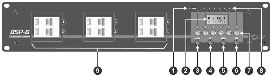
- DMX LED: Blinks when a DMX signal is detected.
- LCD DISPLAY: monitors the current output states of the channels and helps the user with the setup of the different menus.
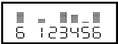
In normal working condition the display shows the output states of the channels (see picture): The screen shows 6 channels. Above each channel there's a bar indicating the dimming level of that channel. The first digit shows the name of the channel that has been last modified. (in the picture the dimming value of channel 6 was the last modified)
- MENU Button: Used to access the different setup menus. See "Setup menus" for more information.
- UP Button: Used to scroll the menus or to increase the values.
- DOWN Button: Used to scroll the menus or to decrease the values
- ESC Button: Used to go one step back in the menu level or to leave the menu system.
- CHANNEL BUTTONS: The DSP6 can work without a controller for the input signals. This is a good option if you just need a certain output level on each channel over a long time (shops, exhibition booths, pubs etc...) Just press and hold the channel button of the channel you want to edit. While you keep the channel button pressed you can use the "up/down" buttons to change the output level of that channel.
-
CHANNEL INDICATORS: In addition to the LCD display these leds show the output condition of the channels.
-
CIRCUIT BREAKERS: In case of a short circuit these circuit breakers switch off to protect the output stages of the DSP6. After inspection of the installation you can switch them back on. In normal working condition these circuit breakers are always switched on.
REAR PANEL
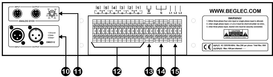
10.DMX INPUT: male XLR-connector used to connect the DSP6 to a DMX controller or any other DMX unit in the chain.
DMX OUTPUT: female XLR-connector used to connect the DSP6 to the next unit in the DMX chain.
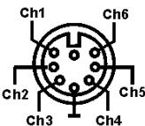
11.ANALOGUE INPUTS: 8pin DIN connector used for the analogue 0 10Vdc inputs. Refer to the picture on the right for the pinning of the connector.
Attention: The analogue input only works when the "DMX fail" option is set to "Analog" and no DMX-signal is connected to the DSP6 (DMX led is off)
12.CHANNEL OUTPUTS: Each of the 6 channels have 2 output ch3 ch4 wires. While connecting please pay attention to the "L" and "N" indications on the back panel.
13.EARTH WIRE CONNECTIONS: Make sure to earth the DSP6 properly!
14. NEUTRAL INPUT WIRES: Neutral input wires. These 3 connectors are linked together on the inside of the DSP6.
15.PHASE INPUTS: The DSP6 can be connected in single phase or 3phase. Refer to the next chapter for proper connection.
CONNECTIONS
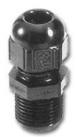
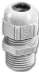
This unit may only be installed by qualified personal, following the rules for electrical installations in your country! After installation always put the metal covers back in place and make sure to use proper cable entry glands (see picture) to protect the wires from unwanted traction and friction.
-
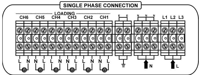
SINGLE PHASE INSTALLATION (2 wires “L”+“N”+ earth wire “E”:
-
Since you have only 1 phase wire (L) you must make bridges between the L1/L2/L3 inputs and connect the phase wire to these inputs.
- Connect the neutral (N) to the N-input.
- Connect the loads to the output channels (2 connections, named "L" and "N") All connections named "N" are linked inside the DSP6.
- Don't forget to connect the earth connection properly!
-
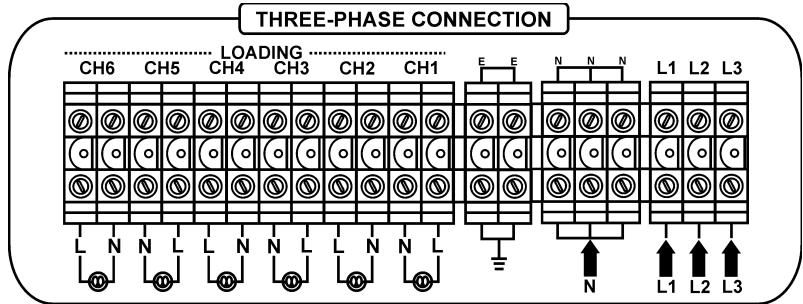
THREE PHASE INSTALLATION (4wires “L1+L2+L3+N” + earth wire “E”:
-
Since you have 3 phase wires you can connect these directly to the corresponding L1/L2/L3 inputs.
- Connect the neutral (N) to the N-input.
- Connect the loads to the output channels (2 connections, named "L" and "N") All connections named "N" are linked inside the DSP6.
- Don't forget to connect the earth connection properly!
SETUP MENUS
Please refer to the overview below to fully understand the menu structure of the DSP6:
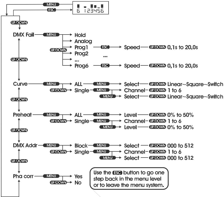
You can clearly see which buttons to push to select a certain function. In most cases the DSP6 is in normal working condition (display shows channel output condition). Push the "menu" button to enter the setup menus. With the "up/down" buttons you can scroll through the 5 available menus. With the "esc" button you can go one step back in the menu. After +/-30 sec the DSP6 returns automatically to the normal working mode.
In the next chapter you can read more about each function.
MENU ITEMS
- DMX FAIL:
The DSP6 works with analog 0/10V or digital DMX-512 input signals. DMX-signals have priority to the analog inputs. This means that you can only use the analog inputs when no DMX-signal is detected. When the DMX-signal is not present you have 3 options:
Hold:
In case of DMX-fail the DSP6 keeps the last scene on the outputs.
- Press "menu" and "up/down" until the display shows "Dmx fail".
- Press "menu" again: the display shows one of the 3 options.
- Press "up/down" until the display shows "Hold"
- Press "esc" to store this option and leave the menu.
- Analog:
In case of DMX-fail the DSP6 goes in analog 0/10V mode.
- Press "menu" and "up/down" until the display shows "Dmx fail".
- Press "menu" again: the display shows one of the 3 options.
- Press "up/down" until the display shows "Analog"
- Press "esc" to store this option and leave the menu.
- Prog 01 ... Prog 12:
In case of DMX-fail the DSP6 shows one of the 12 built-in patterns.
- Press "menu" and "up/down" until the display shows "Dmx fail".
- Press "menu" again: the display shows one of the 3 options.
- Press "up/down" until the display shows the desired program (Prog 01 ... 12)
- Press "esc" and "up/down" buttons to select the proper speed
- Press "esc" to store the selected speed and leave the menu.
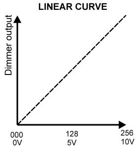
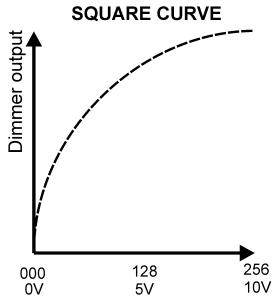
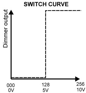
CURVE:
With the DSP6 you can select a different working mode (curve) for each individual channel. This is a nice feature if you need to switch light effects on/off while at the same time you have to dim lamps. 3 Curves are available:
- Select a curve for all channels:
- Press "menu" and "up/down" until the display shows "Curve".
- Press "menu" again: the display shows one of the 2 options.
- Press "up/down" until the display shows "All"
-
Press "menu" to select this option.
-
Press "up/down" to select one of the 3 curves
- Press "esc" to store the selected curve and leave the menu.
- Select a curve for individual channels:
- Press "menu" and "up/down" until the display shows "Curve".
- Press "menu" again: the display shows one of the 2 options.
- Press "up/down" until the display shows "Single"
- Press "menu" to select this option: the display shows the channel number on the first row and the curve on the second row.
- Press "menu" to toggle between both rows.
- Press "up/down" to set the desired curves and channel numbers until all channels are set.
- Press "esc" to store the selected curves and leave the menu.
- PREHEAT:
On the DSP6 you can set a preheat level up to 50% for all channels in one time or for each channel separately. While the preheat function keeps the lamp filament at a certain temperature, the turn on current of the lamp is much lower. This extends the lamp life considerably in many cases.
- Preheat on all channels:
- Press "menu" and "up/down" until the display shows "Preheat".
- Press "menu" again: the display shows one of the 2 options.
- Press "up/down" until the display shows "All"
- Press "menu" to select this option.
- Press "up/down" to set the desired overall level.
- Press "esc" to store the selected level and leave the menu.
- Preheat on individual channels:
- Press "menu" and "up/down" until the display shows "Preheat".
- Press "menu" again: the display shows one of the 2 options.
- Press "up/down" until the display shows "Single"
- Press "menu" to select this option: the display shows the channel number on the first row and the preheat level on the second row.
- Press "menu" to toggle between both rows.
- Press "up/down" to set the desired preheat levels and channel numbers until all channels are set.
- Press "esc" to store the selected preheat levels and leave the menu.
- DMX ADDRESSING:
On the DSP6 you can set the DMX start address for the complete unit or for each channel separately. Due to this "soft patch" option DMX addressing becomes extremely flexible.
- Setting the start address for the complete unit:
- Press "menu" and "up/down" until the display shows "Dmx addr"
- Press "menu" again: the display shows one of the 2 options.
- Press "up/down" until the display shows "Block"
- Press "menu" to select this option.
- Press "up/down" to set the desired start address for the DSP6.
- Press "esc" to store the selected level and leave the menu.
- Setting the start address for individual channels:
- Press "menu" and "up/down" until the display shows "Dmx addr"
- Press "menu" again: the display shows one of the 2 options.
- Press "up/down" until the display shows "Single"
- Press "menu" to select this option: the display shows the channel number on the first row and the DMX address on the second row.
- Press "menu" to toggle between both rows.
- Press "up/down" to set the desired DMX addresses and channel numbers until all channels are set.
- Press "esc" to store the selected DMX addresses and leave the menu.
PHASE CORRECTION:
To be able to produce perfectly linear curves the DSP6 has phase correction on board. Normally this option should always be switched on. However some control desks have built-in phase correction that can't be switched off. In these cases the phase correction of the DSP6 can be switched off.
- Switching phase correction on/off:
- Press "menu" and "up/down" until the display shows "Pha corr"
- Press "menu" again: the display shows one of the 2 options (on/off)
- Press "up/down" until the display shows the desired option.
- Press "esc" to store the selected option and leave the menu.
SPECIFICATIONS
Power Input:
Single Phase 230Vac 50 60Hz (2 wires)
Three Phase 230Vac 50 60Hz (4 wires)
Power outputs:
Max. 6x 10A (max.10A per channel)
DMX-512 in/out:
in: male 3pin XLR ~ out: female 3pin XLR
Analog input:
DIN 8pin connector: 0 10Vdc
Size (WxHxD):
483× 88× 420mm
Weight:
9kg
Every information is subject to change without prior notice
MODE D'EMPLOI
in: XLR male a 3 broches
ENKELE FASE AANSLUITING (2 draden “L + N” + aardleiding “E”)
out: female 3pin XLR
Analoger Input: DIN 8pin Verbinder: 0 10Vdc
MaBe (LxHxB): 483 x 88 x 420mm
Gewicht: 9kg