
D 880 - Headphones AKG - Free user manual and instructions
Find the device manual for free D 880 AKG in PDF.
| Product type | Dynamic microphone |
| Brand | AKG |
| Model | D 880 |
| Polar pattern | Supercardioid |
| Frequency response | 60 Hz - 20 kHz |
| Sensitivity | 2.2 mV/Pa (-53 dBV) |
| Max. SPL | 147 dB SPL (1% distortion) / 156 dB SPL (3% distortion) |
| Equivalent noise level | 22 dB-A |
| Electrical impedance | ≤ 600 ohms |
| Recommended load impedance | ≥ 2000 ohms |
| Connector | XLR 3-pin (balanced) |
| Power supply | None in wired mode; requires 9V battery for TM40 transmitter module (optional) |
| Dimensions (diameter x length) | 50 mm x 181 mm |
| Net / gross weight | 290 g / 650 g |
| Housing material | Zinc die-cast and aluminum, matte black finish |
| Grille | Spring steel, unbreakable |
| Main features | Vocal microphone, supercardioid polar pattern, integrated pop filter, Doubleflex anti-noise suspension, interchangeable TM40 transmitter module (optional) |
| Included accessories | SA 61 microphone clip, carrying case, XLR module (depending on version) |
| Maintenance | Clean the housing with a damp cloth; wash the windscreen with soapy water and let it dry overnight |
| Spare parts and repairability | W880 windscreen, H30 suspension, SA26 clip, MK 9/10 cable, TM40 transmitter module. Removable XLR module and screw-off grille for maintenance |
| Safety | Check the compliance and grounding of the connected device |
Frequently Asked Questions - D 880 AKG
User questions about D 880 AKG
0 question about this device. Answer the ones you know or ask your own.
Ask a new question about this device
Download the instructions for your Headphones in PDF format for free! Find your manual D 880 - AKG and take your electronic device back in hand. On this page are published all the documents necessary for the use of your device. D 880 by AKG.
USER MANUAL D 880 AKG
D 880M
D 880^M S
D 880^M/TM 40

User Instructions . p. 12
Please read the manual before using the equipment!
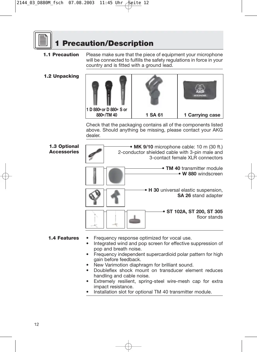
Please make sure that the piece of equipment your microphone will be connected to fulfills the safety regulations in force in your country and is fitted with a ground lead.
1.2 Unpacking
| 1 D 880M or D 880M S or 880M/TM 40 | 1 SA 61 | 1 Carrying case |
Check that the packaging contains all of the components listed above. Should anything be missing, please contact your AKG dealer.
1.3 Optional Accessories
- MK 9/10 microphone cable: 10m (30 ft.) 2-conductor shielded cable with 3-pin male and 3-contact female XLR connectors
TM 40 transmitter module W880 windscreen
H 30 universal elastic suspension, SA 26 stand adapter
ST102A,ST200,ST305 floor stands
1.4 Features
Frequency response optimized for vocal use.
- Integrated wind and pop screen for effective suppression of pop and breath noise.
- Frequency independent supercardioid polar pattern for high gain before feedback.
- New Varimotion diaphragm for brilliant sound.
- Doubleflex shock mount on transducer element reduces handling and cable noise.
- Extremely resilient, spring-steel wire-mesh cap for extra impact resistance.
- Installation slot for optional TM 40 transmitter module.
The AKG D 880^M is a supercardioid dynamic microphone. It has been designed specifically as a vocal microphone for rough onstage use. The wide frequency response of the D 880^M slightly favors the midfrequency and treble regions to ensure good intelligibility of speech. The term "supercardioid polar response" means that the D 880^M is most sensitive to sound arriving from in front of it, less sensitive to sound arriving from the sides and rear. This pickup pattern is virtually the same for all frequencies or, in other words, from the lowest to the highest notes ("frequency independent").
The Doubleflex shock mount on the transducer minimizes handling and cable noise. An integrated windscreen reduces pop, wind, and breath noise to a minimum.
A rugged front grill made of spring-steel wire mesh that is extremely resistant to deformation and a sturdy zinc alloy diecast body effectively protect the microphone and transducer element from damage on stage and on the road.
The D 880M features a removable connection module with a 3-pin XLR connector. You can connect the microphone to both balanced and unbalanced mixer or amplifier inputs.
1.5 D 880M, D 880TM 40
You can easily convert the microphone into a wireless microphone. All you need to do is remove the XLR connector module and replace it with an optional TM 40 transmitter module.
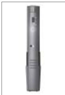
Fig. 1: Optional TM 40 transmitter module.
1.6 D 880M S
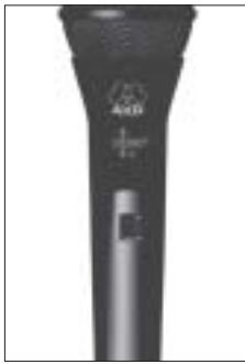
The D 880^M S has the same mechanical, electrical, and acoustic characteristics as the D 880^M and features an XLR connector module with a noiseless on/off switch. The switch is recessed to prevent the microphone being switched off unintentionally.

Fig. 2: On/off switch on D 880^M S.
2 Interfacing
2.1 Output Circuit
The microphone provides a balanced output on a 3-pin male XLR connector:
Pin 1: ground
Pin 2: hot
Pin 3: return
You can connect the microphone either to a balanced or an unbalanced microphone input.
2.2 Connecting the Microphone to a Balanced Input
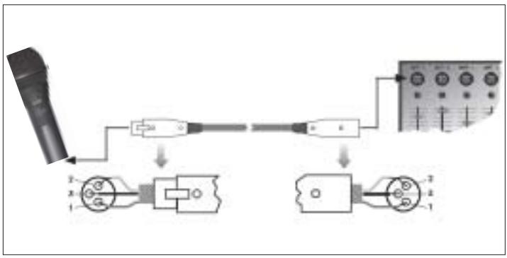
Fig. 3: Using a balanced connecting cable.
Refer to fig. 3.
- Use a commercial XLR cable such as the optional MK 9/10 from AKG.
The length of these cables does not affect audio quality. - Plug the female XLR connector on the microphone cable into the male XLR connector on the microphone.
- Plug the other connector on the microphone cable into the desired microphone input socket on your mixer or amplifier.
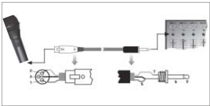
2.3 Connecting the Microphone to an Unbalanced Input
- To connect the microphone to an unbalanced microphone input (1/4" jack), use a cable with a female XLR connector and a 1/4" TS jack plug. These cables are available at music stores.
Please note that unbalanced cables may pick up interference from stray magnetic fields near power or lighting cables, electric motors, etc. like an antenna. This may cause hum or similar noise when you use a cable that is longer than 16 feet (5 m). - Plug the female XLR connector on the microphone cable into the male XLR connector on the microphone.
- Plug the other connector on the microphone cable into the desired microphone input jack on your mixer or amplifier.
The optional TM 40 transmitter module allows you to convert your microphone into a wireless microphone that you can use with any WMS 40 Series receiver from AKG.
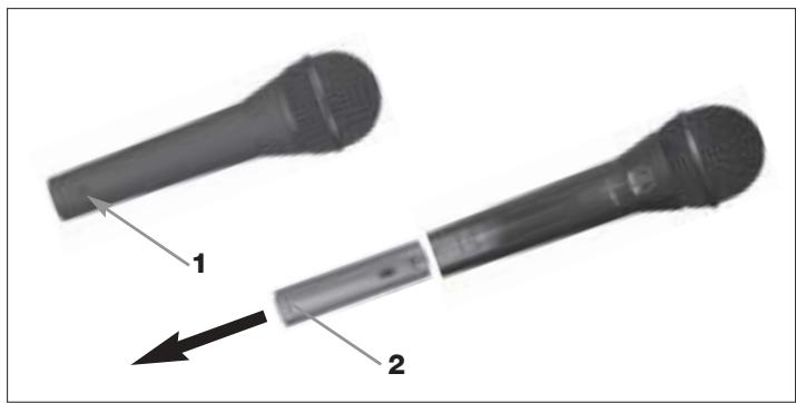
Fig. 4: Using an unbalanced cable.
- Open the fixing screw (1).
- Pull the XLR connector module (2) out of the microphone body.
Refer to fig. 4.
2.4 Optional TM 40 Transmitter Module
Start by removing the XLR connector module:
Fig. 5: Removing the XLR connector module.
Refer to fig. 5.
- To avoid losing the fixing screw (1), screw it into the threaded hole (3) in the XLR connector module.
Install the transmitter module:
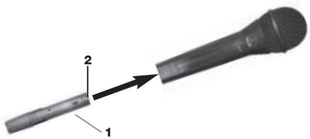
Fig. 6: Installing the transmitter module.
Refer to fig. 6.
- Do not forget to check the condition of the battery inside the transmitter module. If the battery is dead or there is no battery inside the transmitter module, insert a new battery.
- Hold the transmitter module (1) to align the contacts (2) with the microphone.
- Slide the transmitter module (1) into the microphone body to the point that the transmitter module (1) will lock with an audible click.
As the transmitter module locks in place, the electrical connections to the microphone are made automatically.
Note:
For details on inserting, replacing, and testing the battery as well as setting up and operating the transmitter module refer to the TM 40 transmitter module manual.
Replacing the transmitter module with the XLR connector module:
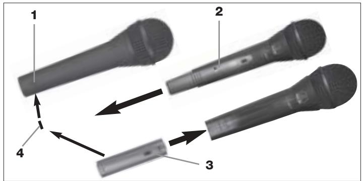
Fig. 7: Removing the transmitter module.
Refer to fig. 7.
- Insert a ball point pen, small screwdriver, or similar pointed object into the opening (1) in the microphone body and press inward.
The transmitter module (2) will unlock and slide out of the microphone body for about 0.1 inch.
- Pull the transmitter module (2) out of the microphone.
- Unscrew the fixing screw (4) from the XLR connector module (3).
- Slide the XLR connector module (3) into the microphone body to the stop.
- To fix the XLR connector module (3), screw the fixing screw (4) down firmly.
Refer to fig. 7.
Alternatively, you can remove the transmitter module simply by pulling it out of the microphone body with just enough force to unlock it. Make sure not to grasp the transmitter module by the battery compartment. (If you did, you would only open the battery compartment.)
Note:
3 Using Your Microphone

A handheld vocal microphone provides many ways of shaping the sound of your voice as it is heard over the sound system.
The following sections contain useful hints on how to use your microphone for best results.
The following sections apply to both the hardwire D 880M/ D 880M S and either version with an optional TM 40 transmitter module installed.
3.1 Introduction
Basically, your voice will sound the bigger and mellower, the closer you hold the microphone to your lips. Moving away from the microphone will produce a more reverberant, more distant sound as the microphone will pick more of the room's reverberation.
You can use this effect to make your voice sound aggressive, neutral, insinuating, etc. simply by changing your working distance.
Proximity effect is a more or less dramatic boost of low frequencies that occurs when you sing into the microphone from less than 2 inches. It gives more "body" to your voice and an intimate, bass-heavy sound.
3.2 Working Distance and Proximity Effect
3.3 Angle of Incidence

Fig. 8: Typical microphone position.
Sing to one side of the microphone or above and across the microphone's top. This provides a well-balanced, natural sound.
If you sing directly into the microphone, it will not only pick up excessive breath noise but also overemphasize "sss", "sh", "tch", "p", and "t" sounds.
3.4 Feedback
Refer to fig. 9.
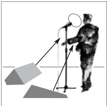
Fig. 9: Microphone placement for maximum gain before feedback.
Feedback is the result of part of the sound projected by a speaker being picked up by a microphone, fed to the amplifier, and projected again by the speaker. Above a specific volume or "system gain" setting called the feedback threshold, the signal starts being regenerated indefinitely, making the sound system howl and the sound engineer desperately dive for the mas
ter fader to reduce the volume and stop the howling.
To increase usable gain before feedback, the microphone has a supercardioid polar pattern. This means that the microphone is most sensitive to sounds arriving from in front of it (your voice) while picking up much less of sounds arriving from the sides or rear (from monitor speakers for instance).main ("FOH") speakers in front of the microphones (along the front edge of the stage).
If you use monitor speakers, be sure never to point any microphone directly at the monitors, or at the FOH speakers.
Feedback may also be triggered by resonances depending on the acoustics of the room or hall. With resonances at low frequencies, proximity effect may cause feedback. In this case, it is often enough to move away from the microphone a little to stop the feedback.
3 Using Your Microphone

- Never let more than two persons share a microphone.
- Ask your backing vocalists never to sing more than 35 degrees off the microphone axis.
The microphone is very insensitive to off-axis sounds. If the two vocalists were to sing into the microphone from a wider angle than 35 degrees,

you may end up bringing up the fader of the microphone channel far enough to create a feedback problem.
3.5 Backing Vocals
4 Cleaning

Fig. 10: Two vocalists sharing a microphone.
To clean the surface of the microphone body, use a soft cloth moistened with water.
- Unscrew the front grill from the microphone CCW.
- Remove the windscreen from the from grill and wash the windscreen in soap suds.
- Allow the windscreen to dry overnight.
- Replace the windscreen in the front grill and screw the front grill on the microphone CW.
4.1 Microphone Body
4.2 Internal Windscreen
5 Troubleshooting
| Problem | Possible Cause | Remedy |
| No sound. | 1. Power to mixer and/or amplifier is off. 2. Channel or master fader on mixer, or volume control on amplifier is at zero. 3. Microphone is not connected to mixer or amplifier. 4. Cable connectors are seated loosely. 5. Cable is defective. 6. Transmitter module is off or muted. 7. No/dead battery in transmitter module. 8. Receiver is off or not connected to mixer. | 1. Switch power to mixer or amplifier on. 2. Set channel or master fader on mixer or volume control on amplifier to desired level. 3. Connect microphone to mixer or amplifier. 4. Check cable connectors for secure seat. 5. Check cable and replace if damaged. 6. Switch transmitter module on. 7. Insert new/fully charged battery. 8. Switch receiver on or connect to mixer. |
| Distortion. | 1. Gain control on mixer or transmitter module not set correctly. 2. Mixer input sensitivity too high. | 1. Set gain control to stop distortion. 2. Insert 10 dB preattenuation pad between microphone cable and input. |
| Microphone sound becomes duller by and by. | • Internal or external windscreen attenuates high frequencies when soiled. | • Clean internal or external windscreen. |
| Polar pattern: | supercardioid |
| Frequency range: | 60 to 20,000 Hz |
| Sensitivity at 1000 Hz: | 2.2 mV/Pa (-53 dBV re 1 V/Pa) |
| Max. SPL for 1 % / 3 % THD: | 147 dB SPL / 156 dB SPL |
| Equivalent noise level: | 22 dB-A (DIN 45412) |
| Electrical impedance at 1000 Hz: | ≤600 ohms |
| Recommended load impedance: | ≥2000 ohms |
| Connector: | 3-pin XLR |
| Finish: | matte black |
| Size: | length: 181 mm (7.1 in.)dia.: 50 mm (2 in.) |
| Net/shipping weight: | 290 g (10.2 oz.) / 650 g (1.4 lbs.) |
This product conforms to EN 50 082-1 provided it is connected to equipment with a CE sign.

Frequency Response
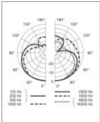
Polar Diagram
broche 2 = point chaud
broche 3 = pointfroid
H A Harman International Company
AKG Acoustics GmbH
Bodenesestraße 228, D-81243 München/GERMANY, Tel: (+49 89) 87 16-0, Fax: (+49 89) 87 16-200, www.akg-acoustics.de, e-mail: info@akg-acoustics.de, Hotline: (+49 89) 87 16-22 50, hotline@akg.com
AKG ACOUSTICS, U.S.
914 Airpark Center Drive, Nashville, TN 37217, U.S.A., Tel: (+1 615) 620-3800, Fax: (+1 615) 620-3875, www.akgusa.com, e-mail: akgusa@harman.com
For other products and distributors worldwide see our website: www.akg.com