
PT 40 PRO - Wireless Microphone System AKG - Free user manual and instructions
Find the device manual for free PT 40 PRO AKG in PDF.

| Product type | Bodypack transmitter for wireless microphone system |
| Brand | AKG |
| Model | PT 40 PRO |
| Frequency range | 660 - 865 MHz (UHF, crystal-controlled fixed) |
| Modulation | FM |
| Audio bandwidth | 40 - 20,000 Hz |
| Frequency stability | ±15 kHz (-10°C to +50°C) |
| Nominal deviation | 15 kHz |
| Distortion factor (1 kHz) | typ. 0.8% |
| Compander | Yes |
| Signal-to-noise ratio | typ. 75 dB(A) |
| RF output power | 10 mW |
| Power consumption | typ. 70 mA |
| Power supply | 1 AA 1.5 V battery (LR6) |
| Battery life | typ. 30 h (2200 mAh battery) |
| Audio input level | 25 - 750 mV/1 kHz, adjustable |
| Input impedance | 1 MΩ |
| Microphone capsule power | 4 V / 4.7 kΩ (pin 3) |
| Input connector | 3-pin mini XLR |
| Antenna | Integrated flexible antenna |
| Functions | ON/MUTE/OFF, GAIN adjustment, LED indicator (green/red) |
| Dimensions (W x H x D) | 60 x 74 x 30 mm |
| Net weight | 60 g |
| Included accessories | AA battery, label sheet, appendix (Manual Supplement) |
| Cleaning | Soft cloth slightly damp, no harsh cleaners |
| Safety | Do not open, avoid moisture and heat sources |
Frequently Asked Questions - PT 40 PRO AKG
User questions about PT 40 PRO AKG
0 question about this device. Answer the ones you know or ask your own.
Ask a new question about this device
Download the instructions for your Wireless Microphone System in PDF format for free! Find your manual PT 40 PRO - AKG and take your electronic device back in hand. On this page are published all the documents necessary for the use of your device. PT 40 PRO by AKG.
USER MANUAL PT 40 PRO AKG
Please read the manual before using the equipment!
MODE D'EMPLOI p.27
1 Safety and Environment 16
1.1 Safety 16
1.2 Environment 16
2 Description. 17
2.1 Introduction 17
2.2 Packing List 17
2.3 Optional Accessories 17
2.4 PT 40 PRO Bodypack Transmitter 17
2.4.1 Controls 17
2.5 PT 40 FLEXX Bodypack Transmitter 18
2.4.1 Controls 18
2.6 Microphones, Guitar Cable 19
3 Setting Up 20
3.1 Inserting and Testing Batteries (PT 40 PRO and PT 40 FLEXX) 20
3.2 Connecting a Microphone/Instrument (PT 40 PRO) 20
3.3 Connecting a Microphone/Instrument (PT 40 FLEXX) 21
3.4 Inserting a Label (PT 40 PRO and PT 40 FLEXX) 22
3.5 Before the Soundcheck (PT 40 PRO and PT 40 FLEXX) 22
3.6 Multichannel Systems (PT 40 FLEXX + SR 40 FLEXX) 22
3.7 Changing Carrier Frequencies (PT 40 FLEXX + SR 40 FLEXX) 22
4 Microphone Technique 23
4.1 CK 55 L Lavalier Microphone 23
4.2 C 555 L Head-worn Microphone 23
4.2.1 Positioning the Microphone 23
4.2.2 Windscreen 23
4.2.3 Moisture Shield 24
5 Cleaning 24
6 Troubleshooting 25
7 Specifications 26
Fig. 9 75
FCC Statement
This equipment has been tested and found to comply with the limits for a Class B digital device, pursuant to Part 74 of the FCC Rules. These limits are designed to provide reasonable protection against harmful interference in a residential installation. This equipment generates, uses, and can radiate radio frequency energy and, if not installed and used in accordance with the instructions, may cause harmful interference to radio communications. However, there is no guarantee that interference will not occur in a particular installation. If this equipment does cause harmful interference to radio or television reception, which can be determined by turning the equipment off and on, the user is encouraged to try to correct the interference by one or more of the following measures:
Reorient or relocate the receiving antenna.
- Increase the separation between the equipment and the receiver.
Connect the equipment into an outlet on a circuit different from that to which the receiver is connected.
Consult the dealer or an experienced radio/TV technician for help.
Shielded cables and I/O cords must be used for this equipment to comply with the relevant FCC regulations.
Changes or modifications not expressly approved in writing by AKG Acoustics may void the user's authority to operate this equipment.
This device complies with Part 15 of the FCC Rules. Operation is subject to the following two conditions: (1) this device may not cause harmful interference, and (2) this device must accept any interference received, including interference that may cause undesired operation.

PT 40 PRO/FLEXX

1.1 Sicherheit
1 Safety and Environment
1 PT 40 PRO or PT 40 FLEXX bodypack transmitter
1 AA size battery
1 set of lettering labels
1 MKG L guitar cable
1 Manual Supplement sheet
- Check that the packaging contains all of the items listed for your system. Should any of these items be missing, please contact your AKG dealer.
- For optional accessories, refer to the current AKG catalog or folder, or visit www.akg.com. Your dealer will be glad to help.
2.2 Lieferumfang
2.3 Optionales Zubehör
2.4 PT 40 PRO
Bodypack Transmitter
You can use the PT 40 PRO bodypack transmitter with both dynamic microphones and condenser microphones operating on a supply voltage of approx. 4 V. You may also connect an electric guitar, electric bass, or remote keyboard.
The PT 40 PRO operates on a single fixed, quartz stabilized frequency in the 660 MHz to 865 MHz UHF carrier frequency range.
1 On/off switch: This slide switch provides three positions indicated in the display window:
ON: Power to the transmitter is on.
MUTE: The signal delivered by the microphone element is muted while power and the RF carrier frequency remain on.
OFF: Power to the transmitter is off.
2 Status LED: Indicates the transmitter's operating status.
LED lit green: Battery is OK.
LED lit red: From the moment the LED changes to red, the battery capacity will provide a maximum of two operating hours. We recommend replacing the battery with a new one as soon as possible.
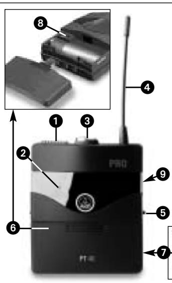
2.4.1 Controls
Fig. 1: Controls on PT 40 bodypack transmitter.
Note:
- If you use a rechargeable battery, the LED will change to red 15 minutes before the battery will be dead!
3 Audio input: 3-pin mini XLR connector with both mic and line level pins that automatically match the connector pinout of the recommended AKG microphones or optional MKG L guitar cable.
4 Antenna: Permanently connected, flexible antenna.
5 Belt clip for fixing the transmitter to your belt.
6 Battery compartment lid with integrated screwdriver.

2 Description
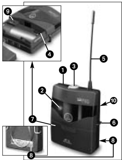
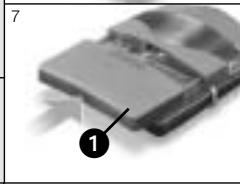
7 Viewing window: The viewing window lets you check if there is a dry or rechargeable battery inside the battery compartment. You can also insert a white lettering strip (supplied) or a color code strip (optional) into the viewing window.
8 GAIN: This rotary control inside the battery compartment allows you to match the body-pack transmitter input gain to the microphone or instrument you connected to the transmitter.
9 Carrier frequency label: The label on the transmitter rear panel indicates the carrier frequency, color code (receiver channels with the same carrier frequency are marked with the same color), and approval marks of your transmitter. Refer to the Manual Supplement sheet for a color code table.
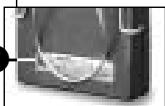
2.5 PT 40 FLEXX Bodypack Transmitter
Operating in the 660 MHz to 865 MHz UHF range, the PT 40 FLEXX provides three selectable, quartz stabilized carrier frequencies within the 3-MHz-wide frequency band for which you ordered your WMS 40 FLEXX.
You can use the PT 40 FLEXX bodypack transmitter with both dynamic microphones and condenser microphones designed for a supply voltage of approx. 4 V. You may also connect an electric guitar, electric bass, or remote keyboard.
2.5.1 Controls
1 On/off switch: This slide switch provides three positions:
ON: Power to the transmitter is on.
MUTE: The signal delivered by the microphone element is muted while power and the RF carrier frequency remain on.
OFF: Power to the transmitter is off.
2 Status LED: Indicates the transmitter's operating status.
LED lit green: Battery is OK.
LED lit red: From the moment the LED changes to red, the battery capacity will provide a maximum of two operating hours. We recommend replacing the battery with a new one as soon as possible.
Note:
If you use a rechargeable battery, the LED will change to red 15 minutes before the battery will be dead!
3 Audio input: 3-pin mini XLR connector with both mic and line level pins that automatically match the connector pinout of the recommended AKG microphones or MKG L guitar cable.
4 Frequency selector: This slide switch tunes the transmitter to one of three different carrier frequencies within the transmitter's carrier frequency band.
5 Antenna: Permanently connected, flexible antenna.
6 Belt clip for fixing the transmitter to your belt.
7 Battery compartment lid with integrated screwdriver.
8 Viewing window: The viewing window lets you check if there is a dry or rechargeable battery inside the battery compartment. You can also place a white lettering strip (supplied) or a color code strip (optional) behind the viewing window.
2 Description

9 GAIN: This rotary control inside the battery compartment allows you to match the body-pack transmitter input gain to the microphone or instrument you connected to the transmitter.
10 Carrier frequency label: The label on the transmitter rear panel indicates the name of the carrier frequency band and the three carrier frequencies of your transmitter. Refer to the Manual Supplement sheet for a color code table.
The PT 40 PRO and PT 40 FLEXX bodypack transmitters have been designed for use with the following AKG microphones:
CK55L,C417L,C520L,C555L
C 516 ML, C 518 ML. C 519 ML
If you wish to connect other microphones from AKG or other manufacturers to your bodypack, please note that you may have to rewire the existing connector on your microphone or replace it with a 3-pin mini XLR connector.
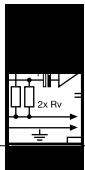
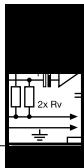
Audio input pinout:
Pin 1: shield
Pin 2:audio inphase (+)
Pin 3: supply voltage
A 4-V positive supply voltage for condenser microphones is available on pin 3.
- The MKG L guitar cable from AKG lets you connect an electric guitar, electric bass, or remote keyboard to the bodypack transmitter. The MKG L guitar cable is included in the Instrumental Set SINGLE, Instrumental Set DUAL, and Instrumental Set FLEXX. It is also available separately as an accessory.
- Please note that AKG cannot guarantee that the PT 40 FLEXX bodypack transmitter will work perfectly with products from other manufacturers, and any damage that may result from such use is not covered by the AKG warranty scheme.
2.6 Microphones, Guitar Cable

Important!

3.1 Inserting and Testing Batteries (PT 40 PRO and PT 40 FLEXX)
3 Setting Up
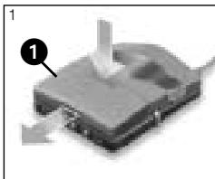
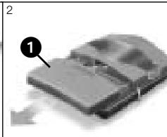
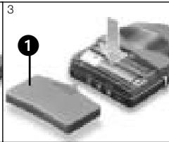
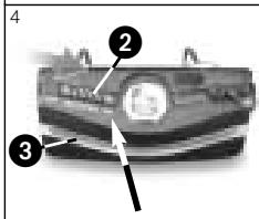
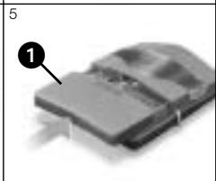
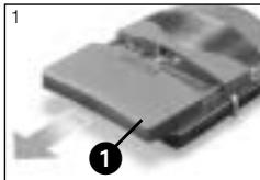
Fig. 3: Inserting the battery into the PT 40 PRO or PT 40 FLEXX bodypack transmitter.
Refer to fig. 3.
- Depress the snap hook on the battery compartment lid (1).
- Pull the battery compartment lid (1) off the transmitter in the direction of the arrow.
- Insert the supplied battery into the battery compartment conforming to the polarity marks. The transmitter will not function if you insert the battery the other way round.
- Set the on/off switch (2) to "ON" to switch power to the transmitter on. If the battery is in good condition, the status LED (3) will be lit green. If the status LED (3 is lit red, the battery will be dead within about two hours. Replace the battery with a new one as soon as possible.
Note:
- If you use a rechargeable battery, the LED will switch to red 15 minutes before the battery will be dead!
If the status LED (3) fails to illuminate the battery is dead. Insert a new battery.
- To close the battery compartment, slide the battery compartment lid (1) onto the battery compartment from below to the point that the snap hook will engage.
3.2 Connecting a Microphone/Instrument (PT 40 PRO)
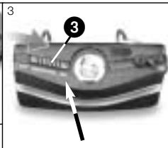
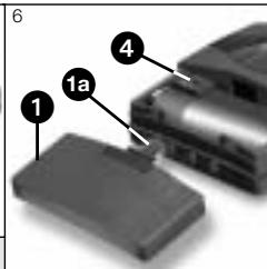
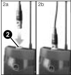
Fig. 4: Connecting a microphone or instrument.
Refer to fig. 4.

- Remove the battery compartment lid (1).
- a) Plug the mini XLR connector on the cable of your microphone into the audio input socket (2) on the bodypack transmitter.
b) Plug the jack plug on the MKG L guitar cable into the output jack on your instrument and the mini XLR connector on the guitar cable into the audio input socket (2) on the bodypack transmitter.
3 Setting Up
- Set the on/off switch (3) to "ON" to switch power to the bodypack transmitter on.
- Switch power to the receiver on.
- a) Talk or sing into the microphone.
b) Play your instrument. - Use the screwdriver (1a) integrated in the battery compartment lid (1) to set the GAIN control (4) to a position where the AF CLIP LED on the receiver will flash occasionally.
- Replace the battery compartment lid (1) on the transmitter.
See also section 4.
3.3 Connecting a Microphone/Instrument (PT 40 FLEXX)
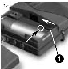
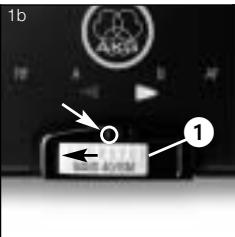
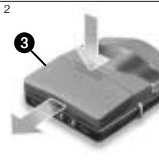
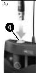
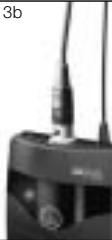
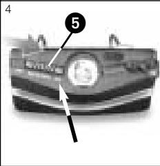
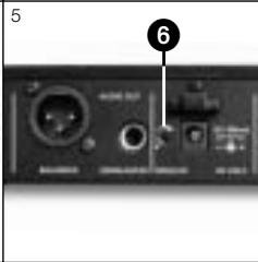

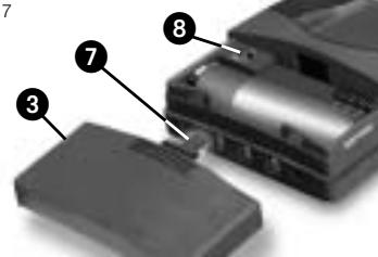
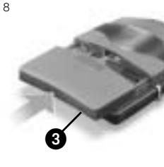
Fig. 5: Connecting a microphone or instrument to the PT 40 FLEXX bodypack.
- Set the frequency selector (1) on the transmitter and the frequency selector on the receiver to the same positions (1 - 1, 2 - 2, or 3 - 3).
If the transmitter and receiver are tuned to different frequencies, no signal will be received!
- Remove the battery compartment lid (1).
-
a) Plug the mini XLR connector on the cable of your microphone into the audio input socket (2) on the bodypack transmitter.
b) Plug the jack plug on the MKG L guitar cable into the output jack on your instrument and the mini XLR connector on the guitar cable into the audio input socket (2) on the bodypack transmitter. -
Set the on/off switch (3) to "ON" to switch power to the bodypack transmitter on.
- Set the SQUELCH control (6) on the receiver to minimum and switch power to the receiver on.
- a) Talk or sing into the microphone.
b) Play your instrument. - Use the screwdriver (1a) integrated in the battery compartment lid (1) to set the GAIN control (4) to a position where the AF CLIP LED on the receiver will flash occasionally.
- Replace the battery compartment lid (1) on the transmitter.
Refer to fig. 5.
See also section 4.
3.4 Inserting a Label (PT 40 PRO and PT 40 FLEXX)
3.5 Before the Soundcheck (PT 40 PRO and PT 40 FLEXX)
Important!

channel Systems (X + SR 40 FLEXX)
Note:
Refer to fig. 9 on page 75.
Important!

3.7 Changing Carrier Frequencies (PT 40 FLEXX + SR 40 FLEXX)
3 Setting Up
- Remove the battery compartment lid.
- Remove a label from the supplied sheet.
- Letter the label as desired.
- Remove the battery and place the label on the viewing window.
-
Replace the battery and slide the compartment lid back in place on the transmitter.
-
Move the transmitter around the area where you will use the system to check the area for "dead spots", i.e., places where the field strength seems to drop and reception deteriorates.
If you find any dead spots, try to eliminate them by repositioning the receiver. If this does not help, avoid the dead spots. - The RF OK LED on the receiver going out means no signal is being received or the squelch is active.
Switch the transmitter on, move closer to the receiver, or set the squelch threshold to the point that the green RF OK LED will be lit. -
PT 40 FLEXX + SR 40 FLEXX: If the received signal is noisy, set the squelch threshold to a level where the noise will stop.
-
PT 40 FLEXX + SR 40 FLEXX: Never set the squelch threshold any higher than absolutely necessary. The higher the squelch threshold (-70dB = ., -100dB = .) , the lower the sensitivity of the receiver and thus the usable range between transmitter and receiver.
In each frequency band, the spacing between the three carrier frequencies of all WMS 40 FLEXX transmitters and receivers is wide enough for operating three radio channels simultaneously with no mutual interference.
For systems with up to nine channels you will need WMS 40 FLEXX kits in up to three different frequency bands. Please ask your dealer which frequency bands are suited for multichannel use and approved for the place where you will use the system. Perform steps 1 through 6 for each frequency band separately.
- Switch power to all transmitters and receivers off.
- Set the frequency selectors on the transmitter and receiver for channel 1 to "1".
- Set the frequency selectors on the transmitter and receiver for channel 2 to "2".
- Set the frequency selectors on the transmitter and receiver for channel 3 to "3".
- Set up the transmitter and receiver for channel 1.
-
Repeat steps 1 through 5 for channels 2 and 3.
-
Never operate two or more wireless channels on the same frequency at the same time and location. This would cause unwanted noise due to radio interference.
- Prior to changing a carrier frequency, be sure to switch the transmitter off. To activate the new carrier frequency, switch the transmitter back on.
4 Microphone Technique

4.1 CK 55 L
Lavalier Microphone
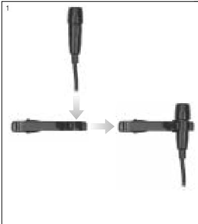
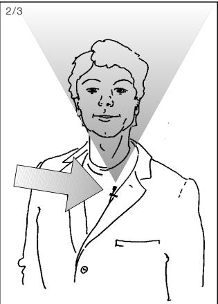
Fig. 7: Positioning the CK 55 L.
- Fix the microphone to the supplied lavalier clip or to the optional H 41/1 tiepin.
-
Clamp the microphone on your clothing as close as possible to the talker's mouth.
-
Remember that gain-before-feedback will be the higher the closer the microphone sits to the user's mouth!
-
Make sure to aim the microphone at the user's mouth.
-
Put the microphone on.
- Bend the gooseneck so that the microphone will sit to one side in front of the corner of your mouth.
Note:
- You can adjust the microphone to conform exactly to the shape of the user's head. For details, refer to the C 555 L instruction manual which you can download from www.akg.com.
Should you hear excessive pop noise ("p" and "t" sounds are overemphasized unnaturally), move the microphone capsule further away from your mouth (up or back).
If the microphone sounds "thin" or flat, move the microphone capsule closer to your mouth (refer to fig. 3).
Find the optimum position during the soundcheck.
If (for instance, in outdoor use) excessive wind or pop noise becomes audible, attach the supplied windscreen to the microphone.
- Slide the windscreen onto the microphone capsule.
- Pull the windscreen over the outer edge of the microphone capsule.
Fig. 6: Attaching the CK 55 L.
Refer to fig. 6.
Note:
4.2 C 555 L
Head-worn Microphone
4.2.1 Positioning
the Microphone
4.2.2 Windscreen

4.2.3 Moisture Shield
4 Microphone Technique
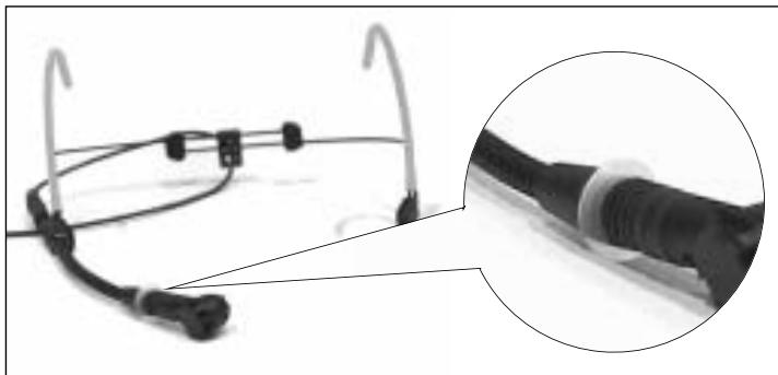
Fig. 8: Moisture shield on CK 55 L.
A special moisture shield on the microphone capsule makes it difficult for moisture and makeup to penetrate into the microphone. This barrier prevents the microphone sound entries from being clogged by perspiration or makeup, which would make the sound dull and reduce the sensitivity of the microphone. Therefore, never remove the moisture shield from the microphone!
In case the moisture shield is damaged or lost, the C 555 L head-worn microphone includes a replacement moisture shield.

5 Cleaning
- Use a soft cloth moistened with water to clean the surfaces of the PT40 PRO and PT 40 FLEXX transmitters.
6 Troubleshooting

| Problem | Possible Cause | Remedy |
| No sound. | 1. AC adapter is not connected to receiver and/or power outlet. 2. Receiver is OFF. 3. Receiver is not connected to mixer or amplifier. 4. VOLUME control on receiver is at zero. 5. Microphone or instrument is not connected to bodypack transmitter. 6. Transmitter is tuned to different frequency than receiver. 7. Transmitter on/off switch is at "OFF" or "MUTE". 8. Transmitter batteries are not inserted properly. 9. Transmitter batteries dead. 10. Transmitter is too far away from receiver or squelch threshold setting is too high. 11. Obstructions between transmitter and receiver. 12. Receiver is invisible from transmitter location. 13. Receiver is too close to metal objects. | 1. Connect AC adapter to receiver and/or power outlet. 2. Push ON/OFF switch to switch receiver ON. 3. Connect receiver output to mixer or amplifier input. 4. Turn up VOLUME control. 5. Connect microphone or instrument to audio input on bodypack. 6. Tune transmitter and receiver to same frequency. 7. Set transmitter on/off switch to "ON". 8. Insert batteries conforming to "+" and "-" marks. 9. Replace batteries. 10. Move closer to receiver or reduce squelch threshold setting. 11. Remove obstructions. 12. Avoid spots where you cannot see receiver. 13. Move receiver away from or remove interfering objects. |
| Noise, crackling, unwanted signals. | 1. Antenna location. 2. Interference from other wireless systems, TV, radio, CB radios, or defective electrical appliances or installations. | 1. Relocate receiver. 2. Switch off interference sources or defective appliances, use a WMS 40 SINGLE/DUAL tuned to a different frequency, or switch WMS 40 FLEXX to different frequency; have electrical installation checked. |
| Distortion. | 1. GAIN control is set too high or too low. 2. Interference from other wireless systems, TV, radio, CB radios, or defective electrical appliances or installations. | 1. Turn GAIN control down or up just enough to stop the distortion. 2. Switch off interference sources or defective appliances, use a WMS 40 SINGLE/DUAL tuned to a different frequency, or switch WMS 40 FLEXX to different frequency; have electrical installation checked. |
| Momentary loss of sound ("drops") at some locations within performance area. | • Antenna location. | • Relocate receiver. If dead spots persist, mark and avoid them. |
7 Specifications
PT 40 PRO and PT 40 FLEXX
| Carrier frequency range: | 660 to 865 MHz; PT 40 FLEXX: 3 selectable frequencies |
| Modulation: | FM |
| Audio bandwidth: | 40 Hz to 20 kHz; PT 40 FLEXX: 35 Hz to 20 kHz |
| Frequency stability(-10°C to +50°C): | ±15 kHz |
| Rated deviation: | 15 kHz |
| T.H.D. at 1 kHz: | typ. 0.8% |
| Compander: | Yes |
| Signal/noise ratio: | typ. 110 dB(A) |
| RF output: | 10 mW |
| Current consumption: | typ. 75 mA |
| Power requirement: | 1 x 1.5 V AA size battery (LR 6 to IEC 86-L) |
| Battery life: | typ. 31 hours (for 2200 mAh) |
| Audio input level for rated deviation: | 25 mV to 750 mV/1 kHz, adjustable |
| Input impedance: | 1 Mohm |
| Conenser mic power supply: | 4 V/4.7 kohms (pin 3) |
| Size: | 60 x 74 x 30 mm (2.4 x 2.9 x 1.2 in.) |
| Net weight: | 60 g (2.1 oz.) |
This product conforms to the standards listed in the Declaration of Conformity. To order a free copy of the Declaration of Conformity, visit http://www.akg.com or contact sales@akg.com.
Sommaire
Page
Fig.6: Fixer le microphone
Voir fig. 6.
Remarque :
For other products and distributors worldwide visit www.akg.com


ROHS OK

A Harman International Company
Technische Änderungen vorbehalten. Specifications subject to change without notice. Ces caractéristiques sont susceptibles de modifications. Ci riserviamo il diritto di effettuare modifiche tecniche. Nos reservamos el correcho de introduir modificaciones Tecnicas. Especificações sujeitas a mudanças sem uso prévio.
Printed in China (P.R.C.)
01/08/9100 U 12680

Brand : AKG
Model : PT 40 PRO
Category : Wireless Microphone System