HUB 4000 - Wireless Microphone AKG - Free user manual and instructions
Find the device manual for free HUB 4000 AKG in PDF.

| Product Type | Ethernet Hub for SR 4000 Receivers |
| Brand | AKG |
| Model | HUB 4000 |
| Dimensions (W x D x H) | 200 x 190 x 44 mm |
| Weight | 970 g |
| Power Supply | 12 VDC ±2 V, 500 mA (power adapter included) |
| Power Consumption | 65 mA ±20 mA |
| Connectors | 1x RJ45 (Ethernet), 8x RJ11 (receivers), 1x DC input |
| Number of Manageable Receivers | Up to 8 SR 4000 per hub, daisy chain possible |
| Main Functions | Centralized management of SR 4000 receivers via Ethernet, daisy chain for more than 8 channels, 19" rack mount |
| Network Configuration | IP address configurable via DIP switches (4 positions) |
| Ambient Temperature | -10°C to 60°C |
| Maintenance and Cleaning | Disconnect before cleaning, use a slightly damp cloth, avoid abrasive products or solvents |
| Safety | Do not use in humid environments, check mains voltage, do not open the device, use only the supplied power adapter |
| Spare Parts and Repairability | No user-serviceable parts, contact AKG customer service |
| General Information | MCS 4000 control software required (sold separately), compatible with Mac OS, Windows, and Linux |
Frequently Asked Questions - HUB 4000 AKG
User questions about HUB 4000 AKG
0 question about this device. Answer the ones you know or ask your own.
Ask a new question about this device
Download the instructions for your Wireless Microphone in PDF format for free! Find your manual HUB 4000 - AKG and take your electronic device back in hand. On this page are published all the documents necessary for the use of your device. HUB 4000 by AKG.
USER MANUAL HUB 4000 AKG
wireless microphone system
HUB
network concentrator
4000
User Instructions. p. 6
Please read the manual before using the equipment!
- Do not spill any liquids on the equipment and do not drop any objects through the ventilation slots in the equipment.
- The equipment may be used in dry rooms only.
- The equipment may be opened, serviced, and repaired by authorized personnel only. The equipment contains no user-serviceable parts.
- Before connecting the equipment to power, check that the AC mains voltage stated on the supplied power supply is identical to the AC mains voltage available where you will use the equipment.
- Operate the equipment with the included power supply with an output voltage of 12 VDC only. Using adapters with an AC output and/or a different output voltage may cause serious damage to the unit.
- If any solid object or liquid penetrates into the equipment, shut down the sound system immediately. Disconnect the power supply from the power outlet immediately and have the equipment checked by AKG service personnel.
- If you will not use the equipment for a long period of time, disconnect the power supply from the power outlet. Please note that the equipment will not be fully isolated from power when you set the power switch to OFF.
- Do not place the equipment near heat sources such as radiators, heating ducts, or amplifiers, etc. and do not expose it to direct sunlight, excessive dust, moisture, rain, mechanical vibrations, or shock.
- To avoid hum or interference, route all audio lines, particularly those connected to the microphone inputs, away from power lines of any type. If you use cable ducts, be sure to use separate ducts for the audio lines.
- Clean the equipment with a moistened (not wet) cloth only. Be sure to disconnect the power supply from the power outlet before cleaning the equipment! Never use caustic or scouring cleaners or cleaning agents containing alcohol or solvents since these may damage the enamel and plastic parts.
11.Use the equipment for the applications described in this manual only. AKG cannot accept any liability for damages resulting from improper handling or misuse.
1.2 Environment

- The power supply will draw a small amount of current even when the equipment is switched off. To save energy, disconnect the power supply from the power outlet if you will leave the equipment unused for a long period of time.
- When scrapping the equipment, separate the case, circuit boards, and cables, and dispose of all components in accordance with local waste disposal rules.
- The packaging of the equipment is recyclable. To dispose of the packaging, make sure to use a collection/recycling system provided for that purpose and observe local legislation relating to waste disposal and recycling.

2 Description
2.1 Introduction
Thank you for purchasing an AKG product. This Manual contains important instructions for setting up and operating your equipment. Please take a few minutes to read the instructions below carefully before operating the equipment. Please keep the Manual for future reference. Have fun and impress your audience!
The HUB 4000 is an Ethernet hub designed by AKG with network I/Os for controlling up to eight SR 4000 receivers from a single computer. The required optional MCS 4000 software runs under Mac OS, Windows, and LINUX. (For detailed system requirements, refer to the MCS 4000 manual.)
For larger systems with more than eight channels, you can use commercial Ethernet hubs to daisy-chain the required number of HUB 4000s.
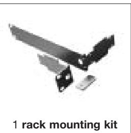
You can use the HUB 4000 as a standalone unit or install it in a 19" rack using the supplied rack mounting kit.
Refer to figs. 3.1 and 3.2. See SR 4000 manual for details.
2.2 Unpacking
Check that the packaging contains all of the components listed above. Should anything be missing, please contact your AKG dealer.
2.3 Optional Accessories
MCS 4000 control software
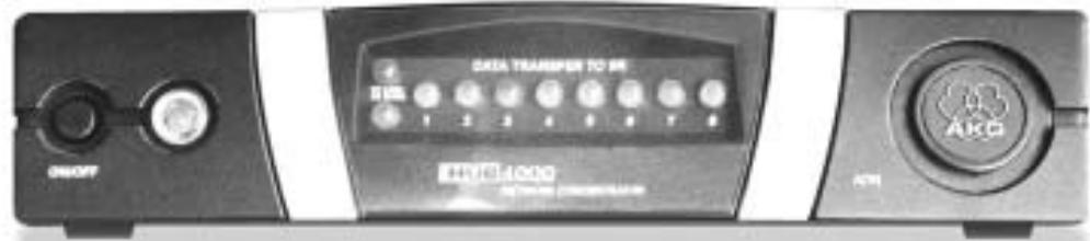
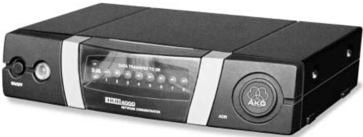
ON/OFF: Switches power to the unit on and off. The status LED next to the ON/OFF key will be lit green to indicate power is on.
PC LINK: This green LED will be lit constantly to indicate the unit is connected to an Ethernet network.
PC DATA: This green LED will flash to indicate the unit is receiving or sending data.
DATA TRANSFER TO SR 1-8: These blue LEDs indicate the status of data exchange between the HUB 4000 and the SR 4000 receivers connected to it. Each LED is assigned to one of the rear panel SR 1 through SR 8 data ports.
Each LED indicates the following conditions:
LED flashing: Data is being exchanged between the assigned data port on the HUB 4000 and the connected SR 4000 receiver.
LED flashing slowly (approx. once every 3 seconds): There is a communication problem between the assigned data port on the HUB 4000 and the connected SR 4000 receiver (hard or software error, defective data cable, etc.).
LED is dark: No receiver is connected to the assigned data port or the connection has been interrupted.
ADR: Located beneath the cover with the AKG logo is a bank of four DIP switches for setting the IP address of the HUB 4000.
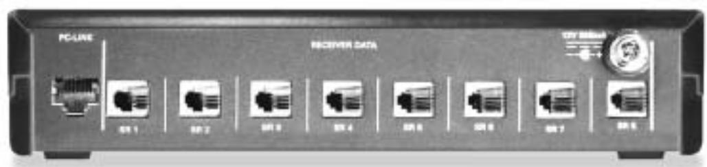
PC LINK: This RJ 45 socket accepts the connecting cable to the computer.
The connecting cable is not supplied with the unit. To connect the unit directly to a computer, use a crossover Ethernet cable. To connect the unit to a standard Ethernet hub, use a straight-through Ethernet cable.
RECEIVER DATA SR 1 - SR 8: RJ 11 sockets for connecting up to eight SR 4000 receivers.
12 V/500 mA: Locking DC input for connecting the included power supply (12 VDC, 500 mA).

Operate the equipment with the included power supply with an output voltage of 12 VDC, 500mA only. Using adapters with an AC output and/or a different output voltage may cause serious damage to the unit.
2.4 Controls
2.4.1 Front Panel
Fig. 1: Front panel controls.
Refer to fig. 1.
2.4.2 Rear Panel
Fig. 2: HUB 4000 rear panel.
Refer to fig. 2.
Note:
Warning!
3 Setting Up

Prior to setting up the unit, check that the AC mains voltage stated on the included power supply is identical to the AC mains voltage available where you will use your system. Using the power supply with a different AC voltage may cause damage to the unit.
- Use a crossover Ethernet cable to connect the HUB 4000 to a computer.
- Connect the PC LINK socket on the HUB 4000 to a network input on the computer or Ethernet card. (For details refer to the manual of your computer.)
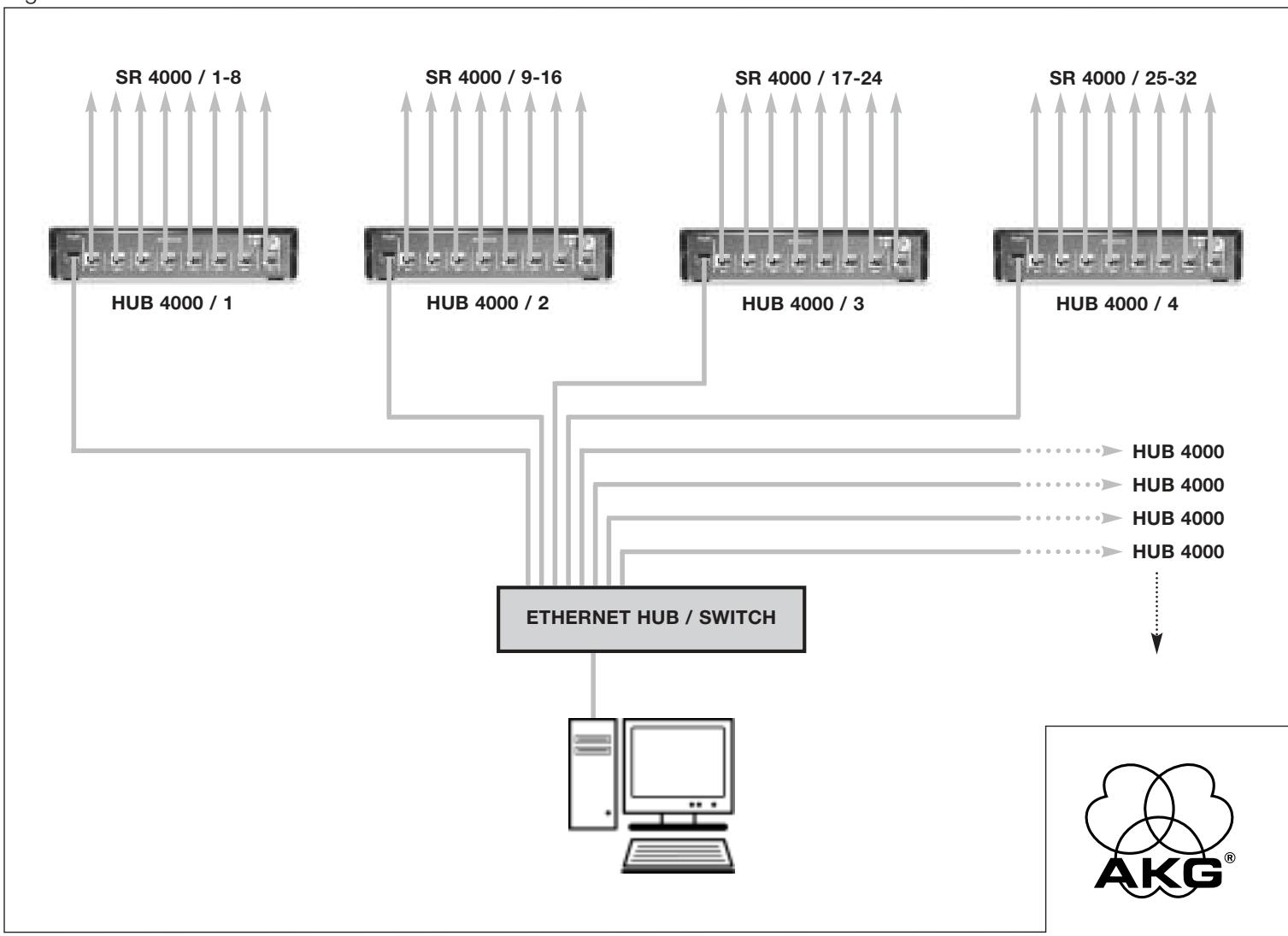
A single HUB 4000 allows you to control up to eight SR 4000 receivers from a computer. You can use one or more commercial Ethernet hubs to daisy-chain several HUB 4000s and control the entire setup from the computer. The number of receivers you can actually control on your computer will ultimately depend on the size and resolution of your monitor.
- Connect the Ethernet hub to the computer referring to the manual(s) of the Ethernet hub and/or computer.
- Plug a straight-through Ethernet cable into the PC LINK socket of each HUB 4000.
Important!
3.1 Data Connections
3.1.1 Direct Connection to the Computer
Refer to fig. 4.
3.1.2 Connecting to the
Computer via an Ethernet Hub
Refer to fig. 5.
- Plug the other end of each network cable to an unused output on (one of) your Ethernet hub(s).
3.1.3 Connecting Receivers
Refer to fig. 4 or 5.
- Be sure not to use any cables other than the supplied data cables with RJ 11 connectors.
- Connect the DATA socket on each SR 4000 receiver to one of the RECEIVER DATA sockets SR 1 to SR 8 on the HUB 4000 rear panel.
3.2 Assigning IP Addresses
Refer to fig. 6.
Each unit within the network needs its own, unambiguous IP address.
- The IP address of each HUB 4000 is factory-set to 192.168.0.4. The related combination of the ADR DIP switches is "1111".
Important!

Before connecting the unit to power, check that the IP address (ADR combination) of the unit is not identical to any other IP address previously assigned within the network. IP addresses assigned to multiple units may cause data transmission problems.
Important!

If you daisy-chain several HUB 4000s, remember to assign to the hubs consecutive IP addresses in ascending order to make sure the computer will correctly identify and control all HUB 4000s.
Refer to Table 1.
- You may assign any IP address between 192.168.0.4 and 192.168.0.19 to the HUB 4000 directly connected to the computer (hub no. 1). Assign the next higher IP address to the next HUB 4000 in your chain referring to Table 1. Enter the selected IP address of the first HUB 4000 in the MCS 4000 control program to enable the program to control the hubs correctly.
Table 1: IP addresses for 16 hubs.
| Hub no. | ADR switch positions | IP address | |
| 0..down | 1...up | ||
| 1 | 1111 | 192.168.0.4 | |
| 2 | 1110 | 192.168.0.5 | |
| 3 | 1101 | 192.168.0.6 | |
| 4 | 1100 | 192.168.0.7 | |
| 5 | 1011 | 192.168.0.8 | |
| 6 | 1010 | 192.168.0.9 | |
| 7 | 1001 | 192.168.0.10 | |
| 8 | 1000 | 192.168.0.11 | |
| 9 | 0111 | 192.168.0.12 | |
| 10 | 0110 | 192.168.0.13 | |
| 11 | 0101 | 192.168.0.14 | |
| 12 | 0100 | 192.168.0.15 | |
| 13 | 0011 | 192.168.0.16 | |
| 14 | 0010 | 192.168.0.17 | |
| 15 | 0001 | 192.168.0.18 | |
| 16 | 0000 | 192.168.0.19 | |
3.2.1 Setting IP addresses
Refer to Table 1.
- Remove the cover of the ADR switch bank.
- Check that the current IP address has not been assigned to any other unit within the network yet.
- If the current IP address has been assigned to another unit within the network, set a new IP address that has not been assigned to any other unit.
Important!

Upon having set a new IP address, switch power to the unit off and back on. The new IP address will not become active before you have switched power back on.
- Replace the ADR switch bank cover.
3.3 Connecting to Power
Refer to fig. 4.
- Check that the AC mains voltage stated on the included power supply is identical to the AC mains voltage available where you will use your system. Using the power supply with a different AC voltage may cause damage to the unit.
- Plug the DC cable on the included power supply into the 12 V/500 mA socket on the HUB 4000 rear panel and screw down the DC connector.
- Plug the power cable on the power supply into a convenient power outlet.
3.4 Powering Up/Down
- To switch power to the unit on, press the ON/OFF key.
The status LED next to the ON/OFF key will be lit, the blue DATA TRANSFER LEDs will illuminate starting from the center and extinguish to indicate the unit is initialized and ready to operate. - To switch power to the unit off, press the ON/OFF key again.
3.5 Setting Up the Computer
Make sure to assign an unambiguous IP address to the network card on the computer to which you connected the HUB 4000(s). Select a network card address that differs from any HUB 4000 IP address in the network but is within the same network segment, preferably 192.168.0.1. The subnet mask of the hub network segment is always 255.255.255.0.
3.6 Testing the Hubs
To test the hubs, use the ping
3.7 Operating the Network
To control the entire network (hubs and connected receivers) from your computer, you will need the optional MCS 4000 software. Refer to the MCS 4000 manual.
- Disconnect the power supply from the power outlet.
- Use a cloth moistened (not wet!) with water to clean the surfaces of the equipment.

Never use caustic or scouring cleaners or cleaning agents containing alcohol or solvents since these may damage the enamel or plastic parts.
Important!
Important!

5 Troubleshooting
| Problem | Possible Cause | Remedy |
| All LEDs remain dark on powering up. | • Power supply is not connected to HUB 4000 and/or power outlet. | • Connect power supply to HUB 4000 and/or power outlet. |
| PC LINK LED remains dark on powering up. | • HUB 4000 is not connected to computer/Ethernet card/Ethernet hub. | • Connect HUB 4000 to computer/Ethernet card/Ethernet hub. |
| DATA TRANSFER TO SR LED(s) remain(s) dark | • No receiver connected. | • Connect receiver(s). |
| DATA TRANSFER TO SR LED(s) is (are) lit constantly. | 1. Data cable(s) disconnected during data transfer. 2. Data cable(s) defective. | 1. Switch HUB 4000 OFF, connect data cable, switch HUB 4000 back ON. 2. Switch HUB 4000 OFF, replace data cable, switch HUB 4000 back ON. Should the problem persist, contact your nearest AKG Service Center. |
| DATA TRANSFER TO SR LEDs flash from center outward approx. every 2 seconds. | • Internal error. | • Switch unit OFF, wait for 10 seconds, switch unit back ON. Should the problem persist, contact your nearest AKG Service Center. |
| POWER, PC LINK, and PC DATA LEDs are lit constantly after power-up. | • Internal error. | • Switch unit OFF, wait for 10 seconds, switch unit back ON. Should the problem persist, contact your nearest AKG Service Center. |
6 Specifications

Power supply 12 VDC ±2 V
Current consumption 65 mA ±20 mA
Ambient temperature -10°C to +60°C
Connectors for SR 4000 receivers RJ11
Ethernet connector RJ45
Size 200× 190× 44mm (7.8 x 7.5 x 1.7 in.)
Weight approx. 970g (2.2 lbs.)
This equipment fulfills the following European standards:
EN 300422-2 V1.1.1
EN 301489-9 V1.3.1
EN 60065:2002
1.1 Sécurité
Conector Ethernet RJ45
Dimensiones 200 x 190 x 44 mm
Peso AFPX.970g
5 Resolver problemas
Conector Ethernet RJ45
Dimensoes 200 x 190 x 44 mm
Peso aprox. 970 g
H A Harman International Company
AKG Acoustics GmbH
BodenseestraBe 228, D-81243 München/GERMANY; Tel: (+49 89) 87 16-0, Fax: (+49 89) 87 16-200, www.kg.acoustics.de, e-mail: info@akg-acoustics.de Hotline: (+49 89) 87 16-22 50, hotline@akq.com
AKG ACOUSTICS, U.S.
914 Airpark Center Drive, Nashville, TN 37217, U.S.A., Tel: (+1 615) 620-3800, Fax: (+1 615) 620-3875, www.akgusa.com, e-mail: akgusa@harman.com
For other products and distributors worldwide see our website: www.akg.com
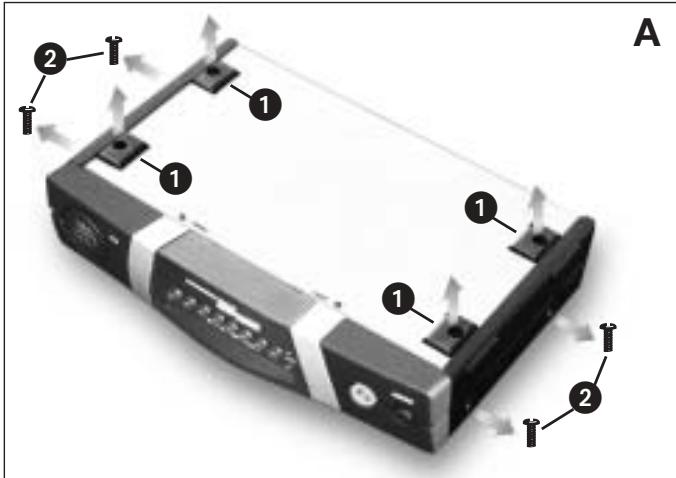
Fig. 3.1
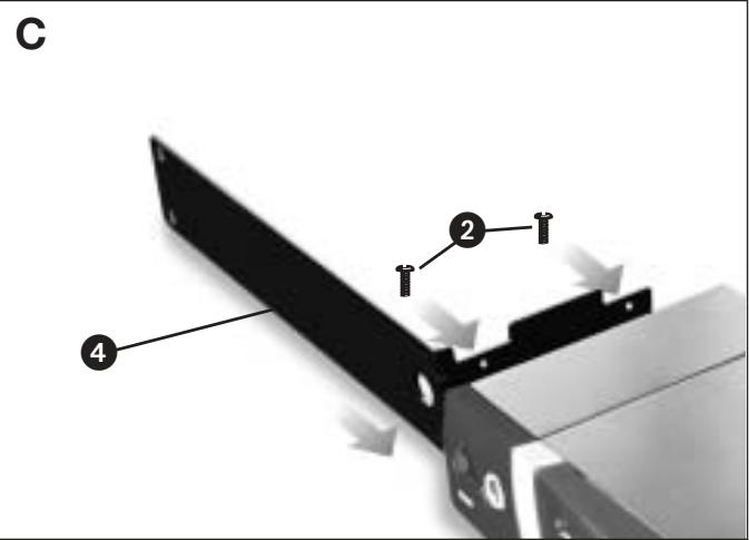
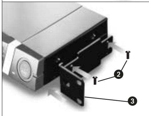
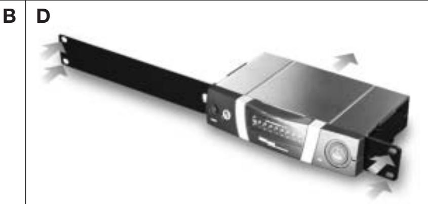
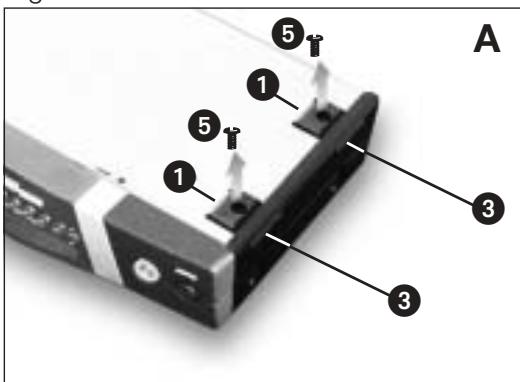
Fig. 3.2

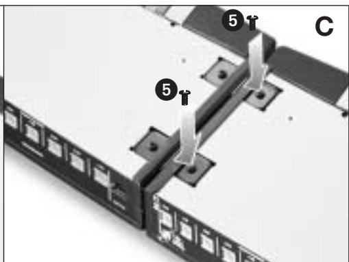
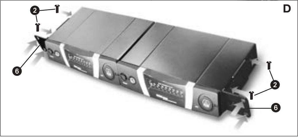
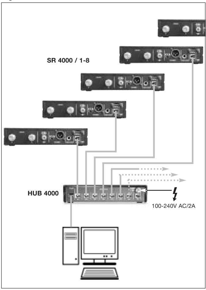
Fig. 4
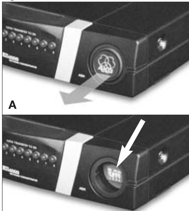
Fig. 6
B
HUB 4000
Fig. 5
DECLARATION OF CONFORMITY
Document No.367 / 06 - 2003 replaces No.
Type of Product: Network Concentrator
Brand, Model No.: HUB 4000 (including power supply)
Drawing-No.: 2999 Z 00..
Manufacturer: AKG Acoustics GmbH A-1230 Wien, Lemböckgasse 21 - 25 AUSTRIA
We declare that the above mentioned product is in conformity with the following European Directive:
No. 99/5 EC; Radio Equipment and
Telecommunications Terminal Equipment
The conformity is achieved by fulfilling the following European Standard(s):
EN 301489-9 V1.3.1; EN 60065:2002
Product testing was carried out by:
MIKES BABT Product Service GmbH
Ohmstrasse 2-4
94342 Strasskirchen, Germany
Manufacturer's Signature:
luiaod
Managing Director
Dr. Hugo Lenhard-Backhaus
This declaration certifies the accordance with the above mentioned EC-Directive but does not assure certain attributes of the product.