
PS 4000 W - Wireless Microphone AKG - Free user manual and instructions
Find the device manual for free PS 4000 W AKG in PDF.
| Product Type | Antenna splitter for UHF wireless microphone systems |
| Brand | AKG |
| Model | PS 4000 W |
| Carrier frequency range | 500 - 865 MHz |
| RF inputs | 2 BNC connectors, 50 ohms (ANTENNA A IN, ANTENNA B IN) |
| RF outputs | 10 BNC connectors, 50 ohms (8 to receivers + 2 LINK for cascading) |
| Attenuation (CLA) | 0, 2, 4, 6, 8, 10, 12, 14 dB, switchable via DIP switches |
| Power supply | 12 V DC via included power adapter or via central power supply PSU 4000 (optional) |
| Dimensions (W x D x H) | 200 x 190 x 44 mm |
| Weight | Approximately 970 g |
| Rack mounting | Half-width 19" for 1 U, can be placed side by side with two splitters |
| Number of supported channels | Up to 4 receivers per splitter, cascading possible for installations up to 50 channels |
| LED indicators | Blue OK LEDs for antenna supply voltage, ERROR LED for fault |
| Maintenance and cleaning | Clean with a soft, slightly damp cloth, disconnect before cleaning |
| Safety instructions | Do not expose to moisture, do not open, use the supplied power adapter, observe antenna installation distances |
| Spare parts and repairability | Repair only by AKG authorized personnel. Optional accessories: SRA 2 B/W antennas, RA 4000 B/W antennas, AB 4000 amplifiers, ASU 4000 power supply |
| General information | Compliant with European standards, declaration of conformity available at www.akg.com |
Frequently Asked Questions - PS 4000 W AKG
User questions about PS 4000 W AKG
0 question about this device. Answer the ones you know or ask your own.
Ask a new question about this device
Download the instructions for your Wireless Microphone in PDF format for free! Find your manual PS 4000 W - AKG and take your electronic device back in hand. On this page are published all the documents necessary for the use of your device. PS 4000 W by AKG.
USER MANUAL PS 4000 W AKG
Please read the manual before using the equipment!
MODE D'EMPLOI p. 20
1 Safety and Environment 12
1.1 Safety 12
1.2 Environment. 12
2 Description 12
2.1 Introduction 12
2.2 Packing List. 12
2.3 Optional Accessories 12
2.4 Description 13
2.4.1 Front Panel 13
2.4.2 Rear Panel 13
2.5 PSU 4000 Central Power Supply (optional) 14
2.6 Receiving Antennas (optional) 14
2.6.1 SRA 2 B/W 14
2.6.2 RA 4000 B/W 14
3 Getting Started 14
3.1 Rack Mounting a Single Antenna Splitter 14
3.2 Rack Mounting Two Antenna Splitter's Side by Side 14
3.3 Setting Up Antennas 14
3.3.1 Placement 14
3.3.2 Mounting Antennas on Floor Stands 15
3.3.3 Wall/Ceiling Mounting 15
3.4 Connecting Antennas 15
3.4.1 Single-channel System with Passive Antennas 15
3.4.2 Single-channel System with Active Antennas 15
3.5 Multichannel Systems with PS 4000 W Antenna Splits 16
3.6 The CLA Switch Bank 16
4 Operating Notes 18
4.1 General Hints 18
4.2 Systems with Distributed Power Supplies 18
4.2.1 Powering Up 18
4.2.2 Powering Down. 18
4.3 Systems with PS 4000 W Optional Central Power Supplies. 18
4.3.1 Powering Up 18
4.3.2 Powering Down. 18
5 Cleaning 18
6 Troubleshooting 18
7 Specifications 19
Figs. 8 through 13 56
FCC Statement
This equipment has been tested and found to comply with the limits for a Class B digital device, pursuant to Part 15 of the FCC Rules. These limits are designed to provide reasonable protection against harmful interference in a residential installation. This equipment generates, uses, and can radiate radio frequency energy and, if not installed and used in accordance with the instructions, may cause harmful interference to radio communications. However, there is no guarantee that interference will not occur in a particular installation. If this equipment does cause harmful interference to radio or television reception, which can be determined by turning the equipment off and on, the user is encouraged to try to correct the interference by one or more of the following measures:
Reorient or relocate the receiving antenna.
- Increase the separation between the equipment and the receiver.
- Connect the equipment into an outlet on a circuit different from that to which the receiver is connected.
- Consult the dealer or an experienced radio/TV technician for help.
Shielded cables and I/O cords must be used for this equipment to comply with the relevant FCC regulations.
Changes or modifications not expressly approved in writing by AKG Acoustics may void the user's authority to operate this equipment.
This device complies with Part 15 of the FCC Rules. Operation is subject to the following two conditions: (1) this device may not cause harmful interference, and (2) this device must accept any interference received, including interference that may cause undesired operation.
1.1 Safety
1 Safety and Environment
- Do not spill any liquids on the equipment and do not drop any objects through the ventilation slots in the equipment.
- The equipment may be used in dry rooms only.
- The equipment may be opened, serviced, and repaired by authorized personnel only. the equipment contains no user-serviceable parts.
- Before connecting the equipment to power, check that the AC mains voltage stated on the supplied power supply is identical to the AC mains voltage available where you will use the equipment.
- Operate the equipment with the supplied 12 VDC power supply. Using adapters with an AC output and/or a different output voltage may cause serious damage to the equipment.
- If any solid object or liquid penetrates into the equipment, shut down the sound system immediately. Disconnect the power supply from the power outlet immediately and have the equipment checked by AKG service personnel.
- If you will not use the equipment for a long period of time, disconnect the power supply from the power outlet. Please note that the equipment will not be fully isolated from power when you set the power switch to OFF.
- Do not place the equipment near heat sources such as radiators, heating ducts, or amplifiers, etc. and do not expose it to direct sunlight, excessive dust, moisture, rain, mechanical vibrations, or shock.
- To avoid hum or interference, route all audio lines, particularly those connected to the microphone inputs, away from power lines of any type. If you use cable ducts, be sure to use separate ducts for the audio lines.
- Clean the equipment with a moistened (not wet) cloth only. Be sure to disconnect the power supply from the power outlet before cleaning the equipment! Never use caustic or scouring cleaners or cleaning agents containing alcohol or solvents since these may damage the enamel and plastic parts.
- Use the equipment for the applications described in this manual only. AKG cannot accept any liability for damages resulting from improper handling or misuse.
1.2 Environment


2 Description
- The power supply will draw a small amount of current even when the equipment is switched off. To save energy, disconnect the power supply from the power outlet if you will leave the equipment unused for a long period of time.
- When scrapping the equipment, separate the case, circuit boards, and cables, and dispose of all components in accordance with local waste disposal rules.
- The packaging of the equipment is recyclable. Dispos of the packaging in an appropriate container provided by the local waste collection/recycling entity and observe all local legislation relating to waste disposal and recycling.
2.1 Introduction
Thank you for purchasing an AKG product. This Manual contains important instructions for setting up and operating your equipment. Please take a few minutes to read the instructions below carefully before operating the equipment. Please keep the Manual for future reference. Have fun and impress your audience!
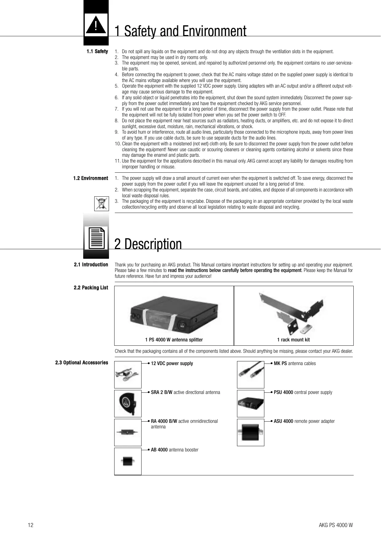
2.2 Packing List
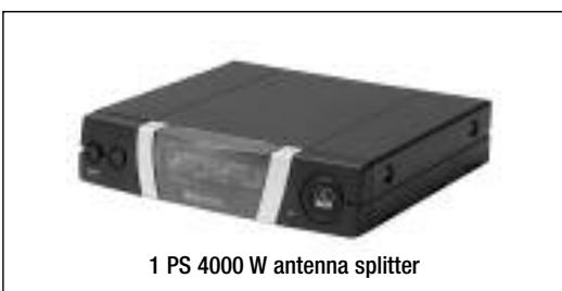
Check that the packaging contains all of the components listed above. Should anything be missing, please contact your AKG dealer.
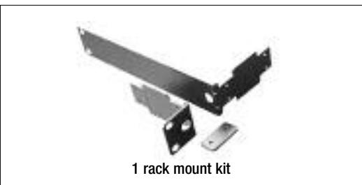
2.3 Optional Accessories
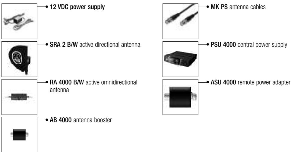
The PS 4000 W is an antenna splitter for setting up UHF multichannel systems with up to four receivers per antenna splitter. (Note that the number of channels you can actually operate simultaneously depends on local frequency plans.)
The PS 4000 W features two rear panel antenna inputs for connecting SRA 2 B/W or RA 4000 B/W active antennas with built-in boosters. Each antenna input provides a 12 VDC supply voltage for powering up to three active antenna components, e.g., one active antenna and two AB 4000 antenna boosters. Also located on the rear panel are two sets of four antenna output connectors for up to four diversity receivers and two additional antenna outputs for feeding the antenna signal to several additional PS 4000 W antenna splitters.
The PS 4000 W is housed in a 1 U, half-rack case so you can mount two antenna splitters in a single rack space.
The PS 4000 W can be powered from an optional local power supply. For systems with more than four channels, we recommend using an optional PSU 4000 central power supply for three antenna splitters each.
Both the antenna boosters and the antenna splitter are wideband devices for the entire UHF band.
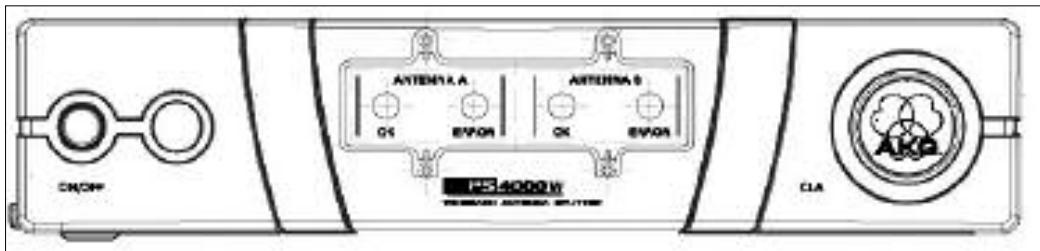
The antenna splitter front panel provides the following controls and indicators:
ON/OFF: Press this key to switch power to the unit ON. Press again to switch power to the unit OFF.
ANTENNA A, ANTENNA B: The blue OK LED will be lit for as long as the ANTENNA A IN/ANTENNA B IN input provides the correct supply voltage for active components.
Should the supply voltage at an input be shorted or fail (drop below 2 V) the OK LED for that input will extinguish and the red ERROR LED be lit instead.
- The two OK LEDs do NOT indicate the operating status of the connected antenna booster and therefore will not go out when you disconnect an antenna cable.
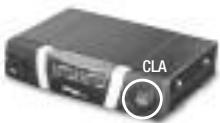
CLA: The round plate with the AKG logo covers a bank of three DIP switches for matching the antenna inputs (ANTENNA A IN, ANTENNA B IN) to the length of the connected cable run.
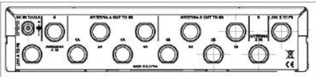
Fig. 2: PS 4000 W rear panel.
The PS 4000 W rear panel provides the following inputs and outputs:
DC IN 12 V/2A: Input jack for an optional 12 VDC power supply or optional PSU 4000 central power supply.
ANTENNA A IN, ANTENNA B IN: BNC input connectors for SRA 2 B/W, or RA 4000 B/W remote antennas. When using diversity receivers you will need two receiving antennas (optional). Each antenna input provides a 12 VDC supply voltage for an active antenna.
ANTENNA A OUT TO SR: The four BNC connectors 1A through 4A deliver the antenna signals for the A inputs of up to four diversity receivers. All unused outputs are electrically terminated automatically.
ANTENNA B OUT TO SR: The four BNC connectors 1B through 4B deliver the antenna signals for the B inputs of up to four diversity receivers. All unused outputs are electrically terminated automatically.
In addition to the antenna signals, outputs 1A through 4A and 1B through 4B provide a 12 VDC supply voltage for the connected receivers.
- The only way to ensure that outputs 1A through 4B/Will provide sufficient current to power the connected receivers is to connect the antenna splitter to an optional PSU 4000 central power supply.
- If you power the PS 4000 W antenna splitter from an optional local power supply, make sure to power each receiver from a local (optional) power supply, too. If you connect receivers to the antenna splitter without connecting each receiver to a power supply and AC power, the antenna splitter's standard power supply may be damaged due to overload.
LINK A TO PS, LINK B TO PS: These two BNC outputs carry the RF signal of the two antennas A and B. You can connect the LINK outputs to the antenna inputs of another PS 4000 W antenna splitter to daisy-chain several antenna splitters. Note that you will need one optional PSU 4000 central power supply each to power three PS 4000 W antenna splitters.
2.4.1 Front Panel
Fig. 1: PS 4000 W front panel.
Note:
Refer to Table 1 on page 17.
2.4.2 Rear Panel
Important!
See also Wiring Diagrams figs. 10 through 13.
2.5 PSU 4000 Central Power Supply (optional)
The PSU 4000 central power supply delivers a 12 VDC, 2 A secondary voltage for powering three PS 4000 W antenna splitters and the receivers (12 max.) connected to the antenna splitters. For details refer to the PSU 4000 user manual.
2.6 Receiving Antennas (optional)
Passive and active directional antennas as well as passive and active omnidirectional antennas are available for the PS 4000 W antenna system. All antennas are wideband devices for the entire UHF band. The active antennas are powered by the PS 4000 W antenna splitter via the antenna cables. For complex systems with long antenna cables, we recommend powering each active antenna from a PSU 4000 central power supply via an ASU 4000 remote power adapter.
2.6.1 SRA 2 B/W
The SRA 2 B/W is an active directional antenna with a rugged, water-resistant case designed specifically for indoor and outdoor use at a distance from the performance area. An integrated high-performance antenna booster allows you to position the antenna up to 100m (330 ft.) away from the receiver. Using RG213 antenna cables and two AB 4000 antenna boosters in series, you can set up the SRA 2 B/W even 200m (660 ft.) away from the receiver. The antenna provides a BNC output, status LED, and integrated stand adapter.
2.6.2 RA 4000 B/W
The RA 4000 B/W is an active omnidirectional antenna with a rugged, water-resistant case designed specifically for indoor and outdoor use in close proximity to the performance area. An integrated high-performance antenna booster allows you to position the antenna up to 100m (330 ft.) away from the receiver. Using RG213 antenna cables and two AB 4000 antenna boosters in series, you can set up the RA 4000 B/W even 200m (660 ft.) away from the receiver. The antenna provides a BNC output, status LED, and integrated stand adapter.
3 Getting Started
3.1 Rack Mounting
a Single Antenna Splitter
Refer to fig. 8.
- Unscrew the four rubber feet (1) from the antenna splitter bottom panel.
- Unscrew the two fixing screws (2) from each side panel.
- Use the fixing screws (2) to screw the short bracket (3) to one side panel and the long bracket (4) to the other side panel. The brackets are contained in the supplied rack mounting kit.
- Install the antenna splitter in your rack.
3.2 Rack Mounting Two Antenna Splitters Side by Side.
Refer to fig. 9.
- Unscrew the four rubber feet (1) from each antenna splitter's bottom panel and remove the screws (5) from the rubber feet (1).
- Unscrew the two fixing screws (2) from the right-hand side panel of one antenna splitter and from the left-hand side panel of the other antenna splitter.
- Remove the plastic covers (3) from the side panels with the fixing screws (2) still on.
- Insert one connecting strip (4) into each free slot in the side panel of the first antenna splitter, making sure to align the hole in each connecting strip (4) with the appropriate threaded hole in the antenna splitter bottom panel.
- Fix the two connecting strips (4) on the first antenna splitter using two of the screws (5) you removed from the rubber feet.
- To join the two antenna splitters, slide the connecting strips (4) on the first antenna splitter through the free slots in the side panel of the second antenna splitter. Make sure to align the hole in each connecting strip (4) with the appropriate threaded hole in the bottom panel of the second antenna splitter.
- Fix the two connecting strips (4) on the second antenna splitter using two of the screws (5) you removed from the rubber feet.
- Screw a short bracket (6) to the outer side panel of each antenna splitter using for each bracket two of the screws (2) you removed from the antenna splitter side panels.
- Install the antenna splitters in your rack.
Note:
- Be sure to keep the remaining screws (5) for later use.
3.3 Setting Up Antennas
The following hints on placing antennas apply to both single-channel and multichannel systems with any number of channels.
3.3.1 Placement
Reflections off metal parts, walls, ceilings, etc. or the shadow effects of musicians and other people may weaken or cancel the direct transmitter signal. For best results, place the antennas as follows:
- Place the antennas near the performance area (stage). Make sure, though, that the transmitter will never get any closer to the antennas than 16 ft. (5 m). Place the two antennas at least 8 inches. (20 cm) from each other.
- There should always be a direct line of sight between the transmitter and antennas.
- Place the receiver at least 5 ft. (1.5 m) away from any big metal objects, walls, scaffolding, ceilings, etc.
- Do not place antennas in wall recesses.
- Place antennas at least 5 ft. (1.5 m) away from any equipment that may emit RF radiation such as lighting racks, fluorescent lamps, digital effects units, or PCs.
- If you set up two antennas side by side (e.g., for diversity reception), check that the two antennas are spaced at least 20cm (8 in.) apart.
3 Getting Started
3.3.2 Mounting Antennas on Floor Stands
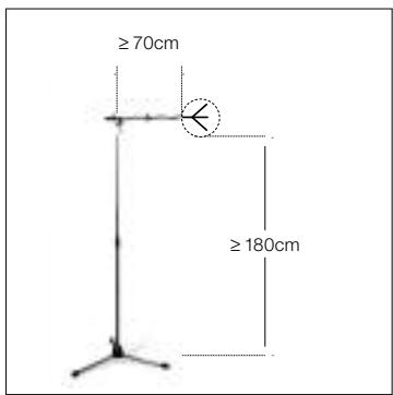
When mounting the antennas on floor stands, be sure to proceed as follows:
- Use the supplied SA 63 or the integrated stand adapter to mount the antenna on the boom of a boom stand.
- Pull the boom out all the way to one side to make sure the antenna will be at least 28 inches (70 cm) away from the stand.
- Extend the stand high enough to place the boom at least 6 ft. (1.8 m) above the floor.
- Wind the antenna cable around the boom. Do not allow the cable to sag below the boom because this may degrade the reception quality.
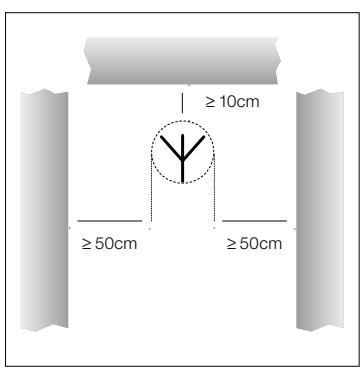
Fig. 3: Antenna mounted on floor stand
If you mount your antennas on a wall or ceiling, be sure to keep the following minimum distances:
- Mount the antenna at least 10cm (4 in.) in front of and at a minimum lateral distance of 50~cm (20 in.) from any walls or other plane surfaces, metal grids, or metal scaffolding.
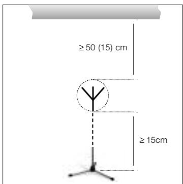
Fig. 4: Minimum distances from plane surfaces.
- Make sure the antenna will sit at least 15cm (6 in.) above the floor or 50~cm (20 in.) from the ceiling (or 15cm (6 in.) if you route the cable to the antenna from above).
For a single-channel system, you need no antenna splitter. Connect the antennas to the receiver directly.
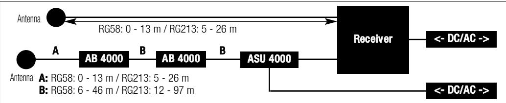
Fig. 5: Minimum distances from floor and ceiling.
- Measure the cable run between the receiver and each antenna.
- Refer to Table 1 on page 17 to find out whether you will need to break the cable run down into several cables and insert one or two AB 4000 antenna boosters. Table 1 states the maximum acceptable cable lengths for RG58 and RG213 cables separately.
- Connect an antenna cable to each antenna.
- Referring to Table 1, connect the antennas to the antenna inputs on the receiver. If you need one or two AB 4000 antenna boosters, you will need to insert an ASU 4000 remote power adapter between the receiver and the first antenna booster.
- Check that the AC mains voltage stated on the power supplies for the ASU 4000 and the receiver is identical to the AC mains voltage available where you will use your system. Using the power supplies with a different AC voltage may cause damage to the unit.
-
Connect the remote power adapter and the receiver to their respective power supplies and connect each power supply to a convenient power outlet.
-
Measure the cable run between the receiver and each active antenna.
- Refer to Table 1 on page 17 to find out whether you will need to break the cable run down into several cables and insert one or two AR 4000 antenna boosters. Table 1 states the maximum acceptable cable lengths for RG58 and RG213 cables separately.
- Connect an antenna cable to each antenna.
- Referring to Table 1, connect each antenna to one or two AB 4000 antenna boosters (if necessary), an ASU 4000 remote power adapter, and to the appropriate antenna input on the receiver.
3.3.3 Wall/Ceiling Mounting
3.4 Connecting Antennas
3.4.1 Single-channel System with Passive Antennas
Refer to Table 1 on page 17 and fig. 6.
Refer to fig. 6.

Fig. 6: Wiring a single-channel system with passive antennas and different antenna cable runs.
Important!
3.4.2 Single-channel System with Active Antennas
Refer to Table 1 on page 17 and fig. 7 on page 16.
3 Getting Started
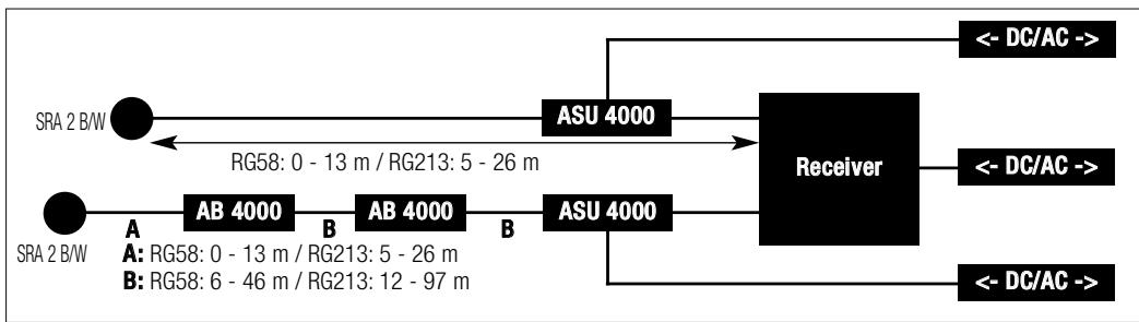
Fig. 7: Wiring a single-channel system with active antennas and different antenna cable runs.

3.5 Multichannel Systems with PS 4000 W Antenna Splitters
- Check that the AC mains voltage stated on the power supplies for the two ASU 4000s and the receiver is identical to the AC mains voltage available where you will use your system. Using the power supplies with a different AC voltage may cause damage to the unit.
- Connect the remote power adapters and the receiver to their respective power supplies and connect each power supply to a convenient power outlet.
For wiring examples for multichannel systems, refer to figs. 10 through 13 on page 56.
When setting up a multichannel system, remember the following points:
- You can connect up to four receivers to each PS 4000 W antenna splitter.

- If you power both the antenna splitter and the receivers from (optional) local power supplies, make absolutely sure to connect the receiver power supplies to AC power before connecting the antenna splitter power supply to AC power. Connecting the antenna splitter to power first may cause damage to the antenna splitter power supply due to the load presented by the receivers.
-
For large systems with up to 50 channels you can daisy-chain the required number of antenna splitters:
-
Connect the LINK outputs on the first antenna splitter to the ANTENNA IN connectors on the next antenna splitter and so on.
-
We recommend powering large systems from optional PSU 4000 central power supplies for three antenna splitters and four receivers each.
-
Each antenna input on the antenna splitter is capable of powering a maximum of three active components (e.g., RA 4000 B/W + 2 x AB 4000) via the antenna cables. In the following cases you will need an ASU 4000 remote power adapter to power active components (each ASU 4000 is capable of powering up to three active components, too):
-
The cable run from the antenna splitter to an active component is long enough to reduce the supply voltage below the acceptable minimum.
- A device (e.g., an antenna combiner*) in the line between the PS 4000 W and an active component interrupts the DC supply voltage across the antenna cable.
Note:
- The ZAPD 21 antenna combiner from Mini Circuit feeds the supply voltage through. Similar devices from other manufacturers may not do so.
- You have used an antenna combiner to connect two antenna lines to the same antenna input. If you use three or more active components in one antenna line, insert an ASU 4000 remote power adapter between the antenna combiner and the first of the active components. If the number of active components in both lines totals more than three, be sure to insert an ASU 4000 remote power adapter into each line. The remote power adapter prevents the antenna splitter power supply from being overloaded.
3.6 The CLA Switch Bank
The RF signal level at each antenna input on the antenna splitter(s) depends on the frequency band, antenna type, cable type, and cable length.
To ensure optimum signal level at the antenna input, set the CLA switches on each antenna booster and on the antenna splitter(s) as shown in Table 1 below.
Refer to Table 1 on page 17.
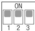
- Remove the cover of the CLA switch bank.
- Set the three DIP switches as required for your frequency band, antenna model, cable type, and cable length.
- Replace the cover.
3 Getting Started


A

A

A

B

B
CLA
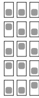
14 dB
12 dB
10 dB
8 dB
6 dB
4 dB
2 dB
0 dB
.
| BANDS I + II | A | |||||
| SRA 2 B/W | RA 4000 B/W | |||||
| RG58 (m) | RG213 (m) | CLA (dB) | RG58 (m) | RG213 (m) | CLA (dB) | |
| 53 - 57 | 111 - 121 | 0 | 38 - 43 | 79 - 89 | 0 | |
| 48 - 53 | 100 - 111 | 2 | 33 - 38 | 68 - 79 | 2 | |
| 43 - 48 | 89 - 100 | 4 | 28 - 33 | 58 - 68 | 4 | |
| 38 - 43 | 79 - 89 | 6 | 23 - 28 | 47 - 58 | 6 | |
| 33 - 38 | 68 - 79 | 8 | 18 - 23 | 37 - 47 | 8 | |
| 28 - 33 | 58 - 68 | 10 | 13 - 18 | 26 - 37 | 10 | |
| 23 - 28 | 47 - 58 | 12 | 8 - 13 | 16 - 26 | 12 | |
| 18 - 23 | 37 - 47 | 14 | 3 - 8 | 5 - 16 | 14 | |
| B | ||
| RG58(m) | RG213(m) | CLA(dB) |
| 41 - 46 | 87 - 97 | 0 |
| 36 - 41 | 76 - 87 | 2 |
| 31 - 36 | 66 - 76 | 4 |
| 26 - 31 | 55 - 66 | 6 |
| 21 - 26 | 45 - 55 | 8 |
| 16 - 21 | 34 - 45 | 10 |
| 11 - 16 | 24 - 34 | 12 |
| 6 - 11 | 13 - 24 | 14 |
| BANDS III + IV | A | |||||
| SRA 2 B/W | RA 4000 B/W | |||||
| RG58 (m) | RG213 (m) | CLA (dB) | RG58 (m) | RG213 (m) | CLA (dB) | |
| 50 - 55 | 105 - 115 | 0 | 36 - 40 | 75 - 85 | 0 | |
| 45 - 50 | 95 - 105 | 2 | 31 - 36 | 65 - 75 | 2 | |
| 40 - 45 | 85 - 95 | 4 | 26 - 31 | 55 - 65 | 4 | |
| 36 - 40 | 75 - 85 | 6 | 21 - 26 | 45 - 55 | 6 | |
| 31 - 36 | 65 - 75 | 8 | 17 - 21 | 35 - 45 | 8 | |
| 26 - 31 | 55 - 65 | 10 | 12 - 17 | 25 - 35 | 10 | |
| 21 - 26 | 45 - 55 | 12 | 7 - 12 | 15 - 25 | 12 | |
| 17 - 21 | 35 - 45 | 14 | 2 - 7 | 5 - 15 | 14 | |
| B | ||
| RG58(m) | RG213(m) | CLA(dB) |
| 39 - 44 | 83 - 93 | 0 |
| 35 - 39 | 73 - 83 | 2 |
| 30 - 35 | 63 - 73 | 4 |
| 25 - 30 | 53 - 63 | 6 |
| 20 - 25 | 43 - 53 | 8 |
| 15 - 20 | 33 - 43 | 10 |
| 11 - 15 | 23 - 33 | 12 |
| 6 - 11 | 13 - 23 | 14 |
| BANDSV + VI | A | |||||
| SRA 2 B/W | RA 4000 B/W | |||||
| RG58 (m) | RG213 (m) | CLA (dB) | RG58 (m) | RG213 (m) | CLA (dB) | |
| 47 - 51 | 100 - 110 | 0 | 33 - 38 | 71 - 81 | 0 | |
| 42 - 47 | 90 - 100 | 2 | 29 - 33 | 62 - 71 | 2 | |
| 38 - 42 | 81 - 90 | 4 | 24 - 29 | 52 - 62 | 4 | |
| 34 - 38 | 71 - 81 | 6 | 20 - 24 | 43 - 52 | 6 | |
| 29 - 34 | 62 - 71 | 8 | 16 - 20 | 33 - 43 | 8 | |
| 24 - 29 | 52 - 62 | 10 | 11 - 16 | 24 - 33 | 10 | |
| 20 - 24 | 43 - 52 | 12 | 7 - 11 | 14 - 24 | 12 | |
| 16 - 20 | 33 - 43 | 14 | 2 - 7 | 5 - 14 | 14 | |
| B | ||
| RG58(m) | RG213(m) | CLA(dB) |
| 37 - 41 | 79 - 88 | 0 |
| 32 - 37 | 69 - 79 | 2 |
| 28 - 32 | 60 - 69 | 4 |
| 23 - 28 | 50 - 60 | 6 |
| 19 - 23 | 40 - 50 | 8 |
| 14 - 19 | 31 - 40 | 10 |
| 10 - 14 | 21 - 31 | 12 |
| 6 - 10 | 12 - 21 | 14 |
| BAND VII | A | |||||
| SRA 2 B/W | RA 4000 B/W | |||||
| RG58 (m) | RG213 (m) | CLA (dB) | RG58 (m) | RG213 (m) | CLA (dB) | |
| 56 - 60 | 132 - 140 | 0 | 44 - 46 | 102 - 108 | 0 | |
| 51 - 56 | 120 - 132 | 2 | 40 - 44 | 93 - 102 | 2 | |
| 46 - 51 | 108 - 120 | 4 | 36 - 40 | 84 - 93 | 4 | |
| 41 - 46 | 97 - 108 | 6 | 32 - 36 | 75 - 84 | 6 | |
| 36 - 41 | 83 - 97 | 8 | 28 - 32 | 66 - 75 | 8 | |
| 31 - 36 | 71 - 83 | 10 | 25 - 28 | 57 - 66 | 10 | |
| 26 - 31 | 60 - 71 | 12 | 21 - 25 | 48 - 57 | 12 | |
| 23 - 26 | 52 - 60 | 14 | 18 - 21 | 42 - 48 | 14 | |
| B | ||
| RG58(m) | RG213(m) | CLA(dB) |
| 49 - 50 | 110 - 118 | 0 |
| 47 - 49 | 100 - 110 | 2 |
| 42 - 47 | 90 - 100 | 4 |
| 36 - 42 | 81 - 90 | 6 |
| 31 - 36 | 70 - 81 | 8 |
| 27 - 31 | 60 - 70 | 10 |
| 23 - 27 | 50 - 60 | 12 |
| 19 - 23 | 44 - 50 | 14 |
| BAND VIII | A | |||||
| SRA 2 B/W | RA 4000 B/W | |||||
| RG58 (m) | RG213 (m) | CLA (dB) | RG58 (m) | RG213 (m) | CLA (dB) | |
| 53 - 56 | 122 - 131 | 0 | 40 - 44 | 94 - 101 | 0 | |
| 48 - 53 | 110 - 122 | 2 | 35 - 40 | 82 - 94 | 2 | |
| 43 - 48 | 99 - 110 | 4 | 30 - 35 | 70 - 82 | 4 | |
| 38 - 43 | 88 - 99 | 6 | 25 - 30 | 58 - 70 | 6 | |
| 33 - 38 | 79 - 88 | 8 | 22 - 25 | 46 - 58 | 8 | |
| 28 - 33 | 63 - 74 | 10 | 16 - 22 | 34 - 46 | 10 | |
| 23 - 28 | 50 - 63 | 12 | 11 - 16 | 22 - 34 | 12 | |
| 20 - 23 | 43 - 50 | 14 | 7 - 11 | 15 - 22 | 14 | |
Table 1: CLA DIP switch positions depending on frequency band, antenna, cable type, and cable length.
| B | ||
| RG58(m) | RG213(m) | CLA(dB) |
| 43 - 46 | 102 - 107 | 0 |
| 38 - 43 | 88 - 102 | 2 |
| 33 - 38 | 76 - 88 | 4 |
| 28 - 33 | 64 - 76 | 6 |
| 23 - 28 | 52 - 64 | 8 |
| 18 - 23 | 40 - 52 | 10 |
| 13 - 18 | 28 - 40 | 12 |
| 10 - 13 | 20 - 28 | 14 |
4 Operating Notes
4.1 General Hints
-
Be sure to assign a separate carrier frequency to each wireless channel (transmitter and receiver).
-
Do not operate two or more wireless channels on the same frequency at the same time and location. This would cause unwanted noise due to radio interference.
Important!
- To prevent damage from overloading the antenna splitter power supply, always switch power to the various components of your system on and off in the order described in sections 4.2 and 4.3.
4.2 Systems with Distributed Power Supplies 4.2.1 Powering Up
- Switch power to all transmitters ON.
- Switch ON all receivers connected to the antenna splitter.
- Press the ON/OFF key on the antenna splitter to switch power to the antenna splitter ON. The blue OK LEDs and the green status LEDs on the connected active components will illuminate.
4.2.2 Powering Down
- Switch OFF all receivers connected to the antenna splitter.
- Switch power to all transmitters OFF.
- Press the ON/OFF key on the antenna splitter to switch power to the antenna splitter OFF. The blue OK LEDs and the green status LEDs on the connected active components will extinguish.
4.3 Systems with PSU 4000 Central Power Supplies 4.3.1 Powering Up
- Switch the PSU 4000 central power supply ON.
- Switch power to all transmitters ON.
- Press the ON/OFF key on the antenna splitter to switch power to the antenna splitter ON. The blue OK LEDs and the green status LEDs on the connected active components will illuminate.
- Switch ON all receivers connected to the antenna splitter.
4.3.2 Powering Down
- Switch OFF all receivers connected to the antenna splitter.
- Switch power to all transmitters OFF.
- Press the ON/OFF key on the antenna splitter to switch power to the antenna splitter OFF. The blue OK LEDs and the green status LEDs on the connected active components will extinguish.
- Switch the PSU 4000 central power supply OFF.

5 Cleaning
- Use a soft cloth moistened with water to clean the antenna splitter surfaces.

6 Troubleshooting
| Problem | Possible Cause | Remedy |
| No sound. | 1. Power supplies/PSU 4000 not connected to power outlet(s). 2. DC cables not connected or defective. 3. Antennas not connected. 4. Power supplies/PSU 4000 defective. | 1. Connect power supplies/PSU 4000 to power outlet(s). 2. Connect or replace DC cables. 3. Connect antennas. 4. Contact your nearest AKG Service Center. |
| No or poor reception on some channels. | 1. Transmitter and/or receiver switched OFF. 2. Transmitter batteries down. 3. Power supply of receiver or feeder cable from PSU 4000 to receiver a) makes poor contact or b) is defective. 4. Transmitter and receiver of dead channel are tuned to different frequencies. 5. Transmitter or receiver defective. | 1. Switch transmitter and/or receiver ON. 2. Replace transmitter batteries. 3. a) Check power supply or feeder cable connectors for secure fit or b) Replace power supply or feeder cable. 4. Tune transmitter and receiver to the same frequency. Refer to the transmitter and receiver Instruction Manuals. 5. Contact your nearest AKG Service Center. |
| Green LED on an active antenna component is dark. | 1. Antenna cable not connected or makes poor contact. 2. Antenna cable defective. 3. Active antenna component defective. | 1. Connect antenna cable or check connectors for secure fit. 2. Replace antenna cable. 3. Contact your nearest AKG Service Center. |
| One of the ERROR LEDs on the antenna splitter is lit. | 1. Supply voltage for active antenna components shorted out. 2. Supply voltage for active antenna components too low because cable run is too long. | 1. Check all cables and active antenna components con- nected to antenna splitter. 2. Refer to Table 1 to check cable lengths and use short- er cables or break down cable run and insert ASU 4000(s) (see also Wiring Diagrams). |
PS 4000 W Antenna Splitter
| Type: | 2 x 1 to 4 receivers + 2 x 1 PS (for daisy-chaining) |
| Carrier range: | 500 to 865 MHz |
| Attenuation: | 0, 2, 4, 6, 8, 10, 12, 14 dB switchable |
| RF inputs: | 2 x BNC sockets, 50 ohms |
| RF outputs: | 10 x BNC sockets, 50 ohms |
| Power requirement: | 12 VDC |
| Size: | 200 x 190 x 44 mm (7.8 x 7.5 x 1.7 in.) |
| Weight: | approx. 970 g (2.2 lbs.) |
| AB 4000 Antenna Amplifier | |
| Carrier range: | 500 to 865 MHz |
| Gain: | approx. 17 dB to 3.5 dB, selectable |
| RF input: | 1 x BNC, 50 ohms |
| RF output: | 1 x BNC, 50 ohms |
| Power requirement: | 8 VDC, supplied through connecting cable from PS 4000 W or ASU 4000 |
| Size: | 110 x 35 mm (4.3 x 1.4 in.) |
| Weight: | approx. 150 g (5.3 oz.) |
| RA 4000 B/W Omnidirectional Booster Antenna | |
| Carrier range: | 500 to 865 MHz |
| Antenna gain + booster gain: | 17 dB |
| RF input: | 1 x BNC socket, 50 ohms |
| RF output: | 1 x BNC socket, 50 ohms |
| Power requirement: | 8 VDC, supplied through connecting cable from PS 4000 W or ASU 4000 |
| Size: | 235 x 38.5 mm / 9.3 x 1.5 in. |
| Weight: | 65 g (2.29 oz.) |
| SRA 2 B/W Active Directional Antenna | |
| Carrier range: | 500 to 865 MHz |
| Antenna gain + booster gain: | 21.5 dB |
| Coverage angle: | 70° |
| Size: | 230 x 240 x 26 mm (9 x 9.5 x 1 in.) |
| Weight: | approx. 250 g (8.8 oz.) |
| ASU 4000 Remote Power Adapter | |
| Carrier range: | 500 to 865 MHz |
| RF input: | 1 x BNC socket, 50 ohms |
| RF output: | 1 x BNC socket, 50 ohms |
| Power requirement: | 12 VDC |
| Size: | 78 x 50 x 50 mm / 3.1 x 2 x 2 in. |
| Weight: | approx. 150 g (5.3 oz.) |
| This product conforms to the standards listed in the Declaration of Conformity. To order a free copy of the Declaration of Conformity, visit http://www.akg.com or contact sales@akg.com. | |
Antenne directive passive SRA 2 B/W
3.4Ligar as antennas 51
3.4.1 Sistema monocanal com antenas passivas 51
3.4.2 Sistema monocanal com antennas ativas 51
3.5 Sistemas multicanais com splitter de antennas PS 4000 W 51
3.6 Comutador CLA 52
3.4 Ligar as antennas
3.4.1 Sistema monocanal com antenas passivas
6 Resolver problemas
Complex system (RF connections)
For other products and distributors worldwide visit www.akg.com

H A Harman International Company
Technische Änderungen vorbehalten. Specifications subject to change without notice. Ces caractéristiques sont susceptibles de modifi-cations. Ci riserviamo il diritto di effettuare modifiche tecniche. Nos reservamos el Derecho de introducir modificaciones Tecnicas. Especificações sujeitas a mudanças sem aviso precedo.
Printed in Austria.
02/07/9100 U 1239

- FCC Statement
- Safety
- Safety and Environment
- Environment
- Description
- Introduction
- Packing List
- Optional Accessories
- Front Panel
- Note:
- Rear Panel
- Important!
- PSU 4000 Central Power Supply (optional)
- Receiving Antennas (optional)
- SRA 2 B/W
- RA 4000 B/W
- Getting Started
- Rack Mounting
- a Single Antenna Splitter
- Rack Mounting Two Antenna Splitters Side by Side.
- Setting Up Antennas
- Placement
- Connecting Antennas
- Single-channel System with Passive Antennas
- Single-channel System with Active Antennas
- Multichannel Systems with PS 4000 W Antenna Splitters
- The CLA Switch Bank
- Operating Notes
- General Hints
- Systems with Distributed Power Supplies 4.2.1 Powering Up
- Powering Down
- Systems with PSU 4000 Central Power Supplies 4.3.1 Powering Up
- Powering Down
- Cleaning
- Troubleshooting
- Ligar as antennas
- Sistema monocanal com antenas passivas
- Resolver problemas
- H A Harman International Company
Brand : AKG
Model : PS 4000 W
Category : Wireless Microphone