
HT 4000 - Wireless Microphone System AKG - Free user manual and instructions
Find the device manual for free HT 4000 AKG in PDF.

| Product Type | Handheld Transmitter for Wireless Microphone System |
| Brand | AKG |
| Model | HT 4000 |
| Carrier Frequency Ranges | 650-680, 680-710, 720-750, 760-790, 790-820, 835-863 MHz |
| Number of Carriers | Up to 1200 |
| Modulation | FM |
| Nominal Deviation | ±20 kHz |
| Audio Bandwidth | 35 - 20,000 Hz |
| Harmonic Distortion at 1 kHz | <0.3% at nominal deviation |
| Signal-to-Noise Ratio | Typ. 118 dB(A) |
| RF Power | 30 mW ERP |
| Max Input Level (SPL) | 140 dB SPL at nominal deviation |
| Power Consumption | <125 mA |
| Power Supply | 2 AA 1.5 V batteries or BP 4000 rechargeable battery |
| Battery Life | 15 h with alkaline batteries, 12 h with BP 4000 |
| Dimensions | 239 x 39 mm |
| Net Weight | 320 g (without batteries) |
| Operating Modes | LOCK, SETUP, SILENT |
| Main Functions | MUTE switch, backlit LCD display, frequency and gain adjustment, preset selection, color coding, interchangeable microphone heads |
| Interchangeable Microphone Heads | D 880 WL1, C 900 WL1, D 3700 WL1, D 3800 WL1, C 5900 WL1, C 535 WL1 |
| Cleaning | Soft cloth slightly moistened with water |
| Safety | Do not expose to sunlight, dust, humidity, rain, vibrations; dispose of batteries according to regulations |
| Recommended Accessories | CU 4000 Charger, CH 4000 Case, W 880, W 3001, W 23 Windscreens, BP 4000 Battery |
Frequently Asked Questions - HT 4000 AKG
User questions about HT 4000 AKG
0 question about this device. Answer the ones you know or ask your own.
Ask a new question about this device
Download the instructions for your Wireless Microphone System in PDF format for free! Find your manual HT 4000 - AKG and take your electronic device back in hand. On this page are published all the documents necessary for the use of your device. HT 4000 by AKG.
USER MANUAL HT 4000 AKG
wireless microphone syste
HT 4000
handheld transmitter
C∈①
H A Harman International Company
AKG Acoustics GmbH
Bodenseestrae 228, D-81243 Munchen/GERMANY, Tel: (+49 89) 87 16-0, Fax: (+49 89) 87 16-200, www.akq-acoustics.de, e-mail: info@akq-acoustics.de
AKG ACQUSTICS, U.S.
914 Airpark Center Drive, Nashville, TN 37217, U.S.A., Tel: (+1 615) 620-3800, Fax: (+1 615) 620-3875, www.akgusa.com, e-mail: akgusa@harman.com
For other products and distributors worldwide see our website: www.akq.com

Inhaltsverzeichnis
Seite
3.11Forschatten in Oil ENIT Model
3.4.1Einschatten inSilENT-Moder
3.0.2 Frequency-Measure
3.7 Menrkanala
41.3SETUP-andSILENTModem
4.1.2 SETOF-ANDGILENT-MODS
1.3 Battery wire and
4.6 MIKROIONTECHNIK.
1 Safety and Environment 15
1.1 Safety 15
1.2 Environment 15
2 Description 15
2.1 Introduction. 15
2.2 Unpacking. 15
2.3 Optional Accessories. 15
2.4 Description 15
2.4.1 Controls 16
2.4.2 Interchangeable Microphone Elements 16
3 Setting Up 17
3.1 Mounting the Microphone Element 17
3.2 Inserting Batteries 17
3.3 Operating Modes 17
3.4 Powering Up 17
3.4.1 Powering Up in SILENT Mode 17
3.4.2 Powering Up in LOCK Mode 18
3.5 Switching OFF. 18
3.5.1 LOCK Mode 18
3.5.2 SETUP and SILENT Modes. 18
3.6 Checking/Setting the Carrier Frequency 18
3.6.1 Preset Menu 18
3.6.2 Frequency Menu 20
3.7 Multichannel Systems 21
3.8 Setting Input Gain 21
3.8.1 Setting Gain Manually 21
3.8.2 Using Automatic Gain Mode 22
4 Operating Notes 22
4.1 Status Screens and Setup Menus 22
4.1.1 LOCK Mode 22
4.1.2 SETUP and SILENT Modes. 23
4.2 Selecting Modes 23
4.3 Muting the Microphone 23
4.4 Changing the Color Code 23
4.5 Replacing Batteries 23
4.6 Microphone Technique 23
4.6.1 Working Distance and Proximity Effect 23
4.6.2 Angle of Incidence 24
4.6.3 Feedback 24
4.6.4 Backing Vocals 24
4.7 Multichannel Systems 24
4.8 Battery Care 24
5 Cleaning. 24
6 Error Messages 24
7 Specifications 25
FCC Statement
This equipment has been tested and found to comply with the limits for a Class B digital device, pursuant to Parts 74, 15, and 90 of the FCC Rules. These limits are designed to provide reasonable protection against harmful interference in a residential installation. This equipment generates, uses, and can radiate radio frequency energy and, if not installed and used in accordance with the instructions, may cause harmful interference to radio communications. However, there is no guarantee that interference will not occur in a particular installation. If this equipment does cause harmful interference to radio or television reception, which can be determined by turning the equipment off and on, the user is encouraged to try to correct the interference by one or more of the following measures:
- Reorient or relocate the receiving antenna.
- Increase the separation between the equipment and the receiver.
- Connect the equipment into an outlet on a circuit different from that to which the receiver is connected.
- Consult the dealer or an experienced radio/TV technician for help.
Shielded cables and I/O cords must be used for this equipment to comply with the relevant FCC regulations.
Changes or modifications not expressly approved in writing by AKG Acoustics may void the user's authority to operate this equipment.
This device complies with Part 15 of the FCC Rules. Operation is subject to the following two conditions:
(1) this device may not cause harmful interference, and (2) this device must accept any interference received, including interference that may cause undesired operation.
- Do not expose the equipment to direct sunlight, excessive dust, moisture, rain, mechanical vibrations, or shock.
- Be sure to dispose of used batteries as required by local waste disposal rules. Never throw batteries into a fire (risk of explosion) or garbage bin.
- When scrapping the equipment, remove the batteries, separate the case, circuit boards, and cables, and dispose of all components in accordance with local waste disposal rules.
1.1 Safety
1.2 Environment
2 Description

Dear Customer:
Thank you for purchasing an AKG product. This Manual contains important instructions for setting up and operating your equipment. Please take a few minutes to read the instructions below carefully before operating the equipment. Please keep the Manual for future reference. Have fun and impress your audience!
2.1 Introduction
1 HT 4000 handheld transmitter

2 x 1.5 V AA size batteries
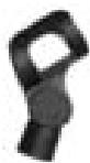
1 SA 63 stand adapter

1 Color Coding Kit
2.2 Unpacking
Check that the package contains all the parts listed above. If anything is missing, please contact your AKG dealer.
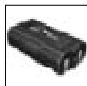
BP 4000:3 V rechargeable battery pack

W 880: Foam windscreen for D 880 WL1
- CU 4000: Charger for two transmitters or BP 4000 battery packs
W 3001: Foam windscreen for D 3700 WL1, D 3800 WL1, C 5900 WL1
- CH 4000: Carrying case for one complete WMS 4000 system
W 23: Foam windscreen for C 535 WL1
2.3 Optional Accessories
The HT 4000 handheld transmitter and matching microphone elements (optional) provide the same acoustic performance as the equivalent hardwire microphone versions. The microphone elements available for the HT 4000 have been specifically designed for vocal use.
The HT 4000 operates in one subband up to 30MHz wide within the 650MHz to 862MHz UHF carrier frequency band. Within the subband, you can either set the carrier frequency directly in 25-kHz increments or select one of the Subchannels of the Preset Frequency Groups of your transmitter.
The transmitter provides three operating modes:
In LOCK mode, the microphone output signal is transmitted to the receiver. All setup functions and controls except for the MUTE switch are electronically locked to prevent parameters from being readjusted unintentionally during a performance or lecture. The LCD screen displays the "LOCK" label.
SETUP mode allows you to adjust and save the carrier frequency and input gain.
In SILENT mode, power to the transmitter is on, but no RF signal is transmitted. We recommend using only this mode for setting the carrier frequency. This is the only way to make sure you won't "go on air" on a frequency that is not allocated or coordinated and risk "jamming" some other radio service or active radio mic.
The backlit LCD screen indicates all important parameters, the current battery capacity, and the remaining time before the battery will be dead.
The transmitter uses a dipole antenna integrated in the body and can be powered from two standard AA size dry batteries or the optional BP 4000 battery pack from AKG.
Never use standard rechargeable batteries! These may damage the transmitter if the charging contacts are shorted and will provide no remaining battery life indication. AKG will accept no liability for any damage resulting from the use of standard rechargeable batteries.
2.4 Description
Important!
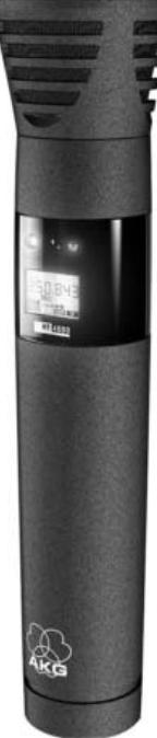
2.4.1 Controls Refer to fig. 1.
1 Status LED: This bicolor LED indicates the current operating status of the transmitter: Green: The output signal of the microphone element is fed to the transmitter, which transmits the audio signal to the receiver.
Red: The Status LED is lit red if
-
the audio signal is muted while the RF section remains active. This prevents unwanted noise from becoming audible in the signal chain;
-
approximately 60 minutes before the batteries or BP 4000 battery pack will be dead; and
- while the transmitter recalls the carrier frequency from memory after you turned power to the transmitter on. Unless you muted the audio signal, the status LED will change to green as soon as the frequency has been recalled.
2 Display: The transmitter provides a five-line LCD display:
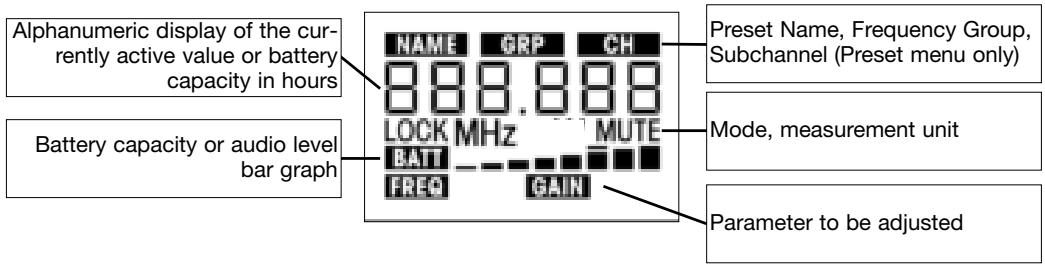
The display indicates all transmitter parameters:
-
Carrier frequency in MHz or as a Subchannel of a Frequency Group
-
Audio input level
-
Battery status and remaining operating time
-
Error messages
-
Setup menus: Frequency, Preset, Gain
The backlighting of the display comes on every time you actuate the jog switch and will switch off after approximately 10 seconds.
3 ON/OFF button: A long push (approx. 1.5 seconds) will switch power to the transmitter ON and activate the display (2) and status LED (1). The transmitter will be ready to operate after approx. 7 seconds.
A long push (approx. 1.5 seconds) in SETUP mode or SILENT mode will switch power to the transmitter OFF. In LOCK mode, the ON/OFF button is electronically locked to prevent power from being switched off unintentionally.
The ON/OFF button is recessed for added protection from unintentional actuation.
4 MUTE switch: Sliding the MUTE switch toward the outside of the transmitter (MUTE position) will mute the audio signal. The status LED (1) will change to red. Since power and the RF section remain ON, no unwanted noise will become audible from the sound system when you mute the audio signal. To switch the audio signal back on, slide the MUTE switch toward the inside of the transmitter (ON position). The status LED (1) will change to green.
The MUTE switch is active in all modes.
5 Charging contacts: The recessed charging contacts allow you to recharge the optional AKG BP 4000 battery pack on the optional CU 4000 charger without having to remove the battery pack from the transmitter.
6 Jog switch: Sets the various parameters of the transmitter. The jog switch has the following functions: Long push: toggles between LOCK and SETUP modes when the transmitter is ON. When power to the transmitter is OFF, a long push switches the transmitter ON and places it in SILENT mode. SETUP and SILENT modes only:
Short push: calls up a parameter for adjustment or confirms a selected value.
Turn left briefly to select a menu item or decrease a parameter value.
Turn right briefly to select a menu item or increase a parameter value.
Turn left or right and hold to scroll through available values.
7 Battery compartment cover: Screw-on tube covering the battery compartment.
8 Frequency sticker: Sticker attached to the transmitter shaft, indicating the available carrier frequency range and approval data.
9 Battery compartment accepting the two supplied 1.5 V AA size batteries or the optional BP 4000 battery pack.
10 Color code: If you use the transmitter within a multichannel system, you can remove the black paper strip and replace it with a different-color paper strip from the supplied Color Coding Kit to identify the various channels. You can even write or print additional information on the paper strips.
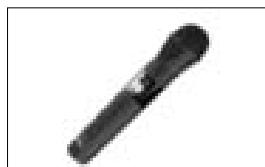
2.4.2 Interchangeable Microphone Elements (optional)
Refer to fig. 2.
The interchangeable microphone elements (11) D 880 WL1, C 900 WL1, D 3700 WL1, D 3800 WL1, C 5900 WL1, and C 535 WL1 are acoustically and mechanically identical to the equivalent hardwire versions. They feature the same transducer capsules and mechanical construction.
Extremely high gain before feedback, optimum handling noise rejection, ultimate protection from damage, and an integrated wind and pop screen are only the most impressive features of these microphones. For more details, refer to the respective AKG brochures.
Prior to setting up your WMS 4000, check that the transmitter and receiver are tuned to the same frequency, referring to section 3.6 and the receiver manual.
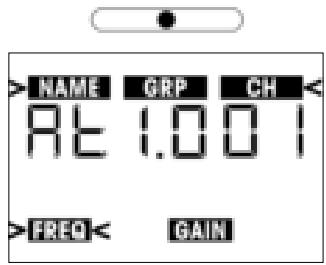
In the display illustrations in the following sections, flashing characters are identified by angle symbols "> and "< . All the values shown are examples of possible settings.
The " " symbol stands for a short push of the jog switch.
The " " symbol stands for a long push of the jog switch.
The " " symbol stands for turning the jog switch briefly to the left.
The " " symbol stands for turning the jog switch briefly to the right.
The " " symbol stands for turning the jog switch briefly to the left or right.
Screw the microphone element CW onto the thread on the transmitter. All electrical connections will be made automatically.
- Unscrew the battery compartment cover (1) CCW from the transmitter.
- Push the locking button (2) toward the microphone element to unlock the securing clamp (3).
Make sure to hold down the securing clamp (3) as you unlock it. The securing clamp is spring-loaded and may cause injury if it is allowed to jump out of the battery compartment. - Insert the two supplied batteries into the battery compartment, aligning the batteries with the polarity symbols inside the battery compartment.
If you insert the batteries the wrong way, the transmitter will not be powered.
- Press the securing clamp (3) down on the battery compartment to the point that the locking button (2) will engage and screw the battery compartment cover (1) back onto the transmitter CW.
Alternatively to the supplied dry batteries, you may use the optional BP 4000 battery pack from AKG. The BP 4000 fits into the battery compartment in the correct orientation only, so you cannot insert it the wrong way.
Never use standard rechargeable batteries! These may damage the transmitter if the charging contacts are shorted and will provide no remaining battery life indication. AKG will accept no liability for any damage resulting from the use of standard rechargeable batteries.
- LOCK mode: The transmitter transmits the microphone output signal to the receiver. All adjustment functions and controls except for the MUTE switch are electronically locked to prevent parameters from being readjusted unintentionally during a performance or lecture. The LCD screen displays the "LOCK" label.
- SETUP mode: The transmitter transmits the microphone output signal to the receiver. All controls are active. You can check all transmitter parameters and set the carrier frequency (refer to section 3.6) and input gain (refer to section 3.8).
- SILENT mode: Power to the transmitter is ON, but no RF signal is transmitted. The status LED remains dark. You can check all transmitter parameters and set the carrier frequency (refer to section 3.6) and input gain (refer to section 3.8).
We recommend setting the carrier frequency in SILENT mode only. This is the only way to make sure you won't "go on air" on a frequency that is not allocated or coordinated and risk "jamming" some other radio service or active radio mic.
Depending on the way you switch power to the transmitter ON, the transmitter will be in either LOCK mode or SILENT mode on powering up.
If you are not sure as to what carrier frequency the transmitter is tuned to, switch the transmitter to SILENT mode (refer to section 3.4.1 below) and check that the current carrier frequency is legal and identical to the frequency selected on the receiver.
- Push and hold the jog switch (6) until the backlighting of the display (2) comes on and the status LED (1) extinguishes. The display (2) will first show the firmware version and then the currently selected carrier frequency in MHz. As the backlighting goes out, the display changes as follows:
Important!
Note:
3.1 Mounting the Microphone Element
Refer to fig. 2.
3.2 Inserting Batteries Refer to fig. 3.
Warning!
Note:
Important!
3.3 Operating Modes
Important!
3.4 Powering Up
Important!
3.4.1 Powering Up in SILENT Mode
Refer to fig. 1.
The transmitter is now in SILENT mode.
- If the carrier frequency is not an allocated or coordinated one and/or different from the receiver frequency, set the transmitter to a suitable, legal frequency referring to section 3.6.
3.4.2 Powering Up in LOCK Mode Refer to fig. 1.
- Press the ON/OFF button (3) for approx. 1.5 seconds.
- As soon as the below screen appears on the display (2), the transmitter is in LOCK mode.
The "LOCK" label indicates that all controls except for the MUTE switch are electronically locked to prevent misadjustment.
Note:
If the microphone is muted, the "MUTE" label appears on the display and the status LED is lit red. If the microphone is active, "MUTE" will not appear and the status LED will be lit green.
3.5 Switching OFF Refer to fig.1. 3.5.1 LOCK Mode
- Push and hold the jog switch (6) until any one or more labels on the display (2) start flashing.
- Push and hold the ON/OFF button (3) until the message "oFF" appears on the display (2). The display goes dark and power to the transmitter is OFF.
3.5.2 SETUP and SILENT Modes
- Push and hold the ON/OFF button (3) until the message "oFF" appears on the display. The display goes dark and power to the transmitter is OFF.
3.6 Checking/Setting the Carrier Frequency Important!
If you are not sure as to what carrier frequency the transmitter is tuned to, place the transmitter into SILENT mode following steps 1 and 2 below. In SILENT mode, you can check and adjust the carrier frequency and input gain without transmitting a radio signal.
- If the transmitter is ON, switch it OFF.
- Push and hold the jog switch until the display backlighting comes on and the status LED extinguishes.
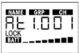
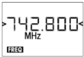
The display will first show the battery capacity in hours and as a bargraph and then the currently selected carrier frequency in MHz.
As the backlighting goes out, the display changes as follows:
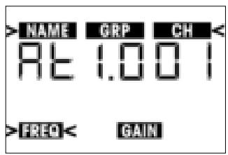
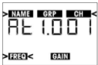
The transmitter is now in SILENT mode and the display shows the Preset menu.
- You can either select one of the Preset Subchannels from the Preset menu (section 3.6.1) or set the carrier frequency in 25-kHz increments in the Frequency menu (section 3.6.2). The spacing between Preset frequencies prevents any mutual interference.
3.6.1 Preset Menu
A Preset comprises one or two Groups of carrier frequencies. Group numbers are shown under the "GRP" label. Carrier frequencies are also called "Subchannels" whose numbers are indicated below the "CH" label. The spacing between these frequencies is wide enough to prevent any mutual interference (intermodulation). Presets make it much easier to design a multichannel system. They save time because you do not need to calculate your own carrier frequencies and help you avoid intermodulation problems. Each Preset has a one or two-character "NAME" relating to the country where the respective carrier frequencies are allocated (e.g., "AT" for Austria, "US" for the USA, or "UK" for Britain). The Preset names are sorted alphabetically.
When designing a multichannel system, make sure to use Subchannels within the same Group only. Using Subchannels of different Presets and/or Groups simultaneously may cause intermodulation.
Some Presets may be approved in more than one country. To check which Frequency Group(s) is (are) approved in your country, visit www.akgfrequency.at or contact your local regulation authority.
- Push the jog switch briefly. The "NAME" label and the name of the currently active Preset will start flashing.
If no Preset has been stored in memory, the 2nd line of the display shows "---".
- To select the next Preset, turn the jog switch briefly to the right.
To select the previous Preset, turn the jog switch briefly to the left.
- Having selected the desired Preset, push the jog switch briefly.
The "GRP" label and the number of the currently active Frequency Group will start flashing.
- To select the next higher Frequency Group number, turn the jog switch briefly to the right. The highest number available will be followed by "00".
To select the next lower Frequency Group number, turn the jog switch briefly to the left. "00" will be followed by the highest number available.
- Having selected the desired Frequency Group, push the jog switch briefly.
"CH" and the number of the currently active Subchannel start flashing. Each Subchannel represents one factory-preset, intermodulation-free carrier frequency.
- To select the next higher Subchannel number, turn the jog switch briefly to the right. The highest number available will be followed by "00".
To select the next lower Subchannel number, turn the jog switch briefly to the left. "00" will be followed by the highest number available.
- Having finished your settings, push the jog switch briefly. This brings up the following screen:

8a If you want to save the selected carrier frequency, push the jog switch briefly. The setting will be saved in memory and the display will change as follows:

8b If you'd rather not save the selected frequency, briefly turn the jog switch to the left or right.
This brings up the following screen:

Push the jog switch briefly. The transmitter will stay tuned to the original frequency and the display will revert to the following screen:
-
To switch the transmitter into LOCK mode:
-
Push and hold the ON/OFF button until the message "oFF" appears on the display. After approx. 1/2 second, the display will go dark as power to the transmitter is switched off.
- Switch the transmitter ON in LOCK mode, referring to section 3.4.2.
- To enter SETUP mode:
Push and hold the jog switch until the "LOCK" label disappears and one or more of the readouts in the current menu start flashing.
3.6.2 Frequency Menu
- To move from the Preset to the Frequency menu, turn the jog switch briefly to the left. The display will change like this:
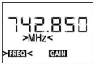
- To increase the frequency by 25kHz , turn the jog switch briefly to the right.
To decrease the frequency by 25kHz , turn the jog switch briefly to the left. - Having set the desired frequency, push the jog switch briefly. This brings up the following screen:

4a If you want to save the selected frequency, push the jog switch briefly. Your setting will be saved in memory and the display will change as follows:
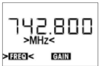
4b If you'd rather not save the selected frequency, briefly turn the jog switch to the left or right. This brings up the following screen:

- Push the jog switch briefly. The transmitter will stay tuned to the original frequency and the display will revert to the following screen:
-
You can now go on to set the input gain referring to section 3.8 or switch the transmitter to LOCK mode.
-
Be sure to assign a separate carrier frequency to each wireless channel (transmitter and receiver).
- To find intermodulation-free carrier frequencies quickly and easily, we recommend selecting all required carrier frequencies from the same Frequency Group within the same Preset.
If reception on the selected carrier frequency is poor, use Auto Channel Setup on the receiver to find the next clean Subchannel within the selected Frequency Group. Should you find no clean Subchannel, use Auto Group Setup on the receiver to select a different Frequency Group within the same Preset and selecet a new frequency for each transmitter and receiver.
Do not operate two or more wireless channels on the same frequency at the same time and location. This would cause unwanted noise due to radio interference.
3.7 Multichannel Systems
Note:
Important!
3.8 Setting Input Gain
You can set the transmitter input gain either in SILENT mode or in SETUP mode. We recommend setting the input gain in SETUP mode because you can switch to LOCK mode directly, without having to power down first.
- To move from LOCK mode to SETUP mode, push and hold the jog switch for approx. 1.5 seconds. The display will change as follows:

- Turn the jog switch briefly to the left once.
The display will show the current input gain in dB and the "GAIN" label will be flashing.

- Push the jog switch briefly.
The currently selected input gain value in dB will be flashing on the display:

-
You have now the choice of setting the input gain manually (section 3.8.1) or in automatic mode (section 3.8.2).
-
To increase the gain value by 1 dB, turn the jog switch briefly to the right.
To decrease the gain value by 1 dB, turn the jog switch briefly to the left. The readout "00" will be followed by "Auto" (refer to section 3.8.2).
- Push the jog switch briefly.
This brings up the following screen:

3.8.1 Setting Gain Manually
- If you want to save the new setting, push the jog switch briefly.
The display will show your new gain setting in dB and the "GAIN" label will be flashing. -
If you'd rather not save your setting, turn the jog switch briefly to the left or right. The display will change to "Save-n".
-
Push the jog switch briefly. The display will revert to the original setting, with the "GAIN" label flashing.
- To set input gain again, repeat steps 1 and 2 above.
- To return to LOCK mode, push and hold the jog switch for approx. 1.5 seconds.
3.8.2 Using Automatic Gain Mode
- From the Gain menu, hold the jog switch to the right until the display changes as follows:

- Push the jog switch briefly.
The message "tEST" will start flashing on the display.
- Talk or sing into the microphone as loud as you can.
The transmitter will automatically set the optimum input gain.
The display indicates the audio level by short lines. The peak level is indicated by a heavier line that will remain fixed for approx. 2 seconds.
- Push the jog switch briefly.
This brings up the following screen:

If you want to save the new setting, push the jog switch briefly.
The display will show your new gain setting in dB and the "GAIN" label will be flashing.
- If you'd rather not save your setting, turn the jog switch briefly to the left or right. The display will change to "Save-n".
- Push the jog switch briefly. The display will revert to the original setting, with the "GAIN" label flashing.
- To set input gain again, repeat steps 1 through 4 above.
- To return to LOCK mode, push and hold the jog switch for approx. 1.5 seconds.

4 Operating Notes
4.1 Status Screens and
Setup Menus
4.1.1 LOCK Mode
In LOCK mode, four status screens are available.
1. To scroll through the status screens in the order shown below, turn the jog switch briefly to the right.

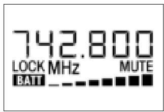
Frequency Screen: Carrier frequency in MHz, battery capacity bars. The "MUTE" label appears if the microphone is muted.

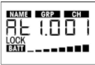
Preset Screen (comes up only if at least one Preset has been saved): Carrier frequency as Subchannel number within a Frequency Group, battery capacity bars. If the microphone is ON, the "MUTE" label is off.
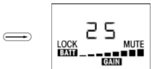
Gain Screen: Input gain in dB.

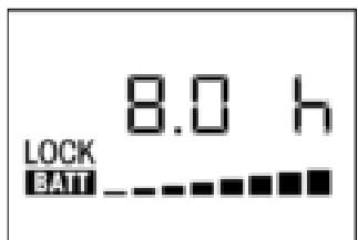
Battery Screen: Battery capacity in hours and as bar graph. If the microphone is ON, the "MUTE" label is off.
- To step through the above screens in reverse order, turn the jog switch briefly to the left.
In SETUP and SILENT modes, the various setup menus described in sections 3.4 through 3.8 come up in the order shown below:
- Preset Menu
- Frequency Menu
- Battery Screen
-
Gain Menu
-
To toggle between LOCK mode and SETUP mode, push and hold the jog switch for approx. 1.5 seconds. In LOCK mode, the "LOCK" label will be shown on the display.
The transmitter is fully functional in SETUP mode, too. Remember, though, that settings may change if you inadvertently actuate the jog switch. The transmitter will revert to LOCK mode after about 15 minutes.
- To toggle between LOCK or SETUP mode and SILENT mode:
- Switch power to the transmitter OFF.
-
Switch power to the transmitter ON by pushing and holding for approx. 1.5 seconds either the ON/OFF button to enter LOCK mode or the jog switch to enter SILENT mode.
-
To mute the microphone, slide the MUTE switch (4) toward the outside of the transmitter. The status LED (1) will change to red.
- To switch the microphone back ON, slide the MUTE switch (4) toward the inside of the transmitter. The status LED (1) will change to green.
The supplied Color Coding Kit includes pre-cut paper strips in various colors that you can assign to the various channels of a multichannel system. You can write or print additional information (e.g., channel number, frequency, performer's name, etc.) on each paper strip.
- Unscrew the battery compartment cover (1) CCW from the transmitter.
- Pull the color code holder (2) out of the transparent cover.
- Remove the desired paper strip (3) from the color code sheet and place the paper strip (3) on the color code holder (2).
- Slide the color code holder (2) below the transparent cover to the stop.
- Screw the battery compartment cover (1) back onto the transmitter CW.
In LOCK mode, the display constantly indicates the current battery capacity as a string of bars below the frequency readout.
If the "BATT" label starts flashing, a dash appears instead of the bars, and the status LED changes to red, replace the batteries or charge the BP 4000 battery pack as soon as possible.
You can check the remaining battery capacity at any time by turning the jog switch briefly to the left or right one to three times (depending on the currently active screen). The battery capacity will be displayed in hours and as a string of bars.
A handheld vocal microphone provides many ways of shaping the sound of your voice as it is heard over the sound system.
The following sections contain useful hints on how to use your HT 4000 handheld transmitter for best results.
Basically, your voice will sound the bigger and mellower, the closer you hold the microphone to your lips. Moving away from the microphone will produce a more reverberant, more distant sound as the microphone will pick more of the room's reverberation.
You can use this effect to make your voice sound aggressive, neutral, insinuating, etc. simply by changing your working distance.
4.1.2 SETUP and SILENT Modes
4.2 Selecting Modes
Note:
4.3 Muting the Microphone Refer to fig. 1.
4.4 Changing the Color Code Refer to fig. 4.
4.5 Replacing Batteries Refer to fig. 3.
4.6 Microphone Technique
4.6.1 Working Distance and Proximity Effect Refer to fig. 5.
| Proximity effect is a more or less dramatic boost of low frequencies that occurs when you sing into the microphone from less than 2 inches. It gives more "body" to your voice and an intimate, bass-heavy sound. | |
| 4.6.2 Angle of Incidence Refer to fig. 5. | Sing to one side of the microphone or above and across the microphone's top. This provides a well-balanced, natural sound. If you sing directly into the microphone, it will not only pick up excessive breath noise but also overemphasize "sss", "sh", "tch", "p", and "t" sounds. |
| 4.6.3 Feedback Refer to fig. 6. | Feedback is the result of part of the sound projected by a speaker being picked up by a microphone, fed to the amplifier, and projected again by the speaker. Above a specific volume or "system gain" setting called the feedback threshold, the signal starts being regenerated indefinitely, making the sound system howl and the sound engineer desperately dive for the master fader to reduce the volume and stop the howling. To increase usable gain before feedback, plasce the main ("FOH") speakers in front of the microphones (along the front edge of the stage). If you use monitor speakers, be sure never to point any microphone directly at the monitors. Feedback may also be triggered by resonances depending on the acoustics of the room or hall. With resonances at low frequencies, proximity effect may cause feedback. In this case, it is often enough to move away from the microphone a little to stop the feedback. |
| 4.6.4 Backing Vocals Refer to fig. 7. | 1. Never let more than two persons share a microphone. 2. Ask your backing vocalists never to sing more than 35 degrees off the microphone axis. The microphone is very insensitive to off-axis sounds. If the two vocalists were to sing into the microphone from a wider angle than 35 degrees, you may end up bringing up the fader of the microphone channel far enough to create a feedback problem. |
| 4.7 Multichannel Systems | If reception on the selected carrier frequency is poor, use Auto Channel Setup on the receiver to find the next clean Subchannel within the selected Frequency Group. Should you find no clean Subchannel, use Auto Group Setup on the receiver to select a different Frequency Group within the same Preset and selecet a new frequency for each transmitter and receiver. |
| 4.8 Battery Care | 1. If you know you won't be using the transmitter fo more than a week, remove the batteries or BP 4000 battery pack from the transmitter. 2. Make it a habit to charge the BP 4000 battery pack fully every time you used the transmitter for at least one or two hours. This is a good way to prevent the battery pack from dying in the middle of the next gig. 3. Always charge the BP 4000 battery pack fully if you stroe it outside the transmitter. This will maintain the battery pack's capacity at a higher level for a longer time. |

5 Cleaning
To clean the transmitter surfaces, use a soft cloth moistened with water.

6 Error Messages
The following error messages may appear on the display upon powering up or during operation:
| Display Error Message | Problem | Remedy |
| Err.>rF< | PLL error. (Receiver unable to lock on to select- ed frequency.) | 1. Press jog switch briefly and set different fre- quency. 2. If problem persists, contact your AKG Service Center. |
| Err.>SYS< | Frequency settings cannot be changed. | 1. Switch power to transmitter OFF and back ON after about 10 seconds. 2. If problem persists, contact your AKG Service Center. |
| Err.>USr< | Last setting cannot be loaded. | 1. Set frequency again. 2. If problem occurs frequently, contact your AKG Service Center. |
| Err.>FrE< | Frequencies cannot be set in Frequency screen. | 1. Continue with previous setting. 2. Press jog switch briefly and set frequency from Preset screen. 3. If problem occurs frequently, contact your AKG Service Center. |
| Err.>PrE< (comes up on powering up or when trying to select a Preset. Message also appears on receiver.) | All Presets defective; you cannot select any Preset. | 1. Use frequency screen to set frequency (section 3.6.2). 2. Contact your nearest AKG Service Center. |
| Err.>PrE< (comes up on powering up only. Message will not appear on the receiver!) | One or more Presets defective. | 1. You can select Presets, but note that defective Presets will not be available. 2. Contact your nearest AKG Service Center. |
| Err.>rPt< | No remaining battery life data available. | 1. Check batteries: replace standard recharge-able batteries immediately with dry batteries or AKG BP 4000 battery pack. 2. Remove and reinsert BP 4000 battery pack. 3. If error persists, charge battery pack. 4. If error occurs with different battery packs or types of dry batteries, contact your nearest AKG Service Center. |
| Err.>AF< | No signal at audio input. | 1. Check microphone element. 2. Mount microphone element. 3. Briefly push jog switch. 4. If error occurs frequently, contact your nearest AKG Service Center. |
| Err.>Acc< | BP 4000 battery pack not ready to operate. | 1. Remove and reinsert BP 4000 battery pack. 2. If error persists, charge battery pack. 3. If error occurs frequently, contact your nearest AKG Service Center. |
| Err.>JoG< | Internal jog switch error. | 1. (Jog switch functions in spite of error message:) Switch power to transmitter off, wait for 10 seconds, and switch power back on. 2. (Jog switch fails to respond:) Remove and reinsert batteries/BP 4000 battery pack, and switch power to transmitter on. 3. If error persists, contact your nearest AKG Service Center. |
To delete an error message, push the jog switch.
For more hints on troubleshooting, refer to the SR 4000 receiver manual.

7 Specifications
| Carrier frequency ranges: | 650 – 680, 680 – 710, 720 – 750, 760 – 790, 790 – 820, 835 - 863 MHz |
| Carrier frequencies: | up to 1,200 |
| Modulation: | FM |
| Rated deviation: | ±20 kHz nominal |
| Audio bandwidth: | 35 to 20,000 Hz |
| S/N Ratio (A-weighted) | 118 dB(A) typical |
| RF output: | 30 mW ERP |
| Input level: | 140 dB SPL @ nominal deviation |
| Current consumption: | <125 mA |
| Power requirement: | 2 AA size 1.5 V batteries or BP 4000 rechargeable battery pack |
| Battery life: | dry batteries: 15 hours, BP 4000: 12 hrs. |
| Size: | 239 x 39 mm (9.4 x 1.5 in.) |
| Net Weight: | 320 g (11.3 oz.) without batteries |
page
1 élément raccord SA 63

1jeudecodescouleur
BP 4000: Accu 3 V rechargeable
- HT 4000
- Inhaltsverzeichnis
- FCC Statement
- Description
- Dear Customer:
- Mounting the Microphone Element
- Inserting Batteries Refer to fig. 3.
- Operating Modes
- Powering Up
- Powering Up in SILENT Mode
- Note:
- Switching OFF Refer to fig.1. 3.5.1 LOCK Mode
- SETUP and SILENT Modes
- Checking/Setting the Carrier Frequency Important!
- Preset Menu
- Multichannel Systems
- Using Automatic Gain Mode
- Operating Notes
- Cleaning
- Error Messages
Brand : AKG
Model : HT 4000
Category : Wireless Microphone System