
AZUR 540A - Integrated amplifier CAMBRIDGE AUDIO - Free user manual and instructions
Find the device manual for free AZUR 540A CAMBRIDGE AUDIO in PDF.
| Product type | Integrated Amplifier |
| Brand | Cambridge Audio |
| Model | Azur 540A |
| Dimensions (H x W x D) | 100 x 430 x 310 mm |
| Weight | 7 kg |
| Power supply | 230 V AC, 50 Hz |
| Maximum power consumption | 515 W |
| Standby power consumption | 6 W |
| Output power (8 Ω) | 65 W per channel |
| Output power (4 Ω) | 75 W per channel |
| Total harmonic distortion | < 0.009% at 1 kHz; < 0.09% at 20 kHz |
| Frequency response | 5 Hz – 50 kHz (-3 dB) |
| Signal-to-noise ratio | 92 dB |
| Slew rate | 30 V/µs |
| Audio inputs | CD, Tuner/DAB, DVD, AV/MD, Aux/Phono (optional module), 2 tape loops (Tape Mon) |
| Audio outputs | Speakers A and B, Pre-out, Headphone (6.35 mm) |
| Main functions | Direct mode, tone controls (treble/bass), balance, volume, infrared remote control |
| Protection system | CAP5 5-way (clipping, temperature, short circuit, DC offset, overvoltage) |
| Care and cleaning | Soft, slightly damp cloth, no alcohol or ammonia |
| Warranty | Limited, contact your authorized dealer |
Frequently Asked Questions - AZUR 540A CAMBRIDGE AUDIO
User questions about AZUR 540A CAMBRIDGE AUDIO
0 question about this device. Answer the ones you know or ask your own.
Ask a new question about this device
Download the instructions for your Integrated amplifier in PDF format for free! Find your manual AZUR 540A - CAMBRIDGE AUDIO and take your electronic device back in hand. On this page are published all the documents necessary for the use of your device. AZUR 540A by CAMBRIDGE AUDIO.
USER MANUAL AZUR 540A CAMBRIDGE AUDIO
Thank you for purchasing this Cambridge Audio azur series amplifier. It is the result of our most extensive ever research and development program in over three decades of producing high quality audio products. We hope that you will appreciate the results and enjoy many years of listening pleasure.
About this amplifier
The design of any purist audio amplifier is mainly centred on two main areas, the Power Supply and the driver stage's ability to drive the output stage effectively. We at Cambridge Audio have researched the best possible ways to achieve the highest performance in these areas, at a sensible price. The Azur 540A/640A topology uses the same tried and tested output devices that Cambridge Audio have used in previous award winning amplifier models, but many hours of research have gone into the study and development of the preceding stages. This driver circuitry is essentially a matched differential input pair, loaded by a current mirror and driven from a transient compensated current source driving a high beta cascoded voltage gain stage. The thermally compensated output stage is setup to inherently give optimum Class AB conditions (for greatly reduced cross over distortion caused by dynamic heating of the output dies). In addition the topology includes a further improvement to the driver stage consisting of a pure class-A follower to isolate the voltage amplifier transistors from the difficult loading of the output transistors. This increased current drive to the output stage combined with a novel transient feed forward circuit doubles the slew rate to 40V / uS .
Due to critically refined circuit board layouts, careful component placement and short signal paths the stability of these amplifiers is extremely high which allows the compensation components to be
reduced in size. This has the effect of reducing distortion, increasing dynamics and allowing the bandwidth to be opened up to a massive 80kHz, ideal for the new 'better than CD' high bandwidth sources such as DVD-Audio and Super Audio CD.
The performance of any amplifier is limited by the dynamic abilities of its power supply, and for this reason Cambridge Azur amplifiers incorporate many features, including a low flux toroidal transformer, paralleling of the reservoir capacitors and careful use of bypass capacitors, to allow the instantaneous clean delivery of charge whenever it is needed. This ensures an open and natural sound being reproduced and ensures a positive response to any dynamics or sudden transients in the signal being reproduced.
Particular attention has also been paid to the quality of the passive components which have been carefully chosen for their sonic benefits. The Azur 640A in addition uses high grade Polypropylene signal bypass capacitors to improve signal flow and dynamics.
The Cambridge Audio Azur 540A and 640A amplifiers also incorporate tone controls, which may be switched out of circuit in 'direct' mode for the shortest and therefore purest signal path. Other features include 24k gold plated phono sockets, dual tape loops, pre amp output, a headphone socket and a secondary set of high level loudspeaker terminals.
An important feature which has been included as standard on both the 540A and 640A is the new innovative Cambridge Audio designed CAP5 protection system. This consists of a microprocessor which constantly monitors the amplifier providing comprehensive protection against a variety of possible faults. This has been achieved without adding any active circuitry into the signal path to degrade the sound or the dynamic abilities of the amplifier.
Cambridge Audio has built up an extensive knowledge base due to meticulous listening and tweaking. This attention to detail results in amplifiers that are totally convincing in the reproduction of both tonal colour and dynamic contrast, deliver a vibrant and fluid performance with music of all types and are extremely musically involving.
To get the absolute best from this equipment we would encourage you to use only high quality source components. Of course we particularly recommend tuners and digital equipment from the Cambridge Audio range, all of which have been designed to the same exacting standards as our amplifiers. Many types of loudspeakers were used in the development of these amplifiers to ensure maximum compatibility with a wide variety of designs.
Interconnects and speaker cables are also something that shouldn't be overlooked. Please do not compromise your system's performance by using poor quality cables to connect source components to your amplifier or the amplifiers output to your loudspeakers. A system is only as good as its weakest link. For this reason we do not include cheap "freebie" cables with any of our products. Your dealer can supply good quality Cambridge Audio interconnects and Mordaunt Short/Gale loudspeaker cables that will make a noticeable improvement to the sound quality of your system.
Now we invite you to sit back, relax and enjoy!

Matthew Bramble
Technical Director
CONTENTS
Introduction 2
Safety precautions 4
Installation 5
Rear panel connections 6
Connecting 8
Operating instructions 10
CAP5 - Five way protection system. 12
Troubleshooting 14
Specifications 14
Limited warranty. 15
SAFETY PRECAUTIONS
Checking the power supply rating
For your own safety please read the following instructions carefully before attempting to connect this unit to the mains.
Check that the rear of your unit indicates the correct supply voltage. If your mains supply voltage is different, consult your dealer.
This unit is designed to operate only on the supply voltage and type that is indicated on the rear panel of the unit. Connecting to other power sources may damage the unit.
This equipment must be switched to Standby mode when not in use, unplugged if not used for long periods of time, and must not be used unless correctly earthed. To reduce the risk of electric shock, do not remove the unit's cover (or back). There are no user serviceable parts inside. Refer servicing to qualified service personnel. If the power cord is fitted with a moulded mains plug the unit must not be used if the plastic fuse carrier is not in place. Should you lose the fuse carrier the correct part must be reordered from your Cambridge Audio dealer.
The lightning flash with the arrowhead symbol within an equilateral
triangle is intended to alert the user to the presence of uninsulated
'dangerous voltage' within the product's enclosure that may be of
sufficient magnitude to constitute a risk of electric shock to
persons.


The exclamation point within an equilateral triangle is intended to alert the user to the presence of important operating and maintenance instructions in the service literature relevant to this appliance.
This product complies with European Low Voltage (73/23/EEC)
and Electromagnetic Compatibility (89/336/EEC) Directives
when used and installed according to this instruction manual. For
continued compliance only Cambridge Audio accessories should
be used with this product and servicing must be referred to
qualified service personnel.

Plug fitting instructions (UK only)
The cord supplied with this appliance is factory fitted with a 13A mains plug fitted with a 3A fuse inside. If it is necessary to change the fuse, it is important that a 3A one is used. If the plug needs to be changed because it is not suitable for your socket, or becomes damaged, it should be cut off and an appropriate plug fitted following the wiring instructions below. The plug must then be disposed of safely, as insertion into a 13A socket is likely to cause an electrical hazard. Should it be necessary to fit a 3-pin BS mains plug to the power cord the wires should be fitted as shown in this diagram. The colours of the wires in the mains lead of this appliance may not correspond with the coloured markings identifying the terminals in your plug. Connect them as follows:
The wire which is coloured BLUE must be connected to the terminal which is marked with the letter 'N' or coloured BLACK.
The wire which is coloured BROWN must be connected to the terminal which is marked with the letter 'L' or coloured RED
The wire which is coloured GREEN/YELLOW must be connected to the terminal which is marked with the letter 'E' or coloured GREEN.
If your model does not have an earth wire, then disregard this instruction.
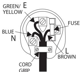
If a 13 Amp (BS 1363) plug is used, a 3 Amp fuse must be fitted, or if any other type of plug is used a 3 Amp or 5 Amp fuse must be fitted, either in the plug or adaptor, or on the distribution board.
INSTALLATION
Please take a moment to read these notes before installing your amplifier, they will enable you to get the best performance and prolong the life of the product.
The unit requires ventilation above and below. Do not situate it on a rug or other soft surface and do not obstruct the air inlet and outlet grilles on the underside and top cover. Do not place in an enclosed area such as a bookcase or in a cabinet.
This unit must not be exposed to dripping or splashing water or other liquids. No objects filled with liquid, such as vases, shall be placed on the unit. In the event, switch off immediately, disconnect from the mains supply and contact your dealer for advice.
Ensure that small objects do not fall through any ventilation grille. If this happens, switch off immediately, disconnect from the mains supply and contact your dealer for advice.
Do not route the power cable so that it can be walked upon or damaged by other items near it.
Electronic audio components have a running in period of around a week (if used several hours per day). This will allow the new components to settle down, the sonic properties will improve over this time.
It is recommended that when bi-amping, the same type power amplifiers are used.
This amplifier has been designed to be left in Standby mode when not in use, this will increase the life of the amplifier (this is true with all electronic equipment). If you do not intend to use this unit for a long period of time, unplug it from the mains socket.
To clean the unit, wipe its case with a moist, lint-free cloth. Do not use any cleaning fluids containing alcohol, ammonia or abrasives. Do not spray an aerosol at or near the amplifier.
These units are not user serviceable, never attempt to repair, disassemble or reconstruct the unit if there seems to be a problem. A serious electric shock could result if this precautionary measure is ignored. In the event of a problem or failure, please contact your dealer.
This unit should be installed on a sturdy, level surface. Due to stray magnetic fields turntables should not be located nearby due to interference.
REAR PANEL CONNECTIONS
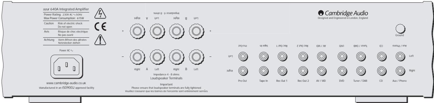
AC power socket
Once you have completed all connections to the amplifier, plug the AC Power Cable into an appropriate mains socket. The amplifier is now ready for use.
Loudspeaker connections
The 540A and 640A have two sets of Loudspeaker terminals on the rear panel, speakers A and B. Speakers A are the main speaker terminals, speakers B are the secondary switchable speaker terminals. Connect the wires from your left channel loudspeaker to the LEFT + & - terminals, and likewise the wires from the right channel loudspeaker to the RIGHT + & - terminals. In each case the red terminal is the positive output, and the black terminal is the negative input. Care should be taken to ensure no stray strands of wire are shorting speaker outputs together. Please
Note: This amplifier has been designed for use with loudspeakers that have a nominal impedance of between 4 and 8 ohms.
Please ensure that the speaker terminals have been tightened adequately to provide a good electrical connection. It is possible for the sound quality to be affected if the screw terminals are loose.
Pre amp outs
Connect these sockets to the inputs on an external Power Amplifier(s).
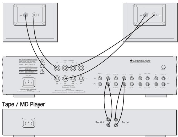
Tape mon
These sockets can be connected to a tape deck or to the analog sockets on a MiniDisc or CD recorder. Connect an interconnect cable from the recorder's Line Out sockets to the amplifier's Tape Monitor sockets. This
monitor doubles up as the standard tape/recording medium input.
Note: When connecting a source component that has both an input and output i.e. a tape recorder, the output of which should always be connected to the Tape Mon input. This will eliminate howlround if the wrong Input channel is selected.
Tape out
These sockets can be connected to a tape deck or to the analog sockets on a MiniDisc or CD recorder. Connect an interconnect cable from the Tape Out sockets of this amplifier to the recorder's Line In. Please note that this unit has two tape loops which have identical outputs.
CD/Tuner/DVD/AV/MD input sockets
These inputs are suitable for any 'line level' source equipment such as CD players, DAB or FM/AM tuners etc.
Aux/Phono input sockets
Connect any 'line level' source equipment to these sockets i.e. CD player or DAB tuner. Alternatively this particular input can be converted to a dedicated turntable if desired although to do this a Cambridge Audio PM01 Phono Module must be fitted. Please contact your Cambridge Audio dealer who can supply and install a phono stage to your amplifier.
These inputs are for analog audio signals only. They should not be connected to the digital output of a CD player or any other digital device.
Ground connection
If you are connecting a turntable to your amplifier then its ground wire should be attached to this point
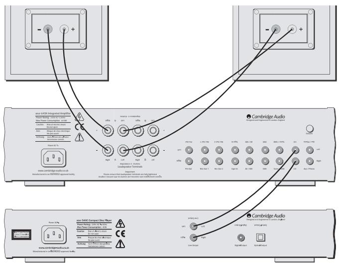
CONNECTING
When designing our amplifiers we have tried to include features that allow you to connect your system in various ways. The inclusion of features such as PRE-OUT and SPEAKER B connections mean that you can configure your system depending on your requirements. The following diagrams are designed to make connection easy.
Basic connection
The following diagram shows the basic connection of your amplifier to a CD player and a pair of loudspeakers.
Tape connection
The following diagram shows how to connect the amplifier to a tape recorder or other source with a record and monitor connection.
Please note that either of the tape loop outputs can be used (as they are both the same).
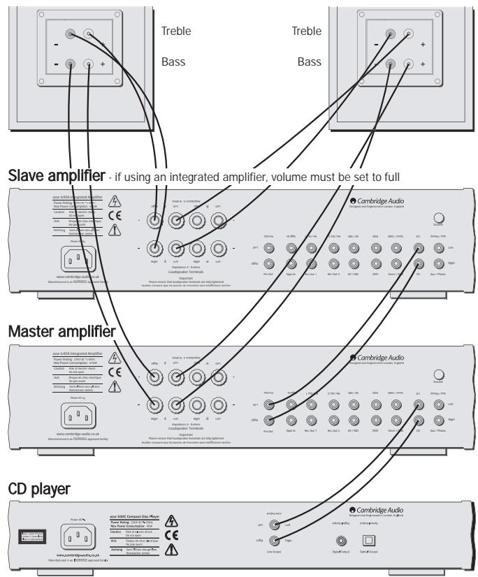
Bi-amping
The azur amplifiers are equipped with PRE-OUT sockets. If your loudspeakers have two sets of terminals then it is possible to bi-amp your system using a further power amplifier. Bi-amping uses two amplifiers to drive the bass and treble units in the loudspeakers independently, resulting in even greater clarity coupled with improved control and dynamics. An example of a bi-amp setup is illustrated in the diagram adjacent.
Please note that if using a second azur amplifier as the slave amplifier, any line input can be used to connect from the master's Pre-Out.
Using Speaker B connections
The Speaker B connections on the back of the amplifier allow a second set of speakers to be used, which could be for another room.
OPERATING INSTRUCTIONS
Cambridge Audio
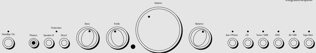
Standby/On
Switches the unit between Standby mode (indicated by dim power LED) and On (indicated by bright power LED). Standby is a low power mode where the power consumption is less than 10 Watts. The unit should be left in standby when not in use.
Headphone socket
Allows for the connection of headphones with a 14 " Jack plug connector. When the headphones are connected the loudspeaker relay is released switching off the output to the loudspeakers (Speakers A and B).
Speaker B on/off
Enables/disables the secondary set of speaker terminals on the back panel. This can be used for listening to an extra set of speakers in another room.
Please note that care should be taken when selecting if two loudspeakers are going to be used on each channel. If the combined resistance measured on the speaker terminals is too low the amplifier may not switch out of standby mode until a suitable load resistance is detected. For more information please see section on CAP5 protection system.
Note - When using two pairs of speakers each pair should be rated at least 6 ohms (or higher). 4 ohm speakers are not recommended when using more than one pair.
Direct
This control gives the audio signal a more direct path to the power amplifier stage of your amplifier, bypassing the tone control circuits for the purest possible sound quality.
Bass and treble tone controls
These controls allow subtle adjustments to the tonal balance of the sound. In the central position these controls have no effect. These controls only modify the sound through your loudspeakers and the Pre-Out sockets (where featured), they do not affect the signals sent through the Tape Out connections. With a well produced CD and a good system the tone controls are unnecessary and can be switched out. If the musical recording is of poor quality and/or the loudspeakers/surroundings are lacking it may be necessary to adjust the tone controls to compensate.
Volume
The Volume control increases/decreases the level of the sound from the outputs of the amplifier. This control affects the level of the Loudspeaker output, the pre amp output and the headphone output. It does not affect the Tape Out Connections.
It is advisable to turn the Volume control fully anti-clockwise before switching the amplifier on.
Balance
This control allows you to adjust the relative output levels of the left and right channels. In the central position the output from each channel is equal. This control only modifies the sound through your loudspeakers and the Pre-Out sockets (where featured), it does not affect the signals sent through the Tape Out connections.
Input selection push buttons
Push the appropriate input selection button to select the source component that you wish to listen to. The signal selected is also fed to the Tape Out sockets so that it may be recorded. The input should not be changed whilst recording, although the recorded signal can be checked using the tape input Tape monitor.
Tape monitor selection button
This control lets you listen to the output signal from a tape recorder or signal processor connected to the amplifier's Tape monitor sockets. When Tape monitor is selected, the source component chosen by the input selection push buttons continues to be routed to the Tape Out sockets for recording or processing.
Remote control operation/features
This Amplifier is supplied with a system remote control that operates both this amplifier and the Cambridge Azur CD players. The functions relevant to the amplifier are as follows:
Power - Switches the amplifier between Standby mode and On mode.
Mute - Mutes the audio (indicated by the input LED flashing).
Volume +/- The volume buttons increase and decrease the Volume of the amplifier output.
Input select - The five input select buttons and the Tape monitor select button are used to change the input source.
CAP5 - FIVE WAY PROTECTION SYSTEM
Cambridge Audio has developed a proprietry protection system to ensure reliability and a long life to its amplifiers. This protection system comprises of five main protection methods:
Intelligent clipping detection
CAP5 has the ability to detect when the amplifier starts to clip or overdrive its output, which can damage Loudspeakers, the amplifier power supply and most importantly degrade the sound. When CAP5 detects clipping the volume will be automatically nudged down until CAP5 detects an undistorted output (the volume is nudged down until the distortion is less than 2% which listening tests have shown is difficult to hear).
It is possible to disable only this feature by holding down the Standby button during power up (whilst plugging the unit into the mains power). The unit will indicate this by flashing the protection LED for several seconds. Disabling the clipping detection is not advised as this feature has been added to protect the amplifier.
Over temperature detection
CAP5 includes temperature detection which constantly monitors the heat generated by the output transistors. When the monitored temperature reaches a high level (suitably within the limits of the output devices) the amplifier will automatically switch into a fault mode (indicated by double flashing of the protection LED). The unit should ideally be left for 15 minutes in this state to cool down adequately. If the unit has not fully cooled down then the temperature may reach the limit soon after the amplifier is powered up.
If the Loudspeaker impedance is low the temperature of the amplifier may rise faster as the amplifier is working harder. If the amplifier is mounted in a cabinet or the ventilation slots are obstructed the over temperature detection may activate/reactivate after a short listening time.
Short circuit detection
During power up from standby or during input channel selection CAP5 performs a check on the Loudspeaker terminals to see if a short across the terminals has been accidentally introduced. If the resistance measured across the Loudspeaker terminals is too low the unit will stay in Standby mode until the fault has been removed and Power up is re-attempted.
DC detection
CAP5 offers Loudspeaker protection if the output of the amplifier goes to DC because of some internal fault. This is a rare fault although it could just save those expensive Loudspeakers.
If the amplifier is switched out of standby when the input signal to the amplifier is too high (with the current volume setting) the CAP5 system will detect this and reduce the volume to a suitable level.
Overvoltage/overcurrent detection
CAP5 offers V/I protection by constantly monitoring the output transistors to keep them working inside their Safe Operating Area (SOA). The SOA is a set of limits given by the output transistor manufacturer to ensure reliability. Many amplifier designers include V/I limiting in the
signal path which can degrade the signal by compressing dynamics. The CAP5 system operates outside the signal path and when triggered shuts down the amp rather than limits the size of the signal passing through the amp (signal compression). V/I protects the amplifier against short circuits on the speaker terminals during use.
| Indication | Fault/Remedy |
| Protection LED flashes for 4 seconds when unit attempts to come out of Standby mode. | CAP5 has detected that the resistance on the Loudspeaker terminals is too low. Check to see if there is a short circuit between the Loudspeaker terminals. Note: If the indication remains the same and multiple Loudspeakers are being used on each Loudspeaker output then please remove a pair and retry. If too many Loudspeakers are connected to any amplifier causing the Load resistance to drop too low the amplifier will overheat. CAP5 will detect this situation. If the indication remains the same with only one set of loudspeakers connected then there could possibly be a fault with one or both of the loudspeakers. |
| Unit has switched off during operation. Protection LED constantly double flashes. | CAP5 has detected a user related fault, the internal temperature of the output transistors has reached the over temperature limit. The unit is not damaged although it should be left for 15 minutes to cool down before being switched out of standby. |
| Unit has switched off during operation. Protection LED constantly flashes on and off in bursts of 4. | CAP5 has detected a user related fault, there maybe a short circuit between the loudspeaker terminals. Please check all Loudspeaker connections before attempting to switch unit out of standby |
| Unit has switched off during operation. Protection LED is on with a brief off flash. | CAP5 has detected a fault which requires the unit to be serviced. DC has been detected on the output of the amplifier which could damage the speakers. The amplifier is now unusable. Please switch off and contact dealer. |
TROUBLESHOOTING
There is no power
Ensure the AC power cord is connected securely.
Ensure the plug is fully inserted into the wall socket and is switched on.
Check fuse in the mains plug or adaptor
There is no sound
Make sure the unit is not in Standby mode
Check that source component is properly connected
Check that 'TAPE MON' is not switched on (unless tape input is required)
Check that your speakers are properly connected
If using Speaker B terminals check they are switched on
If channel LED is flashing turn mute off
There is no sound on one channel
Ensure that balance control is in the correct position Check speaker connections Check interconnects
There is a loud buzz or hum
Check turntable or tone arm for ground and connection lead fault
Ensure no interconnects are loose or defective
Ensure that your tape deck/turntable is not too close to the amplifier
Unable to make or play tape recordings
Check that TAPE MON and TAPE OUT have been connected correctly
There is weak bass or diffused stereo imaging
Ensure that speakers are not wired out of phase
Will not switch out of standby - protection LED flashing
Please see section on CAP5 protection system
Protection LED flashing
Please see section on CAP5 protection system (page 12)
SPECIFICATIONS
| 540A | 640A | |
| Power Output | 75W (into 4Ω) | 100W (into 4Ω) |
| 50W (into 8Ω) | 65W (into 8Ω) | |
| Max Power Consumption | 515W | 615W |
| Standby Power Consumption | 6W | 6W |
| THD (unweighted) | 1kHz < 0.009% | 1kHz < 0.005% |
| 20kHz < 0.09% | 20kHz < 0.07% | |
| Freq Response (-3dB) | 5Hz - 50kHz | 4Hz - 80kHz |
| S to N Ratio (unweighted) | 92dB | 92dB |
| Slew Rate (Into 8Ω) | 30V/uS | 50V/uS |
| Dimensions (HxWxD) | ||
| mm | 100 x 430 x 310 | 100 x 430 x 310 |
| Inches | 3.9 x 16.9 x 12.2 | 3.9 x 16.9 x 12.2 |
| Weight | ||
| kg | 7 | 7 |
| Lbs | 15.4 | 15.4 |
LIMITED WARRANTY
Cambridge Audio warrants this product to be free from defects in materials and workmanship (subject to the terms set forth below). Cambridge Audio will repair or replace (at Cambridge Audio's option) this product or any defective parts in this product. Warranty periods may vary from country to country. If in doubt consult your dealer and ensure that you retain proof of purchase.
To obtain warranty service, please contact the Cambridge Audio authorised dealer from which you purchased this product. If your dealer is not equipped to perform the repair of your Cambridge Audio product, it can be returned by your dealer to Cambridge Audio or an authorised Cambridge Audio service agent. You will need to ship this product in either its original packaging or packaging affording an equal degree of protection.
Proof of purchase in the form of a bill of sale or receipted invoice, which is evidence that this product is within the warranty period, must be presented to obtain warranty service.
This Warranty is invalid if (a) the factory-applied serial number has been altered or removed from this product or (b) this product was not purchased from a Cambridge Audio authorised dealer. You may call Cambridge Audio or your local country Cambridge Audio distributor to confirm that you have an unaltered serial number and/or you purchased from a Cambridge Audio authorised dealer.
This Warranty does not cover cosmetic damage or damage due to acts of God, accident, misuse, abuse, negligence, commercial use, or modification of, or to any part of, the product. This Warranty does not cover damage due to improper operation, maintenance or installation, or attempted repair by anyone other than Cambridge Audio or a
Cambridge Audio dealer, or authorised service agent which is authorised to do Cambridge Audio warranty work. Any unauthorised repairs will void this Warranty. This Warranty does not cover products sold AS IS or WITH ALL FAULTS.
REPAIRS OR REPLACEMENTS AS PROVIDED UNDER THIS WARRANTY ARE THE EXCLUSIVE REMEDY OF THE CONSUMER. CAMBRIDGE AUDIO SHALL NOT BE LIABLE FOR ANY INCIDENTAL OR CONSEQUENTIAL DAMAGES FOR BREACH OF ANY EXPRESS OR IMPLIED WARRANTY IN THIS PRODUCT. EXCEPT TO THE EXTENT PROHIBITED BY LAW, THIS WARRANTY IS EXCLUSIVE AND IN LIEU OF ALL OTHER EXPRESS AND IMPLIED WARRANTYES WHATSOEVER INCLUDING, BUT NOT LIMITED TO, THE WARRANTY OF MERCHANTABILITY AND FITNESS FOR A PRACTICAL PURPOSE.
Some countries and US states do not allow the exclusion or limitation of incidental or consequential damages or implied warranties so the above exclusions may not apply to you. This Warranty gives you specific legal rights, and you may have other statutory rights, which vary from state to state or country to country.
EINLEITUNG
Matthew Bramble Technical Director
INHALT
Einleitung. 16
Integrated Amplifier
Standby/On

Phones

Protection

per B Direct


Aux/Phono

CD

Tuner/DAB

DVD

AV/MD

Tape Mon

Standby/On
Specifications techniques 42
Garantie limitée 43
CONSIGNES DE SECURITÉ
Ground connection (Terre)
Please note that if using a second azur amplifier as the slave amplifier, any line input can be used to connect from the master's Pre-Out.
Integrated Amplifier
Standby/On

Phones

Protection

Direct


Aux/Phono

CD

Tuner/DAB

DVD

AV/MD

Tape Mon

Please note that if using a second azur amplifier as the slave amplifier, any line input can be used to connect from the master's Pre-Out.
Integrated Amplifier
Standby/On

Phones

Protection

Direct


Aux/Phono

CD

Tuner/DAB

DVD

AV/MD

Tape Mon

Matthew Bramble Technical Director
INDHOLD
Indledning 72
Please note that if using a second azur amplifier as the slave amplifier, any line input can be used to connect from the master's Pre-Out.
Integrated Amplifier
Standby/On

Phones

Protection

Direct


Aux/Phono

CD

Tuner/DAB

DVD

AV/MD

Tape Mon

De bas- of stereoweergave is verstrooid
COBMECTMOCn (89/336/EEC), KOrda ONo yCTaHO BHeIO
IcNoJIb3yeTcR CORlaCHO 3TOMy pyKOBoDCTBy IIN
noIb3OBATeJIy. Ia rapaHTnH enpepbIBHO
COBMECTIMOCTN 3TOI0 IN3DEJINIA DONXHbI NCIOJIb3OBaTbCA
IcknoHTeBHO npHaJnEeKHOCTN KOMpaHn Cambridge Audio n 06cnykBaHne DoJxHo 6bTb DOBepeHO KBaJInΦuNpObaHOMy
obcnykmbaioeMy nepcohany.

YCTAHOBKA
Ioxayncta, ydienite HEMHOROBpeMeHN, YTObI npOHTaTb 3TN pImeuaHnpeRedyCTAHOBKOi Bawaero ycInNTen, OHNI PO3BOnrT Bam oBeCneuTb HauNyUwne 3KcPnIyatauONHbIke KaueCTBa I npOJNtB JxN3Hb n3deJIIN.
YcTpoCTBO HUxJaTeCnB BeHTnIaum Cbepxu n CHN3y. He pacoNaarate He ro HA KOBpInke mIIN dpyroM MRAKON NOBePXRHOCTm, n He 3aTrpydHnIte DOCTyn K BXODHbIM OTBepCTnAM IN K peWetkam Dn BbIXOda BO3Dyxa Ha HNXHe pNOCKOTn HA BepXHe KpbIaKe. He YcTaHaBnBaIte ero B repMeTnHHe MeCTo TnPa KNHXHOrO ShkaFa a nn IaNka.
3To yctpoictBO He DoJnxHO PoBBepraTbCBA 03dEicTBHIO 6bpI3r HnnpoIHTOBdBi IIN DpynIX XnKIOCTe. He YcTaHaBnIbAitHe yctpoictBO HnKaKHe PpeDMtBI TnBa BA3, 3aONHeHHbIe XnKIOCTbIO. B Cnyae NOnaDaHnIB A Hero XnKIOCTn, HEmEdJeHNO BbIKIOuHTe yctpoictBO, OTCoeDHNITe OT 3NeKTPueCheKoi CETN IObpaNTecB K BaIeMy dInIepy dJIr nOlyeHn peKOMeHndaui.
CneiHTE 3a TEM, YTObI MEKNE ppeMeTbI He npOBaINBaNcB uepe3 BEHTINJIOHOHny peWteKY. Ecnn 3To npOn3ONoH, HEMeJNeHHo BvIKJIOnHTe yCTPOJCTBO, OTCoeDNHTE OT 3NeKTPnueckO cTeN I 6obatntcB K BAWE MyDnepy I nONyHeHHaPeKOMeHaDaun.
He npoklaabBaTe uHyp nHTaHn TaK, YTO6b Ha HrO MoTIn HaCTynTb UIN OH MO6blbIOBpeXKeH dpyHMn COeDHMMnpEeMeTaMn.
3NeKtpoHbIe 3ByKOBbIe KOMNoHEtbl DOnJXhbl npOITNO6KaTky B TeueHne PrimeMPOHOdON HeDJIe (ECNINNCnB3OaTByCTPOiCTBO NO HECKoBkY qacOB B DeH).3TO N03BOJNT HOBJM KOMNoHEtAM CTaBNI3pOBAbTaC, 3a 3OTNIEpHOd 3ByKOBbIe CBOJCTBa yNUyUaATcR.
Pn COBmecTHOM PnIMeHEnn DByx ycNInTeJe peKOMeHdyetc NcNoJIb3OBaTb ycNInTeJMoUHOCTN OJHOrTOJNa.
3TOT yCNlntelb 6bln pa3pa6oTaH c TaKIM paCyeTOM, qTO, KOrda OH He cnOJb3yETcT, To eTO MOxHO octaBnTb B pexime OxNiadHa, 3TO yBENmHT cPOK cNyXb yCNlnteN (3TO cnpabeDInBO dBcero 3NeKtPOHHORO oObOpDobAHn). Ecnbl BHe hamepeBaeteCe
MCNOB3OBaTb 3TO yCTpOCTBO B TEChHeN DINTEJbHOrO NepNoJa BpEMeH, TO BbIKIOHTe ERO I OTCoeDHNITE OT pO3eTKI 3NeKTPuYeCKO CETn.
UTo6bI OUnCTnTb yCtpoNCTBO, npOtnpaIte erO BnaXHO TkaHbIO 6e3 BOpCInOH. He nCNoJIb3yIte HnKaKHX XnIkoCTe Inra YnCTKn, CoedepaJxCNPT, aMmNk AnI abp3aNbIb. He paCnblIaTe a3pO30nb Ha Bau yCnNTeBnn B6Nn3H Hero.
3To n3dJIeIne He noJnEXKIT o6cnykUbaHIO NOIb3OBATeJeM; HIKoIa npi BO3NHKHOBEHIM HEnCnpaBHOCTHe N IbTaIaTIEcb Camn IpOn3BOIDtB peMOHT, pa3bOpAIBN INI PEKOHCTpyuPObaTB yctPoIcTBo. EcnI 3TN npEynpexKaIoUme Mepbl INHOpNpyOTcR, TO BO3MOXeH cepbe3HbI 3JIekTPOsOK. B cnyae BO3NHKHOBEHIN HEmCnpaBHOCTN nI IOBpeJDeHIN, POkaNyIcTA, o6paTntEc K BaWemy dInpey.
3To yctpoCTBO DoJNkHO pa3Meuatabca Ha ycTOnyHBo,POBHO NOBepxHOctn. BcneCTBne HAnHHa 6nyJdaOuHm MarHHTbIX noneH, BO m36eXahne BpeHOro BnHnHn He cIeMyet pacnonarTaB No6JIIN3OCTn nponpbrBaTeB JdnnactnHok.
ПОДСоЕДИЗЕНЯ HA 3АнHeI ПАHEЛN
Pa3bem NITaHn O T cTeN nepemehHoro ToKa (AC)
Pcne TOrO, KaK BbI 3aBepuHn BCE PdKnLIOeHn K yCunntTeIO, BKIOHTeU Hpy nTahnK C cTeN peMeHHoTO kAc) B nDxOnduy IO p03eTK 3JeKTPnHeckn CETn. Tepeh yCuNTInel roTOB K Icnons3OBAHIO.
IopKJIoueHne rpoMkoROBOpnteJei
YcHnnteIN 540A n640A hmeoT ha3aHnei naHEn IBa Habopa pa3bEmOB dIy DInHAMKOB, DInHAMKn A n B. DInHAMKn A - 3TO KJIEMMb OCHOBhX bINHAMKOB, DInHAMKn B 3TO pa3bEmbl BToPnHOrO NpOKIIuOaEMORO DInHAMKNa. POkNIOauTe npOBoA ot DInHAMKa Bawero JeBOrO KAhana K KJIEMMe "LEFT + &", n aHAnOriuHO npOBoA ot DInHAMKa BaWero npABOrO KAhana K KJIEMMe "RIGHT + &".B KaKdOM cNyae KJIEMMa KPachORO ZcBeta - 3TO pONOXITeBHyB BxOD n KJIEMMa YepHOrO ZcBETA - 3TO pONOXITeBHyB BXOD. CJeDyET cNeDnTb 3A TeM, Tc0bbl POBoDNIK MHOxKnIbHO rpoOBa He 3AmKHyn HAKOpOTKO BIXOJb DInHAMKOB.
YyTtne, noXanyIcta: 3ToT ycHnInTeB 6bIb pa3pa6OtaH dIra NCIOJIb3OBAHnC DnHaMnKaMn C HOMnHaNbHbIM cOpOTNBJeHnEM OT 4do8 OM.
IOnkaJyNCTa, npOBepbTe HaDEXHOCTb 3aTAXKn KLEMM DINHAMIKOB dHnObeCneHcHn XPOoIeero 3NeKTPnueckoro CoedInHeHn. BnONHe BO3MOxHO, YTO Cna6aB 3aTAXKa BnHTOB KLEMM MOKET NOBJIaRb H KaYecTBO 3ByaHn.
Pre amps outs (BbIXOdbI npedBapntelbHoro ycnlnte)
IopKlIOaJIte 3TN 3axkIMbIK BXOdAM BHeUHero yCUNITeJIe(e) MOUHOCTN.
Klēmmbl "Tape mon"
3Tn 3axmbl MoXHO NOIcOeINHATb K JIeHTOCHOMy MaHHToFOHy IINK aHaIOrOBbIM 3axmam yCTpOCTBa Tnna MiniDisc IINI nnIuSyJero CD-
ДиCKOBODa. ПОдКлIOUанTe COeINHITeNbHbI Ka6eIb OТ KJIeMM "Line Out" (ПИнЕнБИВ BByXOD) ПИшУшERO yctpoiNCTBa K 3azKIMAM "Tape Monitor" (MOHNTOP JIHTOCHORO MaHNToFOHa) yCUNITEЯ. 3OT MOHNTOP cIyJXHT Iy6NtOKAMTOB XOJa OBuHOrO JIHTOCHORO MaHNToFOHa IIN YcTPOIcTBa 3aIncn.
Ппмачин: Пп поклioчehин КИСТОУнКИ, ИМeIOUшЕМИ BxOD, И ВьXOD,TO eCTb K JLEHTOHOMM MARHITOnOFOH,ERO bVbOД BCERDAdoJIKeH COeINHATbCS C BXoDM "Tape Mon". 3To nO3BOJNTnCKIQUHTb rydeHne B Cnyae HeBepHOrOB BvIbOpa BXoDHorO KaHana.
Tape out (BbIXoJ IeHTOuHOro MaHHToΦoHa)
3Tn 3aXIMbl MoKHO NIOcOeHNrHb K JeHToHOMy MaHHToFOHy IIN K aHAnorOBbIM 3aXIMAM yCTPOiCTBa Tnna MiniDisc IIN NII NIIuSyUeero CD-DNCKOBODa. IOnkJIouaIte CoeHNITeBbI KAbEnb OT KJIeMM "Tape Out" 3TOrO yCNIITeR N 3aXIMAM "Line In" (IINHeNbI BxOd) NIIuSyUeero yCTPOiCTBa. Obpatne TBHIMAHHe Ha To, YTO DaHnHO eYCTPOiCTBO IMeET DBe NTIN JENHtI, IMEIOUX ODNHaKOBbIe BByXObl.
BxOdHbIe KJIeMMbI CD/Tuner/DVD/AV/MD
3TN BxOdbI BIAJTOC pIOXIOAUIIMM IJI NIOB0rIO CTOHNKA CINHANA TUNa "line level" (yoboeb cHnHaBA b IINH), aHAnoTnHOrO CDnnEepam, TIOHePAM DAB uNf FM/AM n dp.
Bxodhbie KneMMbI Aux/Phono
Поdkлioчайte к 3ТИМ 3axIMamЛIOБОИ NCTOCHNK CnHnAл TиNA "line level", HapnIMeP: CD-нлЕир Ип.TоHep DAB.ВkaueCTbe aIbTepHaTnBbl, пп Xжеланг 3ТOT cneцфческь BXOD MOxHOnCNoIb3OBAtB Дд ПОДКЛIOЧENH�poINrplBateл, npaBda, ДЯЗТOTOnpiDTeC yctahOBInTB 3ByKOBOМoDyIb PM01 KMpanHn Cambridge
Audio. IoxanyuCTa, obaTInTeCb K Bauwemy dInnepy KOMNaHm Cambridge Audio, kOtboty cMoXeT noObpaTb N do6aBnTb 3ByKoBoi KaKaad K Bauwemy ycInnTeJIo.
3Tm BXObI npedHaNaeHbI ToNBo IOnAnAoRObBix ayDIO cnHaoN. Ix HeJb3n PoKnIouaTb K uΦpOBomy BbxOy CDJIneepa Hnn IIO6oR drpyoro uΦpOBoro yctPoIcTBa.
IcnoJIb3OBAHnE BbIBoIDOB "Speaker B" (Динамнк B)
3aXnMbI "Speaker B" Ha 3aJHNe CTENHe YcUNITeIN JONYCKaOT npIMEnHe NTOBOPo HbOpa DInHAMKOB, KOTOpbIE MOrYT HaxOJNTbcB B dpyro kOMHate.
Integrated Amplifier
- Standby/On

Phones

Protection

Direct


Aux/Phono
CD
Tuner/DAB

DVD

AV/MD

Tape Mon

Standby/On (PexkIM oXnIaHnB/KKIOueHo)
3TOT nepeknoateIb nepeBODNT ycTpoCTBO n3 peXIMa OxNdaHn BO BKIOUeHnOE CoCtOHe. PpI3HakOM 3tNx DByx CyHKnC JcYXnT HINKATOpHb CND. PpN BKIOUeHn YCTOPOCTBa OH RPKO CEBTNCR, B pEXnme OxNDAHn INTEHCMBHOCTB CBeEHN yMeHbAaETCA BDOE.
Pa3bEmДЯHayshnKOB
3T0t pa3bem N03BOJAE TNDKIOHATb HayuHNIK C KpyrIbIM UTbIpbKOM dAmetpa 14 .Pnp NDKIOUeHm HuyuHNIKOB pene DnHaMKNOB OTKnIOaET cINHAN Ha bYXode dInnAMIKOB (DInnAMIKN A nB).
Speaker B on/off (Включени/OTКлючени ДиHamika B)
Ipaet/OTKIOUaET CnHAI HA BTOpHbI Hb6Op BbIOBOB DnHaAMNKOB Ha 3dHei cTeHKe. OHN MOrT pIpmMeHtcbI dJIPOcNHyBaHInB V COcEdHei KOMHATE nPi NOMOu DiONOHHTeBHOr HabOp DaHmIKoB.
Ioxayncta, yuTte, yTO cneDyET 6bITb octopoxhblm npn IcnoIb3OBAHIN DByX DNHAMIKOB HA KaJdOM n3 KaHaNIOB. Ecnn o6uee conpOTNBENHe, INMepHEMOE Ha BbIOJAX DNHAMIKOB, CInNkOM Mano, To yCNIHTeB MOKeT He nepeKJIIOUaTBcN 3PexIMa OxNJaHnDo tex nop, NOKa cOpOTNBENHe Harpy3Kn He cTaHET npNeEMMeMb. BoJe e noDpo6NaH INHcpMauaŋ pRbeDeHa B pa3dene: 3aunTHa nCtema CAP5.
PpimMeaHne - Pn nCNoIb3ObaHmN DByx nap DnHaMnKOB KaXdA npa doJoxHa IMeTb cOnpOTNBLeHne, no MeHbSeM Mepe, 6 OM (nnn 60Ble). KOrda nCNoIb3yETc 6oone e OHOJ npabl, He peKoMeHdyetc pImMeHrTa DnHaMnKc C cOnpOTNBLeHem 4 Oma.
Direct (PpamOn npTb)
3OTOr opraH ynpabennnpeooctabre aydno ciHany 60one npramOyntbK CTynen Hycnene MoHocCTn Bawero ycInTeN, oXbOna cENKoHTPOnTo ToHa nOBecneueHn Han60one NcTcTO RaCteBa 3Byka.
YnpabJIeHne 6acamn N BbICOKMm TOHAMN
3TN oprahbI ynpaBJIeHn I03BOJHOT BblONHrTb yTOHcEHNbI HeacTpOKn ToHaBHO 6aHAnca 3ByKa. B cHTpAJIbHOM nonOKeHnI 3TN peryIaTOpbI He OKa3bIbAOT HnKAKoD DeCTNB. 3TN peRyIaTOpbI NlMb MoINPhiUpyOT 3ByaHHe BaWix NdHAMIKOB n CnIHaNbI Ha BxOJNbIX 3aXmKmPpeBaPntEhBO YcINITeY "Pre-Out" (npi Hx HAInH), OHI He OKa3bIbAOT BnIAHn HA CnIHaNbI, NocBlaAeMbteYepe3 CoeINHeHn "Tape Out" (BbIXoJLeHTOHRo MArHToTOPhOA). EcnI KOMnAkrT-DnCK n CnCTema IMeOT BILCOKoe KaCteBO, TO peRyIaTOpbI ToHa He HuxKnI MOrYT b6tB OTKJIooHcE. EcnI Ke KaCteBO My3bIKAJIbHO 3aInCn Hn3Koe n/INcEtB HeDOCTATKn Y dINHAMKOB/O6bEMHORO OkpyKeHn, TO peryIaNPOBkTA ToHa MOKeT NOHaDo6NtcbS.
Volume (PpomKocTb)
Perylantop "Volume" (Pomkoctb) yBelenuHbaeT/ymEnblaaet ypoBeHb 3Byka Na BblxOax ycnInTeNn. 3OT0 perylantop Bo3dEiCTBEy H aPoBeHb BblXoHOrO CnHnana DnHnAMKa, npEdBaPntelHoBFO yCnHtEnn N HayuHnKOB. OH He Oka3bIbaeT BImHHa Na CnHaN Ha KJIemMax "Tape Out".
PekomehyetcnaepB BKIOUeHnEM ycINITaI NOBEPHyb pyky peYyIopTa "Volume" (PpOMKoCTb) do OTka3 npOTNB yacOBN CTpeJIKN.
Balance (Баланс)
3TOT peryIaTOp no3BONIeR Bam hactpIaBaTb OTHocntIbIhIe BbIXoIbIe yOBNH IeBOrO IIpaBOrO KAnAIOB. B CEHTPaNbHOM NOnOKeHN yOBNH MoIOCTn Ha BixOe KaKdORo KaHana paBhl. 3TOT peryIaTOp BIIraTe RIMb Ha MOIOCTb 3ByKa BaIwN dINHaMikOB bIXoIDbIX 3aJIMOB "PreOut" npEBArtpeBHO rCINITe (ecn OH nMeIOTc), OH He Bo3deIcTByET Ha CInrHaIbI Ha 3aJIMax "Tape Out".
Haxmhbie KhoNk BbIbopa BxOob
Haxkatahe Ha COOTBeTCTBlyOuIy KHNkY BbIbopa BxOHDoro CnHaIa N03BOJrAeT BbIbapb TOT BXoHOn KOMNoHEnT, KOtOpB bBy XeJaTe
cnyaTb. Bby6paHbI CNHaI TAKKe NOdaETc H a3axMbI "Tape Out", cTO NO3BONAEt Xx 3aINCbIBaTb. B TceHHe 3aINcH He CneDyET nepeKlIOuHaTb BXObl, XOTa 3aINCbIBaEmbl CNHaI MoXHO KOHTpOIIPOBaTb NocpeDCTBOM INCnOB3OBAHnJIeHToHOro BXOda "Tape monitor".
Haxmmha KhoNka BbIbopa "Tape monitor" (JeHTOuHbIMaHHToΦOH)
3TOT perynlaTOP npedoctabreBam BO3MOXHOCTb PpocnyuBaTb BbIXoHNO CINHAN OT JeHTOCHORO MArHITOCOHA INN CINHAnbHOrO npoceccopa, noKIOUeHHoro K 3axkMam "Tape monitor" ycInntenra. Korda BbIpaan "Tape monitor", BbIpaHHb nyTeM haxaTnR HaxmHBix KHNOK, BXoHNO KOMNoHEHCT OCTaETcN IOKIOUeHHbIM K 3axkMam "Tape Out" dnia ceJe 3aIncn n o6pa60TKn.
IcnoJb3ObaHne dNCTaHcNoHHOro nylbTa n erO cyHKcnn
3TOT ycnntenb noctabIaTeC C cnCTeMoI dNCTaHIOHOHRO ynpaJIeHHK, KOtOpA KoTHpOJIpyET KAK 3TOT ycnntenb, TAK I CD- neBepi cepn Cambridge Azur. Hxke nepueNCHeHb Han6oJIe BaxHbIe fynHcun ycnntenl:
PpOBepbTe HaJeXHOCTb NcnpaBHOCTb COeHHeHn
V6eBtBcTb TOM,TOBa IaHToHnOHHMaHrHToHOn HIn pOnrPbIbATEJB He YCTaHOBHeIb CImiKOM 6bn3K O yCINNTENIO
Helen3aannscbIbTaHaJeHTyIINIpOONrpBbTa3annc
PpOBepbTe npabNtBnOToCoeHHeHnKJIeMM "TAPE MON" n "TAPE OUT"
CnIuKOM CnIa6bI HN3KOAcTOTHbI CNrHaJI pa3MbIToe cTepeo n3O6paXeHne
Y6eIITecB NpaBnJIbHOCTN pa3npOBKn DnHaMVKOB
He npocxodnt nepekIIOueHne n3 peKIma OXnDaHna - Mraet CND 3aunTbI
Poxayncta,cm.pazd:3auntharcnCTemaCAP5
Miraet CNД 3aunTbI
Ioxayncta,cm.pa3d:3aunthnaCnCTemaCAP5(ctp.12)
XAPAKTEPNUCTUKN
- About this amplifier
- Now we invite you to sit back, relax and enjoy!
- CONTENTS
- SAFETY PRECAUTIONS
- Checking the power supply rating
- Plug fitting instructions (UK only)
- INSTALLATION
- REAR PANEL CONNECTIONS
- AC power socket
- Loudspeaker connections
- Pre amp outs
- Tape mon
- Tape out
- CD/Tuner/DVD/AV/MD input sockets
- Aux/Phono input sockets
- Ground connection
- CONNECTING
- Basic connection
- Tape connection
- Bi-amping
- Using Speaker B connections
- OPERATING INSTRUCTIONS
- Standby/On
- Headphone socket
- Speaker B on/off
- Direct
- Bass and treble tone controls
- Volume
- Balance
- Input selection push buttons
- Tape monitor selection button
- Remote control operation/features
- CAP5 - FIVE WAY PROTECTION SYSTEM
- Intelligent clipping detection
- Over temperature detection
- Short circuit detection
- DC detection
- Overvoltage/overcurrent detection
- TROUBLESHOOTING
- There is no power
- There is no sound
- There is no sound on one channel
- There is a loud buzz or hum
- Unable to make or play tape recordings
- There is weak bass or diffused stereo imaging
- Will not switch out of standby - protection LED flashing
- Protection LED flashing
- SPECIFICATIONS
- LIMITED WARRANTY
- EINLEITUNG
- INHALT
- CONSIGNES DE SECURITÉ
- Ground connection (Terre)
- INDHOLD
- De bas- of stereoweergave is verstrooid
- YCTAHOBKA
- ПОДСоЕДИЗЕНЯ HA 3АнHeI ПАHEЛN
- Pa3bem NITaHn O T cTeN nepemehHoro ToKa (AC)
- IopKJIoueHne rpoMkoROBOpnteJei
- Pre amps outs (BbIXOdbI npedBapntelbHoro ycnlnte)
- Klēmmbl "Tape mon"
- Tape out (BbIXoJ IeHTOuHOro MaHHToΦoHa)
- BxOdHbIe KJIeMMbI CD/Tuner/DVD/AV/MD
- Bxodhbie KneMMbI Aux/Phono
- IcnoJIb3OBAHnE BbIBoIDOB "Speaker B" (Динамнк B)
- Standby/On (PexkIM oXnIaHnB/KKIOueHo)
- Pa3bEmДЯHayshnKOB
- Speaker B on/off (Включени/OTКлючени ДиHamika B)
- Direct (PpamOn npTb)
- YnpabJIeHne 6acamn N BbICOKMm TOHAMN
- Volume (PpomKocTb)
- Balance (Баланс)
- Haxmhbie KhoNk BbIbopa BxOob
- Haxmmha KhoNka BbIbopa "Tape monitor" (JeHTOuHbIMaHHToΦOH)
- IcnoJb3ObaHne dNCTaHcNoHHOro nylbTa n erO cyHKcnn
- Helen3aannscbIbTaHaJeHTyIINIpOONrpBbTa3annc
- CnIuKOM CnIa6bI HN3KOAcTOTHbI CNrHaJI pa3MbIToe cTepeo n3O6paXeHne
- He npocxodnt nepekIIOueHne n3 peKIma OXnDaHna - Mraet CND 3aunTbI
- Miraet CNД 3aunTbI
- XAPAKTEPNUCTUKN
Brand : CAMBRIDGE AUDIO
Model : AZUR 540A
Category : Integrated amplifier