USER MANUAL AZUR 851A CAMBRIDGE AUDIO
Your music + our passion
Contents
Introduction 2
Important safety instructions 3
Limited warranty. 4
Rear panel connections. 5
Front panel controls. 6
Remote control. 7
Connections. 8
Operating instructions 9
Amplifier setup 10
CAP5 - Fireway protection system 12
Custom installation (C.I.) use 13
Technical specifications. 13
Troubleshooting 13
Make sure you register your purchase.
Visit: www.cambridge-audio.com/sts
By registering, you'll be the first to know about:
Future product releases
- Software upgrades
- News, events and exclusive offers plus competitions!
This guide is designed to make installing and using this product as easy as possible. Information in this document has been carefully checked for accuracy at the time of printing; however, Cambridge Audio's policy is one of continuous improvement, therefore design and specifications are subject to change without prior notice.
This document contains proprietary information protected by copyright. All rights are reserved. No part of this manual may be reproduced by any mechanical, electronic or other means, in any form, without prior written permission of the manufacturer. All trademarks and registered trademarks are the property of their respective owners.
Copyright Cambridge Audio Ltd 2012.
Cambridge Audio and the Cambridge Audio logo are trademarks of Cambridge Audio.
Other brands mentioned are trademarks of their respective owners and are used for reference purposes only.
Cambridge Audio's policy of continuous improvement means design and specification may change without notice.
Introduction
Thank you for purchasing the Azur 851A Class XD Integrated Amplifier. The 8 series range is fundamental to our commitment to the continual development of the Azur range. We hope that you will appreciate the results and enjoy many years of listening pleasure from it. Like all Cambridge Audio products, the 851A adheres to our three core principles - stunning performance, ease of use and incredible value.
The 851A features our unique proprietary amplifier topology; Class XD™, designed to eliminate crossover distortion at low signal levels.
By actively displacing the crossover point this technology creates a region of pure Class-A operation where the crossover zone would otherwise be before moving into an enhanced form of Class B at higher levels. It should not be confused with Class AB, which gives a small area of Class A, but at the cost of higher distortion as soon as the signal level moves outside the AB area. Class XD circuitry not only removes crossover distortion from the zero-crossing point but also reduces distortion in the other parts of the amplifier's output range.
This 851A features our latest development of Class XD with many tweaks and enhancements from our on-going research resulting in our best sounding implementation to date.
A white paper on this patent pending technology is available on our website: www.cambridge-audio.com
Please note that because of the Class XD technology the 851A runs slightly warmer than a conventional Class B/AB amplifier and the ventilation slots on the top of the unit must not be obstructed.
A new balanced volume topology has been implemented for this model, controllable in 1 dB steps over most of the range, giving very fine control, an accurate logarithmic law and superbly accurate channel balance.
Input switching is by high quality gold contact relays.
The 851A features separate transformer secondaries for left and right channels, twin rectifiers and separate PSU's for dual mono operation of the left and right power amplifiers. A separate transformer supplies the preamp making the 851A effectively a Pre and Power amp combination in one box.
Balanced as well as unbalanced inputs are featured for Sources 1 and 2 giving optimal performance with equipment such as the matching 851C Upsampling CD player which features balanced outputs.
The casework combines massive structural rigidity with careful damping and control of acoustic resonance. An Azur Navigator remote control is also provided, giving full remote control of your amplifier in an attractive and easy to use handset.
Control Bus Input/Output, IR Emitter Input and RS232 control are featured making it easy to integrate the 851A into a Custom Installation system if desired.
Your amplifier can only be as good as the system it is connected to. Please do not compromise on your source equipment, speakers or cabling.
Naturally we particularly recommend models from the Cambridge Audio Azur range. These have been designed to the same exacting standards as this amplifier. Your dealer can also supply excellent quality Cambridge Audio interconnects to ensure your system realises its full potential.
Thank you for taking the time to read this manual; we do recommend you keep it for future reference.
南
Matthew Bramble,
Cambridge Audio Technical Director
and the 8-Series design team
Important safety instructions
For your own safety please read the following important safety instructions carefully before attempting to connect this unit to the mains power supply. They will also enable you to get the best performance from and prolong the life of the unit:
-
Read these instructions.
-
Keep these instructions.
-
Heed all warnings.
-
Follow all instructions.
-
Do not use this apparatus near water.
-
Clean only with a dry cloth.
-
Do not block any ventilation openings. Install in accordance with the manufacturer's instructions.
-
Do not install near any heat sources such as radiators, heat registers, stoves, or other apparatus (including other amplifiers) that produce heat.
-
Do not defeat the safety purpose of the polarized or grounding-type plug. A polarized plug has two blades with one wider than the other. A grounding-type plug has two blades and a third grounding prong. The wide blade or the third prong are provided for your safety. If the provided plug does not fit into your outlet, consult an electrician for replacement of the obsolete outlet.
-
Protect the power cord from being walked on or pinched, particularly at plugs, convenience receptacles and the point where they exit from the apparatus.
-
Only use attachments/accessories specified by the manufacturer.
-
Use with only the cart, stand, tripod, bracket, or table specified by the manufacturer, or sold with the apparatus. When a cart is used, use caution when moving the cart/ apparatus combination to avoid injury from tip-over.

-
Unplug this apparatus during lightning storms or when unused for long periods of time.
-
Refer all servicing to qualified service personnel. Servicing is required when the apparatus has been damaged in any way, such as the power-supply cord or plug having been damaged, liquid has been spilled or objects have fallen into the apparatus, the apparatus has been exposed to rain or moisture, does not operate normally, or has been dropped.
WARNING
- To reduce the risk of fire or electric shock, do not expose this unit to rain or moisture.
- Batteries (battery pack or batteries installed) shall not be exposed to excessive heat such as sunshine, fire or the like.
The unit is of Class 1 construction and must be connected to a mains socket outlet with a protective earthing connection.
The unit must be installed in a manner that makes disconnection of the mains plug from the mains socket outlet (or appliance connector from the rear of the unit) possible. Where the mains plug is used as the disconnect device, the disconnect device shall remain readily operable. Only use the mains cord supplied with this unit.
Please ensure there is ample ventilation. We recommend that you do not place the unit in an enclosed space; if you wish to place the unit on a shelf, use the top shelf to allow maximum ventilation. Do not put any objects on top of this unit. Do not situate it on a rug or other soft surface and do not obstruct any air inlets or outlet grilles. Do not cover the ventilation grilles with items such as newspapers, tablecloths, curtains, etc.
This unit must not be used near water or exposed to dripping or splashing water or other liquids. No objects filled with liquid, such as vases, shall be placed on the unit.

CAUTION
Risk of electric
shock.
Do not open.
flash with the arrowhead symbol within an equilateral intended to alert the user to the presence of un-insulated voltage' within the product's enclosure that may be of magnitude to constitute a risk of electric shock to persons.
The exclamation point within an equilateral triangle is intended to alert the user to the presence of important operating and maintenance instructions in the service literature relevant to this appliance.

WEEE symbol
The crossed-out wheeled bin is the European Union symbol for indicating separate collection for electrical and electronic equipment. This product contains electrical and electronic equipment which should be reused, recycled or recovered and should not be disposed of with unsorted regular waste.
Please return the unit or contact the authorised dealer from whom you purchased this product for more information.

CE mark
This product complies with European Low Voltage (2006/95/ EC), Electromagnetic Compatibility (2004/108/EC) and
Environmentally-friendly design of Energy-related Products (2009/125/ EC) Directives when used and installed according to this instruction manual. For continued compliance only Cambridge Audio accessories should be used with this product and servicing must be referred to qualified service personnel.

C-Tick mark
This product meets the Australian Communications Authority's Radio communications and EMC requirements.

Gost-R Mark
This product meets Russian electronic safety approvals.
FCC regulations
NOTE: THE MANUFACTURER IS NOT RESPONSIBLE FOR ANY RADIO OR TV INTERFERENCE CAUSED BY UNAUTHORIZED MODIFICATIONS TO THIS EQUIPMENT. SUCH MODIFICATIONS COULD VOID THE USER AUTHORITY TO OPERATE THE EQUIPMENT.

This equipment has been tested and found to comply with the limits for a Class B digital device, pursuant to Part 15 of the FCC Rules. These limits are designed to provide reasonable against harmful interference in a residential installation. This t generates, uses and can radiate radio frequency energy installed and used in accordance with the instructions, may mful interference to radio communications. However, there is see that interference will not occur in a particular installation.
If this equipment does cause harmful interference to radio or television reception, which can be determined by turning the equipment off and on, the user is encouraged to try to correct the interference by one or more of the following measures:
- Re-orient or relocate the receiving antenna.
- Increase the separation between the equipment and receiver.
- Connect the equipment into an outlet on a circuit different from that to which the receiver is connected.
- Consult the dealer or an experienced radio/TV technician for help.
Ventilation
IMPORTANT - The unit will become hot when in use. Do not stack multiple units on top of each other. Do not place in an enclosed area such as a bookcase or in a cabinet without sufficient ventilation.
Ensure that small objects do not fall through any ventilation grille. If this happens, switch off immediately, disconnect from the mains supply and contact your dealer for advice.
Positioning
Choose the installation location carefully. Avoid placing it in direct sunlight or close to a source of heat. No naked flame sources, such as lighted candles, should be placed on the unit. Also avoid locations subject to vibration and excessive dust, cold or moisture. The unit can be used in a moderate climate.
This unit must be installed on a sturdy, level surface. Do not place in a sealed area such as a bookcase or in a cabinet. Do not place the unit on an unstable surface or shelf. The unit may fall, causing serious injury to a child or adult as well as serious damage to the product. Do not place other equipment on top of the unit.
Due to stray magnetic fields, turntables or CRT TVs should not be located nearby due to possible interference.
Electronic audio components have a running in period of around a week (if used several hours per day). This will allow the new components to settle down and the sonic properties will improve over this time.
Power sources
The unit should be operated only from the type of power source indicated on the marking label. If you are not sure of the type of power-supply to your home, consult your product dealer or local power company.
This unit can be left in Standby mode when not in use and will draw <0.5W in this state. To turn the unit off, switch off at the rear panel. If you do not intend to use this unit for a long period of time, unplug it from the mains socket.
Overloading
Do not overload wall outlets or extension cords as this can result in a risk of fire or electric shock. Overloaded AC outlets, extension cords, frayed power cords, damaged or cracked wire insulation and broken plugs are dangerous. They may result in a shock or fire hazard.
Be sure to insert each power cord securely. To prevent hum and noise, do not bundle the interconnect leads with the power cord or speaker leads.
Cleaning
To clean the unit, wipe its case with a dry, lint-free cloth. Do not use any cleaning fluids containing alcohol, ammonia or abrasives. Do not spray an aerosol at or near the unit.
Battery disposal
Batteries may contain substances harmful to the environment. Please dispose of any discharged batteries with due consideration and in accordance with local environmental/electronic recycling guidelines.
Loudspeakers
Before making any connections to loudspeakers, make sure all power is turned off and only use suitable interconnects.
Servicing
These units are not user serviceable. Never attempt to repair, disassemble or reconstruct the unit if there seems to be a problem. A serious electric shock could result if this precautionary measure is ignored. In the event of a problem or failure, please contact your dealer.
Limited warranty
Cambridge Audio warrants this product to be free from defects in materials and workmanship (subject to the terms set forth below). Cambridge Audio will repair or replace (at Cambridge Audio's option) this product or any defective parts in this product. Warranty periods may vary from country to country. If in doubt consult your dealer and ensure that you retain proof of purchase.
To obtain warranty service, please contact the Cambridge Audio authorised dealer from which you purchased this product. If your dealer is not equipped to perform the repair of your Cambridge Audio product, it can be returned by your dealer to Cambridge Audio or an authorised Cambridge Audio service agent. You will need to ship this product in either its original packaging or packaging affording an equal degree of protection.
Proof of purchase in the form of a bill of sale or receipted invoice, which is evidence that this product is within the warranty period, must be presented to obtain warranty service.
This Warranty is invalid if (a) the factory-applied serial number has been altered or removed from this product or (b) this product was not purchased from a Cambridge Audio authorised dealer. You may call Cambridge Audio or your local country Cambridge Audio distributor to confirm that you have an unaltered serial number and/or you made a purchase from a Cambridge Audio authorised dealer.
This Warranty does not cover cosmetic damage or damage due to acts of God, accident, misuse, abuse, negligence, commercial use, or modification of, or to any part of, the product. This Warranty does not cover damage due to improper operation, maintenance or installation, or attempted repair by anyone other than Cambridge Audio or a Cambridge Audio dealer, or authorised service agent which is authorised to do Cambridge Audio warranty work. Any unauthorised repairs will void this Warranty. This Warranty does not cover products sold AS IS or WITH ALL FAULTS.
REPAIRS OR REPLACEMENTS AS PROVIDED UNDER THIS WARRANTY ARE THE EXCLUSIVE REMEDY OF THE CONSUMER. CAMBRIDGE AUDIO SHALL NOT BE LIABLE FOR ANY INCIDENTAL OR CONSEQUENTIAL DAMAGES FOR BREACH OF ANY EXPRESS OR IMPLIED WARRANTY IN THIS PRODUCT. EXCEPT TO THE EXTENT PROHIBITED BY LAW, THIS WARRANTY IS EXCLUSIVE AND IN LIEU OF ALL OTHER EXPRESS AND IMPLIED WARRANTYES WHATSOEVER INCLUDING, BUT NOT LIMITED TO, THE WARRANTY OF MERCHANTABILITY AND FITNESS FOR A PRACTICAL PURPOSE.
Some countries and US states do not allow the exclusion or limitation of incidental or consequential damages or implied warranties so the above exclusions may not apply to you. This Warranty gives you specific legal rights, and you may have other statutory rights, which vary from state to state or country to country.
For any service, in or out of warranty, please contact your dealer.
Plug Fitting Instructions (UK only)
The cord supplied with this appliance is factory-fitted with a UK mains plug fitted with a 5-amp fuse inside. If it is necessary to change the fuse, it is important that a 5-amp fuse is used. If the plug needs to be changed because it is not suitable for your socket, or becomes damaged, it should be cut off and an appropriate plug fitted following the wiring instructions below. The plug must then be disposed of safely, as insertion into a mains socket is likely to cause an electrical hazard. Should it be necessary to fit a 3-pin BS mains plug to the power cord, the wires should be fitted as shown in this diagram. The colours of the wires in the mains lead of this appliance may not correspond with the coloured markings identifying the terminals in your plug. Connect them as follows:
The wire which is coloured BLUE must be connected to the terminal which is marked with the letter 'N' or coloured BLACK.
The wire which is coloured BROWN must be connected to the terminal which is marked with the letter 'L' or coloured RED.
The wire which is coloured GREEN/YELLOW must be connected to the terminal which is marked with the letter 'E' or coloured GREEN.
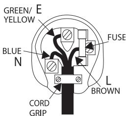
If a standard 13-amp (BS 1363) plug is used, a 5-amp fuse must be fitted or, if any other type of plug is used, a 5-amp fuse must be fitted, either in the plug or adaptor, or on the distribution board.
Rear panel connections
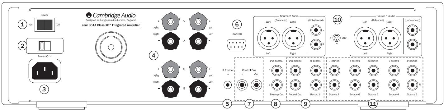
① Power On/Off
Switches the unit on and off.
② Mains Voltage Selector Switch (CU version only)
Switches the 851A mains voltage between 100V and 115V.
Note: Intended for use by a professional installer or Cambridge Audio retailer only.
③ AC power socket
Once you have completed all connections to the amplifier, plug the AC power cable into an appropriate mains socket then switch on. Your amplifier is now ready for use.
4 Loudspeaker terminals
Two sets of loudspeaker terminals are available, A (main loudspeaker terminals) and B (secondary loudspeaker terminals). Both sets of speakers can be turned on and off independently. Connect the wires from your left channel loudspeaker to the Left + & - terminals, and the wires from the right channel loudspeaker to the Right + & - terminals. In each case, the red terminal is the positive output and the black terminal is the negative output.
Care should be taken to ensure no stray strands of wire short the speaker outputs together. Please ensure that the loudspeaker terminals have been tightened completely to provide a good electrical connection. It is possible for the sound quality to be affected if the screw terminals are loose.
Note: When using two pairs of speakers, use speakers with a minimum nominal impedance of 16 ohms.
⑤ IR (Infrared) Emitter In
Allows modulated IR commands from multi-room systems to be received by the amplifier. Commands received here are not looped out of the Control Bus. Refer to the 'Custom installation' section for more information.
⑥ RS232C
The RS232C port allows external serial control of the 851A for custom install use. A full command set is available on the Cambridge Audio website at www.cambridge-audio.com. This port can also be used by Cambridge Audio service personnel for software updates.
⑦ Control Bus
In - Allows un-modulated commands from multi-rooms systems or other components to be received by the unit.
Out - Loop out for control bus commands to another unit. Also allows the 851A to control some Cambridge Audio units.
(8) Preamp Out
Connect these sockets to the inputs on an external power amplifier(s) or active subwoofoers etc.
⑨ Rec In
Connect to a tape deck or to the analogue output sockets on a MiniDisc, portable digital music player or CD recorder using an interconnect cable from the recorder's Line Out sockets to the amplifier's Rec In sockets.
The Rec input circuit of the 851A is a "monitor" type, different from the other 7 inputs. For the 7 normal inputs, the source selected for listening will be sent out of the Rec Out for recording. The source currently being listened to and (optionally) recorded is then shown on the front panel display.
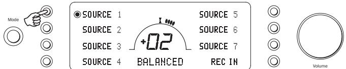
However, when Rec In is selected a solid circle will appear beside REC IN indicating that the Rec input is now being listened to with a different source being sent out of the Rec Out for recording. The recording source is also shown by a solid circle by the selected input and can be changed by pressing the other source buttons.
To switch Rec input off, simply press the 'Rec In' select button again, toggling this function off.
This feature is most useful when using 3-head analogue cassette decks which allow the signal being recorded to be played back live off tape (via a 3rd head) whilst it is simultaneously recorded. It is then possible by toggling the Rec input on and off to compare directly in real time the original and recorded signal so that adjustments to the recording parameters of the tape machine can be made (consult the manual of your 3-head analogue cassette deck for full details).
Rec Out
For connection to the line level inputs of Tape Recorders or other analogue recording apparatus.
These inputs feature either unbalanced (phono/RCA) or balanced (XLR) connections. The balanced connection is the higher quality option and can reject noise and interference in the cable when used with other equipment that supports this function. An XLR connector is wired Pin 1 - Ground; Pin 2 - Hot (inphase); Pin 3 - Cold (phase-inverted).
Note: Repeatedly pressing the Source 1 or Source 2 buttons on the front of the unit will toggle these inputs between 'Balanced' and 'Unbalanced' source inputs.
11 Sources 3-7
These inputs are suitable for any 'line level' source equipment such as CD players, DAB or FM/AM tuners etc.
Note: These inputs are for analogue audio signals only. They should not be connected to the digital output of a CD player or any other digital device.
Front panel controls
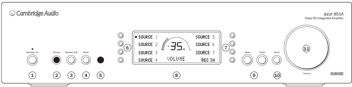
① Standby/On
Switches the unit between Standby mode (indicated by dim power LED) and On (indicated by bright power LED). Standby is a low power mode where the power consumption is less than 0.5 Watts. The unit can be left in Standby mode when not in use.
Note: As default the 851A ramps the volume up or down when switched on and when going into Standby mode. This feature can be turned off if desired; please refer to the 'Amplifier setup' section of this manual for more information.
② Phones
Allows for the connection of stereo headphones with a 14 Jack plug. Headphones with an impedance of between 32 and 600 ohms are recommended. When the headphones are connected, the loudspeaker relays are released switching off the output to the loudspeakers (speakers A and B).
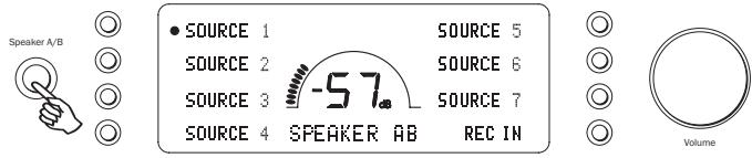
③ Speaker A/B
Press to scroll through the speaker sets connected to the loudspeaker terminals on the back panel (speaker sets A, B or A and B). This can be used for listening to an extra set of loudspeakers in another room.
Please note that care should be taken when choosing speakers if two loudspeakers are going to be used on each channel. If the combined resistance measured on the loudspeaker terminals is too low the amplifier may not switch out of Standby mode until a suitable load resistance is detected. For more information refer to the CAP5 section of this manual.
Note: When using two pairs of speakers, use speakers with a minimum nominal impedance of 16 ohms.
④ Mode
Press to switch between Volume and Balance modes. Press and hold to enter the 851A System Configure menu.
⑤ Infrared sensor
Receives IR commands from the supplied Azur remote control. A clear unobstructed line of sight between the remote control and the sensor is required.
Push the appropriate input selection button to select the source component that you wish to listen to (highlighted by a solid circle on the display). The signal selected is also fed to the Rec Out sockets so that it may be recorded. The input should not be changed whilst recording (but the recorded signal can be checked using the Rec input).
Note: Repeatedly pressing the Source 1 or Source 2 buttons will toggle these inputs between 'Balanced' and 'Unbalanced' source input.
⑧ Display
LCD used to control the 851A. Please refer to the 'Operating instructions' and 'Amplifier setup' section of this manual for more information.
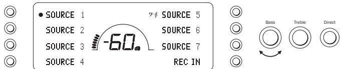
Bass and Treble
Press to release and rotate to allow subtle adjustments to the tonal balance of the sound.
10 Direct
This control gives the audio signal a more direct path to the power amplifier stage of your amplifier, bypassing the tone control circuits for the purest possible sound quality.
The Bass/Treble icon (念) appears in the display when the bass and treble circuit is active (in circuit) and is not present when they are bypassed.
Note: Direct can be set on or off individually for each input. This setting is recalled each time a source is selected.
Volume
Use to increase/decrease the level of the sound from the outputs of the amplifier. This control affects the level of the loudspeaker output, the pre-amp output and the headphone output. It does not affect the Tape Out connections.
The Volume control is also used in navigating the 851A System Configure menus on the front panel display.
Please refer to the 'Operating instructions' section of this manual for more information on some functions of these buttons.
Remote control
The 851A is supplied with an Azur Navigator remote control handset that duplicates the front panel control functions and is also able to control Azur CD players and in particular the matching 851C. The supplied AAA batteries must be fitted before the remote control can be used.
The Azur handset buttons function as described in the following paragraphs.
Standby/On
Switches the 851A (and 851C) between On and Standby mode.
Vol Volume Up/Down
Volume adjustment.
Source
Press to cycle through the 851A inputs.
Display
Alters the brightness of the 851A/C display backlights. There are two brightness levels and an option to switch off the backlight.
Mode Mode
Press to toggle between amplifier volume and balance control using the volume up and down buttons. Press and hold to enter the 851A System Configure menu.
Speakers A/B
Press to switch between the twin speaker outputs.
Mute
Press to mute the speaker outputs.
S1 Sources
Used to select the source inputs.
The following buttons are used to control Cambridge Audio Azur range CD players such as the matching 851C.
Open/Close
Opens and closes the CD drawer.
Numerics
Enable direct CD track selection. Press the number of the desired track to begin playback from the beginning. To select a track number greater than ten, press the -- button followed by the track number.
Play 口 /Stop 口 /Pause 口
Press the relevant button to play, stop or pause a CD.
Note: Depending on the audio software installed on the host personal computer, the Play and Pause buttons may also be able to control USB audio file playback.
心 心 Skip
Right Skip () - Press once to skip forward by one track on the CD. Press and hold to skip forwards through tracks.
Left Skip (↑) - Press once to skip backward by one track on the CD. Press and hold to skip backwards through tracks.
Note: Depending on the audio software installed on the host personal computer, the Skip buttons may also be able to control USB audio playback.
Scan Right
Press and hold to search while a CD is playing to search forwards.
Scan Left
Press and hold to search while a CD is playing to search backwards.
Menu
Press to enter 851C setup mode. Setup mode allows various 851C operating parameters to be configured. Refer to section 'Operating instructions' of the 851C manual for more information.
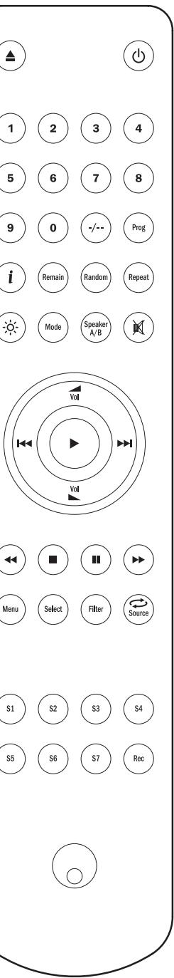
Select
Press to toggle through the five 851C input options. Refer to 'Operating instructions' section of the 851C manual for more information.
Program, Remain, Repeat, Random
Refer to Operating instructions' section of the 851C manual for more information.
Filter
Press to toggle through the three 851C digital filter options.
① Information
Press to display any additional 851C input signal information available.
Apple device compatibility
The Azur 851A/C Navigator remote control can control the basic functions of Apple devices such as Apple TV and Apple's iPod/iPhone/iPad range when docked in a Cambridge Audio or Apple dock.
Press and hold the source button that corresponds to the input that the Apple product is connected to whilst also pressing one of the buttons below.
The functions are slightly different depending on the Apple product.
Select
Play/pause
Stop or Menu
Press briefly to skip or navigate left or right. Press and hold to scan forwards or backwards.
Vol Used to control volume and/or navigate menus.

Used to navigate menus.
In addition, the Azur remote can be paired with up to six specific Apple devices using any of the six source buttons. This can be useful if you have more than one Apple product.
For more information on pairing refer to your Apple device's instruction manual.
Pairing - To pair with an Apple device, press and hold the required source button along with the button for six seconds. Some devices like Apple TV have visual indication once pairing is achieved.
Un-pairing - To un-pair an Apple device, press and hold any of the source buttons along with the button for six seconds.
Connections
When designing our amplifiers we include features that allow you to connect your system in various ways. The inclusion of features such as Pre-Out and Speaker B connections mean that you can flexibly configure your system depending on your requirements.
Basic connections
The diagram below shows the basic connection of your amplifier to a CD player using Input 1 (Unbalanced) and a pair of loudspeakers.
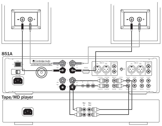
Tape/Recording connections
The diagram below shows how to connect the amplifier to a tape recorder or other source with a record and monitor connection.
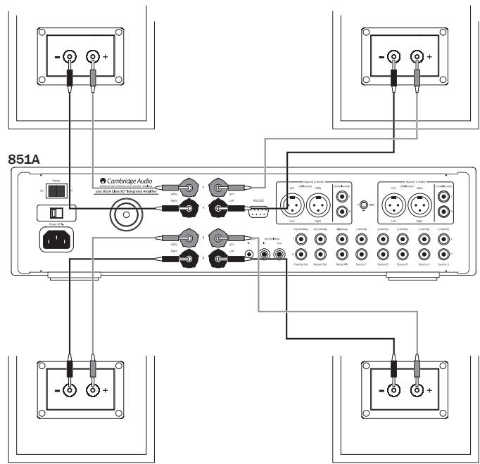
Speaker B connections
The Speaker B connections on the back of the amplifier allow for a second set of speakers to be used (i.e. speakers located in another room). The Speaker A/B button on the front panel allows this second set of speakers to be switched on and off.
Note: When using two pairs of speakers, use speakers with a minimum nominal impedance of 16 ohms.
Preamp Out connections
The Preamp Out sockets are for connecting to the input sockets of a power amplifier or active subwoofer. The diagram below shows how to connect the amplifier to an active subwoofer via the Line In inputs on the subwoofer.

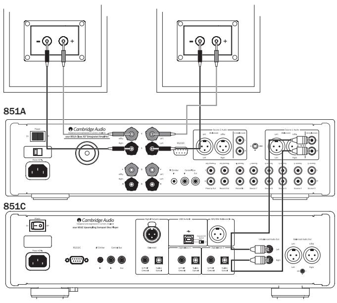
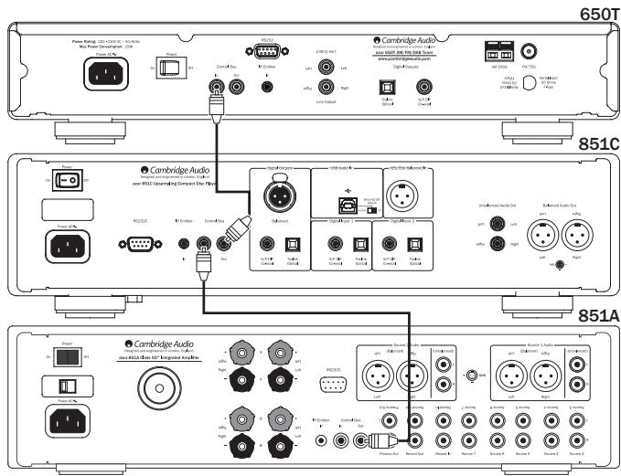
Balanced audio connections (Source 1 and 2)
The diagram below shows how to connect the 851A to the Azur 851C Upsampling CD player/DAC using the Balanced Audio inputs via three-pin XLR connectors. The 851A can also be connected to non-Cambridge Audio sources with balanced outputs.
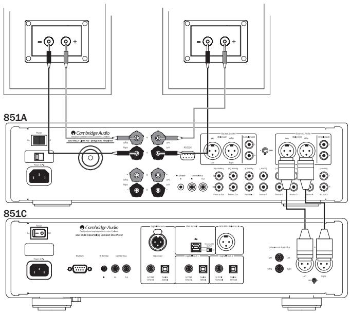
Balanced connections in an audio system are designed to reject electrical noise, from power wiring etc, and also the effects of noise currents flowing through ground connections. The basic principle of balanced interconnection is to get the signal you want by subtraction, using a three-wire connection. One signal wire (the hot or in-phase) carries the normal signal, while other (the cold or phase-inverted) carries an inverted version. The balanced input senses the difference between the two lines to give the wanted signal. Any noise voltages that appear identically on both lines (these are called common-mode signals) are cancelled by the subtraction. An additional advantage is that the connection effectively carries twice the signal level and so improves the signal-to-noise ratio.
The 851A and 851C are designed to work at their highest performance when a balanced interconnect is used.
Note: To select the balanced input on either Source 1 or 2, repeatedly pressing the Source 1 or Source 2 button on the front to toggle these inputs between 'Balanced' and 'Unbalanced' source input.
Operating instructions
Volume
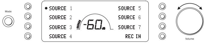
Adjust the volume control knob on the front panel (or using the remote control). The display will show the change in volume in decibels (dB). 'OdB' indicates maximum volume while lower volume settings progress into the negative range. This can also be changed to volume units (0-96) in the System Configure menu.
Speaker A/B
Press the Speaker A/B button to scroll through the speaker sets connected via the rear panel: speakers A, B or A and B.
Balance
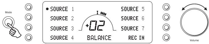
Press the Mode button to enter Balance mode. BALANCE will appear on the display and can be adjusted using the volume control. Press the Mode button again to return to Volume mode or wait 5 seconds for the 851A to automatically exit Balance mode.
Bass and Treble
These controls allow subtle adjustments to the tonal balance of the sound. Modify the sound through your loudspeakers and the Pre-Out sockets only; they do not affect the signals sent through the Tape Out connections. With a well produced CD and a good system the tone controls are unnecessary and can be bypassed by pressing the Direct button:
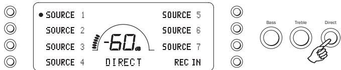
This completely removes them from the signal path for maximum fidelity. If the musical recording is of poor quality or other factors are affecting the sound quality, if desired you can adjust the tone controls to compensate. To use the tone controls press the Direct button so that the Bass/Treble icon (2) lights in the display indicating that they are active and direct mode is Off. Now press the Bass or Treble controls themselves to release them and allow adjustment; push them back in when finished:
The 851A stores whether direct mode is on or off for each input individually, for example it is possible to have the tone controls automatically active for the Tuner source but not the CD source.
Amplifier setup
The 851A features many advanced settings that allow it's use to be customised to user preference. The inputs can be named to reflect the actual source units you have, each input can be trimmed so that each sounds the same in terms of loudness when you switch between them and other options.
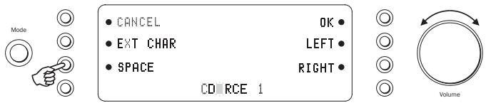
Press and hold the relevant input select button for four seconds to change its name. For example, if Input 1 is a CD player, name it "CD" etc. Letters are selected by turning the volume control to scroll through the available characters. Press LEFT or RIGHT to select which character you wish to edit. Press EXT CHAR to access an extended character set. Press OK to confirm and exit the input name change menu.
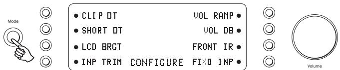
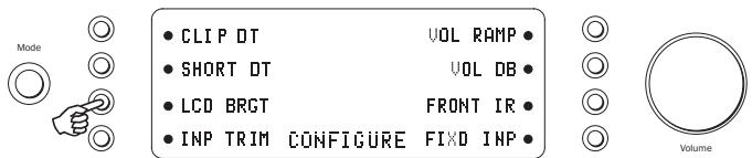
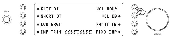
Press and hold the Mode button to access the System Configure menu. The menu options are Clip detector, LCD brightness, Speaker short detector, Input gain trim, Volume ramp, Volume display, Front IR and Fixed input gain.
To exit the System Configure menu and its sub-menus, press the Mode button again.
Clip detector / Speaker short detector
Refer to the 'CAP5' section of this manual for more information on the Clip and Short detection features of the 851A, as both can be enabled (default) or disabled.
LCD brightness
In the System Configure menu press the LCD input select button to scroll through bright/dim/off settings for the front panel display. Press the Mode button to exit.
Volume ramp
The 851A automatically ramps the volume down when going into Standby mode and up when coming out of Standby mode. To turn this feature off, press the VOL RAMP input select button in the System Configure menu and set to off. Press the Mode button to exit.
Volume display
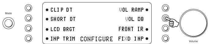
To change the volume display from decibels (-95 to 0dB) to arbitrary volume units (0 to 96 units) select VOL DB in the System Configure menu. Press the input select button to turn off the volume in decibels. Press the Mode button to exit.
Front IR
Used in conjunction with Custom Installation (C.I.) systems or IR repeater systems, it may be desirable to disable the front panel IR by setting FRONT IR to off (press the input select button to turn off). Press the Mode button to exit.
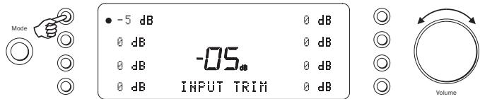
The relative levels of the inputs can be adjusted by gain trim. This allows each to be adjusted so that each sounds the same in terms of average loudness when you switch between them. Pick the loudest sounding source and trim its level until it matches the average perceived level of the others. Repeat this process if other sources also stand out as louder than the average.
To set the input gain trim for each source, select INP TRIM in the System Configure menu. Select the input required and use the volume control to set the gain between 0 and -12 dB (the available range is restricted if the volume is set very low). Press the Mode button to exit.
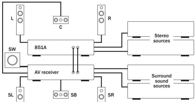
Any input of the 851A is able to be set for fixed gain. Whenever this input is selected the gain will automatically go to this value and will not be adjustable by the volume control. This feature allows the 851A to be effectively used as a stereo power amplifier (for that selected input only). For example, as well as operating as a pure stereo amplifier, the 851A can provide the amplification for the front left and right channels of a surround sound setup with an AV receiver providing amplification for the other channels and controlling the overall system volume.
When listening in stereo use the 851A and connected stereo sources as normal for best possible sound quality. For surround sound, select the fixed level input you have chosen on the 851A and now use the AV receiver to control the volume, select connected surround sound sources etc. You may wish to re-name the fixed level input as "A/V mode" or similar on the 851A. Make connections as below, the left and right preamp outputs of the AV receiver connect to the fixed gain input chosen on the 851A. As the gain can be fixed to any value it is easy to match the level of the 851A to that of the other AV channels.
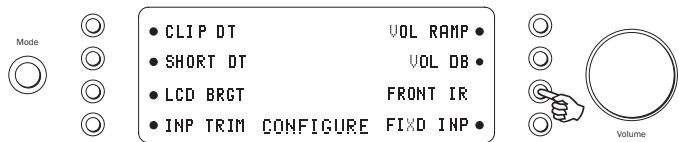
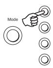
To set a fixed volume for a source, select FIXED INP in the System Configure menu:
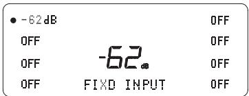
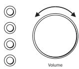
Select the input required and set the fixed gain using the volume control (the OFF setting does not disable the input but leaves the input gain subject to the volume control which is the default setting). When a source has a fixed input, the balance is always set to neutral. Press the Mode button to exit.
When going in/out of Standby mode the 851A can automatically turn on and off other connected Cambridge Audio Azur models that have control bus sockets. For this feature to work the units must be connected together (see diagram) by RCA/phono leads. The sockets are colourcoded orange on the rear panels of compatible Azur models. Loop out from the 851A Control Bus Out to the Control Bus In on another Azur model (e.g. 851C). Continue the chain to other Azur models if required.
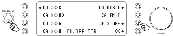
Now while the 851A is on press and hold the Standby/On button until ON/OFF CTR appears on the display:
Select the connected Azur models by pressing the appropriate input select button. For example, CA XXXC for an Azur CD player (851C), CA XXXBD for an Azur Blu-ray player, CA DAB T for an Azur DAB tuner etc.
Press ON & OFF to scroll through the options of ON (turns all Azur units on only), OFF (turns all Azur units into Standby only) or ON & OFF (turns all Azur units on and into Standby mode).
Press OK to confirm and exit.
CAP5 - Fiveway protection system
Cambridge Audio has developed a proprietary protection system to ensure reliability and a long life for its amplifiers and the speakers they are connected to. Note: Due to the required sensitivity of the CAP5 system, it is possible that mains power disturbances can falsely trigger CAP5 in extreme situations. This protection system comprises of five main protection methods:
1. DC detection
Indication - Unit has switched off during operation, display flashes "DC ERROR". Press the INFO input select button for a brief on-screen description and remedy, or read below for more information.
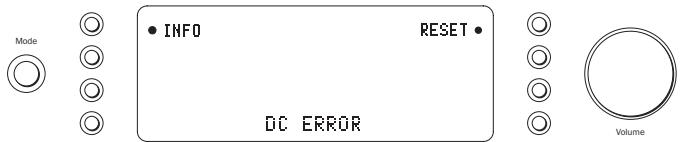
Description - CAP5 offers loudspeaker protection if the output of the amplifier goes to a high constant voltage (DC) because of some internal fault. This is a rare fault although detecting it could just save those expensive loudspeakers.
Remedy - Due to the necessary sensitivity of the DC protection circuit, extremely hard clipping of the amplifier may cause DC protection to be triggered. If this fault occurs press the RESET input select button, then press the Standby/On button to power up again and check operation with a reduced volume level. If the DC fault occurs again please contact your dealer for service.
2. Over temperature detection
Indication - Unit has switched off during operation, display flashes "OVER TEMP". Press the INFO input select button for a brief on-screen description and remedy, or read below for more information.
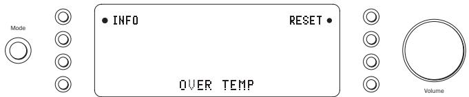
Description - Over temperature is caused by a combination of high listening levels and low impedance speakers. CAP5 includes temperature detection which constantly monitors the heat generated by the output transistors. If the monitored temperature reaches a high level (suitably within the limits of the output devices) the amplifier will automatically switch into a fault mode. The unit should ideally be left for 15 minutes in this state to cool down adequately. If the unit has not fully cooled down then the temperature may reach the limit soon after the amplifier is powered up. If the loudspeaker impedance is low the temperature of the amplifier may rise faster as the amplifier is working harder. If the amplifier is mounted in a cabinet or the ventilation slots are obstructed the over temperature detection may activate/reactivate after a short listening time.
Remedy - User related fault. The internal temperature of the output transistors has reached the over temperature limit. Press the RESET input select button and leave the unit for 15 minutes to cool down before pressing the Standby button to resume normal operation.
3. Overvoltage/overcurrent detection
Description - CAP5 offers V/I (voltage/current) protection by constantly monitoring the output transistors to keep them working inside their Safe Operating Area (SOA). The SOA is a set of limits given by the output transistor manufacturer to ensure reliability. The V/I protection has been incorporated within the amplifier circuitry to provide a fast response to temporary overload conditions. When the V/I protection is triggered the unit will continue to operate but distortion may be heard as the unit protects the output transistors.
Remedy - Reduce the volume. If distortion is still present, check the speaker connections and ratings.
4. Short circuit detection
Indication - Unit has not come out of Standby, display flashes "SPKR SHORT". Press the INFO input select button for a brief on-screen description and remedy, or read below for more information.
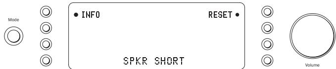
Description - During power up from Standby CAP5 performs a check on the loudspeaker terminals to see if a short across the terminals has been accidentally introduced (display flashes "SPKR CHECK"). If the resistance measured across the loudspeaker terminals is too low the unit will stay in Standby mode until the fault has been removed and Power up is re-attempted (display flashes "SPKR SHORT").
Remedy - User related fault. There may be a short circuit between the loudspeaker terminals. Press the RESET input select button and check all loudspeaker connections before attempting to switch the unit out of Standby (display will flash "SPKR CHECK" then "SPKR OK" when short circuit fixed).
It is possible to disable the short circuit detection feature by pressing the SHORT DT button to off when in the 851A System Configure menu, but it is not recommended. This would only be required if the loudspeakers have very low DC resistance.
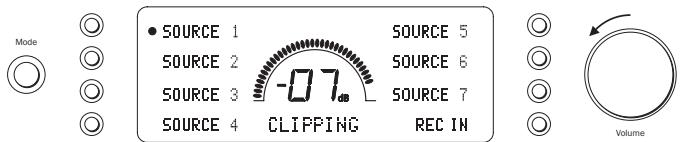
5. Intelligent clipping detection
Indication - Volume is reduced automatically, "CLIPPING" appears on the front panel display.
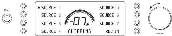
Description - CAP5 has the ability to detect when the amplifier starts to clip or overdrive at its output, which can damage loudspeakers, and degrade the sound. Clipping distortion is caused at high volume levels when the output signal attempts to go outside the maximum voltage that the amplifier can provide, causing the tops of the signal to flatten off. When CAP5 detects clipping the volume will be automatically reduced down until CAP5 detects an undistorted output.
It is possible to disable the clipping detection feature by pressing the CLIP DT button to off when in the 851A System Configure menu.
Note: Disabling the clipping detection is not advised as this feature has been added deliberately to protect the amplifier and loudspeakers.
Custom installation (C.I.) use
The 851A features a Control Bus input/output that allows un-modulated remote control commands (positive logic, TTL level) to be received electrically by the unit and looped to another unit if desired. These control commands are typically generated by custom installation (multi-room) systems or remote IR receiver systems. The Control Bus sockets are colour-coded orange.
An IR Emitter Input is also provided that allows modulated IR remote control commands to be received electrically by the unit. Commands on this input operate the unit only and are not looped out demodulated on the Control Bus Output.
An RS232C port is also featured which allows the 851A to be controlled by C.I. systems.
In addition the units feature 'direct' IR/Control codes as well as toggle codes for some of their features to simplify programming custom installation systems. Special direct On/Off and Mute commands can be accessed on the supplied remote control for teaching into C.I. systems as follows:
- Press and hold the Standby/On button. The remote first generates it's standby (toggle) command. Keep the button held down, after 12 seconds an amplifier "On" command will be generated. If the button is kept held down for a further 12 seconds, an amplifier player "Off" command is generated.
- Press and hold the Mute button. The remote first generates it's mute (toggle) command. Keep the button held down, after 12 seconds a "Mute on" command will be generated. If the button is kept held down for a further 12 seconds, a "Mute off" command is generated.
A full code table and RS232 protocol for this product is available on the Cambridge Audio website: www.cambridge-audio.com
Technical specifications
Power Output 120W RMS into 8 Ohms
THD (unweighted) < 0.001% 1 kHz
at 80% of rated power
< 0.01% 20 Hz - 20 kHz
at 80% of rated power
Frequency Response 10 Hz - 50 kHz +/- 1 dB
S/N ratio (ref 1W/8 Ohm) >93 dB
Input impedances Input 1 and 2 (balanced) 20 kOhm
Inputs 1-7 unbalanced 20 kOhm
Rec Input 20 kOhm
Power Amp damping factor >110 at 1 kHz
Max power consumption 800W
Minimum power Active (no signal) 70W
consumption Standby < 0.5W
Bass & Treble controls Shelving type
Max bass boost/cut +/- 10 dB at 10 Hz
Max treble boost/cut +/- 7.5 dB at 20 kHz
Dimensions (H x W x D) 115 x 430 x 385mm
(4.5 x 16.9 x 15.2")
Weight 15.0kg (33Lbs)
Troubleshooting
There is no power
Ensure the AC power cord is connected securely.
Ensure the plug is fully inserted into the wall socket and is switched on.
Check fuse in the mains plug or adaptor.
There is no sound
Make sure the unit is not in Standby mode.
Check that source component is properly connected.
Check that REC IN is not switched on (unless record input is required).
Check that your speakers are properly connected.
If using Speaker B terminals check they are switched on.
Make sure unit is not in mute mode.
There is no sound on one channel
Ensure that balance control is in the correct position.
Check speaker connections.
Check interconnects.
There is a loud buzz or hum
Check turntable or tone arm for ground and connection lead fault.
Ensure no interconnects are loose or defective.
Ensure that your tape deck/turntable is not too close to the amplifier.
Unable to make or play tape recordings
Check that Record In and Record Out have been connected correctly.
There is weak bass or diffused stereo imaging
Ensure that speakers are not wired out of phase.
Message on display flashing
See section on CAP5 protection system.
The remote handset will not function
Check that the batteries have not expired.
Ensure that nothing is blocking the remote sensor.
For more frequently asked questions (FAQ's), technical advice and information on getting the most out of your 851A, please visit the Support section on Cambridge Audio's website:
www.cambridgeaudio.com/support.php
For all servicing, in or out of warranty, please contact your dealer.
www.cambridge-audio.com