
TRANSCHORUS 210 - Guitar amplifier PEAVEY - Free user manual and instructions
Find the device manual for free TRANSCHORUS 210 PEAVEY in PDF.
| Product Type | Guitar Amplifier |
| Brand | PEAVEY |
| Model | TRANSCHORUS 210 |
| Emulation Technology | TransTube® (tube emulation) |
| Channels | 3 separate channels: Clean, Crunch, Lead |
| Built-in Effects | Stereo Chorus (adjustable speed and depth), Reverb |
| Equalization | Passive Low, Mid, High for Clean; Low, Mid, High for Crunch and Lead |
| Inputs | Hi Gain (+6 dB boost), Lo Gain (for high output instruments) |
| Outputs | Stereo Preamp Out, Stereo Power Amp In, Stereo Headphone Jack |
| Power Control | T. Dynamics® (adjustable from 10% to 100% power) |
| Speakers | 2 x 10" |
| Included Footswitch | Footswitch for channel selection and chorus on/off |
| Power Supply | IEC connector, voltage per local specifications |
| Safety | Mandatory grounding; do not expose to water or moisture |
| Cleaning | Dry cloth only |
| Repairs | Refer to qualified personnel – no user-serviceable parts |
| Rack Mountable | Yes, with proper rear support |
Frequently Asked Questions - TRANSCHORUS 210 PEAVEY
User questions about TRANSCHORUS 210 PEAVEY
0 question about this device. Answer the ones you know or ask your own.
Ask a new question about this device
Download the instructions for your Guitar amplifier in PDF format for free! Find your manual TRANSCHORUS 210 - PEAVEY and take your electronic device back in hand. On this page are published all the documents necessary for the use of your device. TRANSCHORUS 210 by PEAVEY.
USER MANUAL TRANSCHORUS 210 PEAVEY
Intended to alert the user to the presence of uninsulated "dangerous voltage" within the product's enclosure that may be of sufficient magnitude to constitute a risk of electric shock to persons.

Intended to alert the user of the presence of important operating and maintenance (servicing) instructions in the literature accompanying the product.
CAUTION: Risk of electrical shock — DO NOT OPEN!
CAUTION: To reduce the risk of electric shock, do not remove cover. No user serviceable parts inside. Refer servicing to qualified service personnel.
WARNING: To prevent electrical shock or fire hazard, do not expose this appliance to rain or moisture. Before using this appliance, read the operating guide for further warnings.

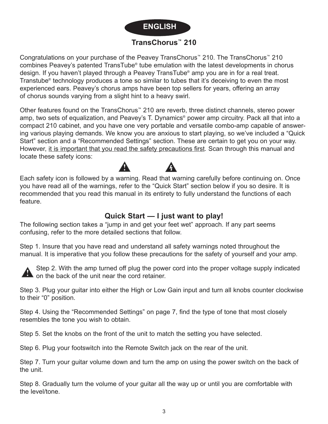
Congratulations on your purchase of the Peavey TransChorus™ 210. The TransChorus™ 210 combines Peavey's patented TransTube® tube emulation with the latest developments in chorus design. If you haven't played through a Peavey TransTube® amp you are in for a real treat. Transtube® technology produces a tone so similar to tubes that it's deceiving to even the most experienced ears. Peavey's chorus amps have been top sellers for years, offering an array of chorus sounds varying from a slight hint to a heavy swirl.
Other features found on the TransChorus™ 210 are reverb, three distinct channels, stereo power amp, two sets of equalization, and Peavey's T. Dynamics® power amp circuitry. Pack all that into a compact 210 cabinet, and you have one very portable and versatile combo-amp capable of answering various playing demands. We know you are anxious to start playing, so we've included a "Quick Start" section and a "Recommended Settings" section. These are certain to get you on your way. However, it is important that you read the safety precautions first. Scan through this manual and locate these safety icons:


Each safety icon is followed by a warning. Read that warning carefully before continuing on. Once you have read all of the warnings, refer to the "Quick Start" section below if you so desire. It is recommended that you read this manual in its entirety to fully understand the functions of each feature.
Quick Start — I just want to play!
The following section takes a "jump in and get your feet wet" approach. If any part seems confusing, refer to the more detailed sections that follow.
Step 1. Insure that you have read and understand all safety warnings noted throughout the manual. It is imperative that you follow these precautions for the safety of yourself and your amp.

Step 2. With the amp turned off plug the power cord into the proper voltage supply indicated on the back of the unit near the cord retainer.
Step 3. Plug your guitar into either the High or Low Gain input and turn all knobs counter clockwise to their "0" position.
Step 4. Using the "Recommended Settings" on page 7, find the type of tone that most closely resembles the tone you wish to obtain.
Step 5. Set the knobs on the front of the unit to match the setting you have selected.
Step 6. Plug your footswitch into the Remote Switch jack on the rear of the unit.
Step 7. Turn your guitar volume down and turn the amp on using the power switch on the back of the unit.
Step 8. Gradually turn the volume of your guitar all the way up or until you are comfortable with the level/tone.
Step 9. Experiment with the footswitch to get familiar with how the three different channels are selected.
Note: The Select button on the amp must be pressed (down position) in order for the footswitch to work.
Step 10. To adjust the overall level of each channel, use the Volume knob for the Clean channel and the Post Gain controls for the Crunch and Lead channels.
Step 11. To adjust the amount of distortion in the Crunch and Lead channels, use the Pre Gain knob. Turning the knob clockwise results in increased distortion.
Step 12. You should be able to play at this time. Push the various buttons to hear their effect on your tone. Vary the Reverb or Chorus Rate and Depth knobs to get a feel for their effect as well. Most importantly....READ THE REST OF THIS MANUAL.
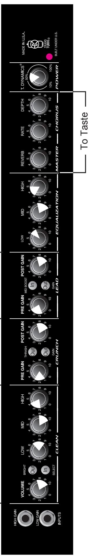
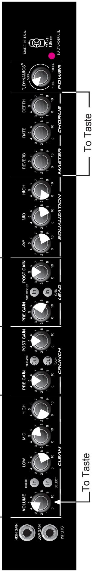
FRONT PANEL
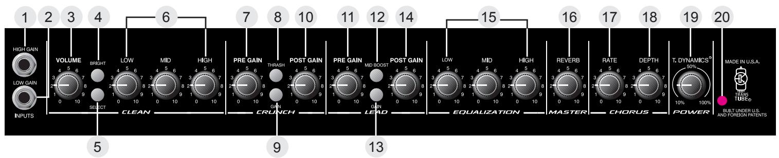
Hi Gain Input (1)
Used for most electric guitars. It is 6 dB louder than the Low Gain input.
Low Gain (2)
Provided for instruments that have extremely high outputs, which can result in overdriving (distorting) the High Gain input. If both inputs are used simultaneously, the output levels are the same (both are low gain).
Clean Channel
Volume (3)
Controls the output level of the Clean channel.
Bright Switch (4)
When activated (pressed in), this switch provides a 6 dB boost to the extreme high frequency portion of your signal.
Select Switch (5)
This switch selects between the Clean and Lead channels. The "in" position selects the Lead channel and the "out" position selects the Clean. Channel selection may also be achieved by using the remote footswitch. The Select Switch must be in the "in" position for the footswitch to operate. Use of the footswitch will also allow you to select between the Crunch and Lead channels.
Low, Mid, and High EQ (6)
This section is a passive tone control for the clean channel. Adjusting these knobs clockwise will pass more low, mid, or high frequency content of the Clean channel to the internal power amps.
Crunch Channel
Pregain (7)
Controls the input level of the Crunch channel. Adjusting this control clockwise will increase the input level, thus increasing distortion.
Thrash Switch (8)
When activated (in), this switch attenuates a preset portion of the mid range resulting in a more "heavy" sound and an apparent increase in distortion.
Gain Switch (9)
When activated (in), this switch boosts the pregain of the Crunch channel resulting in increased distortion. This effect is often used to get intentional feedback and increased sustain.
Post Gain (10)
Controls the output level of the Crunch channel. Adjusting this control clockwise will result in increased volume. The desired tone and distortion level should be obtained prior to adjusting this control for proper level. Consider this control the volume control for the Crunch channel.
Lead Channel
Pregain (11)
Controls the input level of the Lead channel. Adjusting this control clockwise will increase the input level, thus increasing distortion.
Mid Boost Switch (12)
When activated (in), this switch boosts the mid frequencies. This effect is often desired when miking an amp that is producing distorted guitar signals. Selecting the Mid Boost will bring the signal up in the overall mix during lead passages.
Gain Switch (13)
When activated (in), this switch boosts the pregain of the Lead channel resulting in increased distortion. This effect is often used to get intentional feedback and increased sustain.
Post Gain (14)
Controls the output level of the Lead channel. Adjusting this control clockwise will result in increased volume. The desired tone and distortion level should be obtained prior to adjusting this control for proper level. Consider this control the volume control for the Lead channel.
Low, Mid, and High EQ (15)
This section is a passive tone control for the Crunch and Lead channels. Adjusting these knobs clockwise will pass more low, mid, or high frequency content of these to the internal power amps .
Reverb (16)
Adjusting this control clockwise will result in more reverb content in the output of the amp regardless of the channel. The reverb can be defeated completely by rotating the control counter clockwise.
Rate (17)
Adjusting this control clockwise will result in an increase in the sweep rate (frequency) of the chorus effect. The chorus can only be disabled from the footswitch.
Depth (18)
Adjusting this control clockwise will result in an increase in the depth or intensity of the chorus effect. This control adjusts the amount of chorus you actually hear from the output of the amp.
T. Dynamics (19)
This control adjusts the usable power of the internal power amps from 10% (counter clockwise) to 100% (clockwise). Rotating this control clockwise will result in more available power. This effect is often set to lower levels in order for the power amp compression simulation to be more apparent, allowing you to overdrive the power amp at lower volume levels, achieving a tube power amp clipping/compression quality.
Power LED (20)
Illuminates when power is supplied to the amp. If this LED is lit, the amp is on.
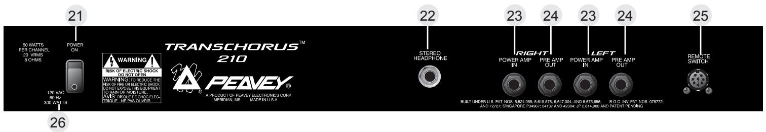
REAR PANEL
Power Switch (21)
Placing this switch in the "ON" position will result in power being supplied to the unit. The Power LED (20) will illuminate when the amp is on.
Stereo Headphone (22)
This 1/4" stereo output jack is designed to accommodate standard, stereo headphones. Plugging a set of headphones into this jack will disconnect the signal going to the power amplifiers of the unit, and no output can be heard from the unit's speakers. This feature provides an excellent practice tool.
Power Amp In (23)
These left and right mono 1/4" jacks provide an input to each of the power amplifiers. When used in conjunction with the Preamp Out jacks (24), a stereo effects loop is formed allowing the use of stereo delays and various effects.
Preamp Out (24)
These left and right mono 1/4" jacks provide an output from each of the preamps. When used in conjunction with the Power Amp In jacks (23), a stereo effects loop is formed allowing the use of stereo delays and various effects.
Remote Switch (25)
This jack is provided for the connection of the supplied footswitch. The footswitch is a multi-function type allowing you to select Clean, Crunch, or Lead and to defeat the Chorus effects. To use the footswitch ensure that the footswitch plug is inserted fully into the jack and that the Select switch is pressed in (down position) on the front panel.
AC LINE CORD—120 V PRODUCTS ONLY (26)
For you safety, we have incorporated a three-wire line (mains) cable with proper grounding facilities. It is not advisable to remove the ground pin under any circumstances. If it is necessary to use the equipment without proper grounding facilities, suitable grounding adapters should be used. Less noise and greatly reduced shock hazard exists when the unit is operated with the proper grounded receptacles.

NOTE: FOR UK ONLY
As the colors of the wires in the mains lead of this apparatus may not correspond with the colored markings identifying the terminals in your plug, proceed as follows:
- The wire which is colored green and yellow must be connected to the terminal which is marked by the letter E, or by the earth symbol, or colored green or green and yellow.
- The wire which is colored blue must be connected to the terminal which is marked with the letter N, or the color black.
- The wire which is colored brown must be connected to the terminal which is marked with the letter L, or the color red.
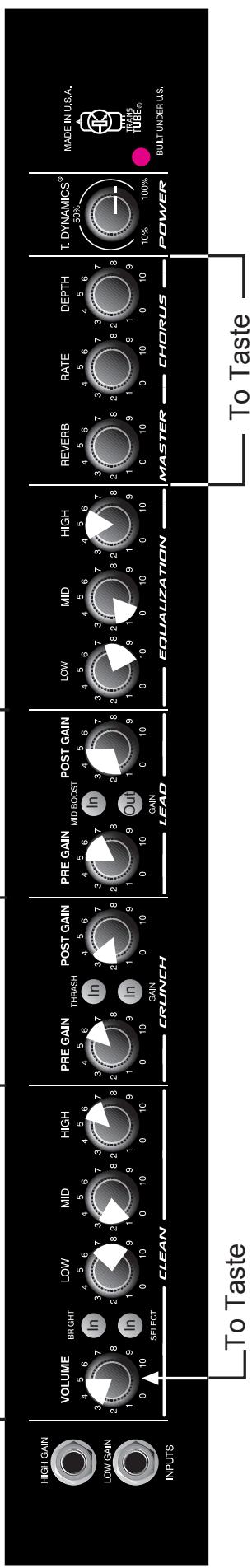
MODERATE CLEAN METAL DISTORTION


TRANSCHORUS™ 210 SPECIFICATIONS
(ALL MEASUREMENTS @ 120 V AC, 60HZ)
POWER AMPLIFIER SECTION
RATED OUTPUT POWER:
Power specs measured with T. Dynamics @ 100%
(5% THD, 1 kHz, 120 V AC)
50 W RMS per channel, into 8 ohms
FREQUENCY RESPONSE:
Stereo mode into 8 ohm, power amp inputs
-3 dB, +2 dB, 70 Hz to 20 kHz, @ 45 W RMS into
8 ohms
HUM AND NOISE:
Unweighted, 20Hz to 22kHz
Greater than 90 dB, both channels
POWER CONSUMPTION:
Domestic Model: 120 V AC, 60 Hz, 2.5A, 300 W
Export Model: 220 to 240 V AC, 50/60 Hz, 300 W
PREAMP SECTION
(The following specs are measured @ 1 kHz with the controls preset as follows:)
Push Bright, off (out)
Channel Select Clean (out)
Low and High @ 10
Mid @ 0
Crunch Pre and Post Gain @ 10
Gain and Thrash, off (out)
Lead Pre and Post Gain @ 10
Gain and Mid Boost, off (out)
Normal levels are with normal volume @ 5
Minimum levels are with clean volume @ 10
PREAMP HIGH GAIN INPUT:
Impedance: High-Z, 1 M ohm
Nominal Input Level: -12 dBV, 250 mV RMS
Minimum Input Level: -22 dBV, 79 mV RMS
Maximum Input level: 0 dBV, 1 V RMS
PREAMP LOW GAIN INPUT:
Impedance: High-Z, 44 k ohms
Nominal Input Level: -6 dBV, 500 mV RMS
Minimum Input Level: -16 dBV, 158 mV RMS
Maximum Input level: 6 dBV, 2 V RMS
PREAMP OUTPUT:
Load Impedance: 300 ohm or greater
Nominal Output Level: 0 dBV, 1 V RMS
POWER AMP INPUT:
Impedance: High-Z, 30 k ohms
Designed Input Level: 0 dBV, 1 V RMS
(Switching jack provides preamp output to power amp input connection when not used.)
SYSTEM HUM AND NOISE @ NOMINAL INPUT LEVEL
UNWEIGHTED, 20 Hz to 22 kHz
Greater than 75 dB, below rated power
EQUALIZATION:
Special low, mid and high passive type EQ
Push Bright: +4 dBV @ 2 kHz, (Clean channel)
Push Thrash: -6 dBV notch 1 kHz, (Crunch channel)
Push Mid boost: +3 dBV band pass 1 kHz, (Lead channel)
Push Gain: Increase gain both Lead and Crunch channels
EXTERNAL FOOT SWITCH FUNCTIONS:
Lead/Crunch: Selects lead or crunch channel.
Bypass/Clean: Lead and Crunch channel defeat
(channel switch "IN")
Select/Chorus: Defeat Chorus
DIMENSIONS AND WEIGHT (H x W x D):
18.5" x 23.375" x 11.375"
47cm x 10.60cm x 29cm
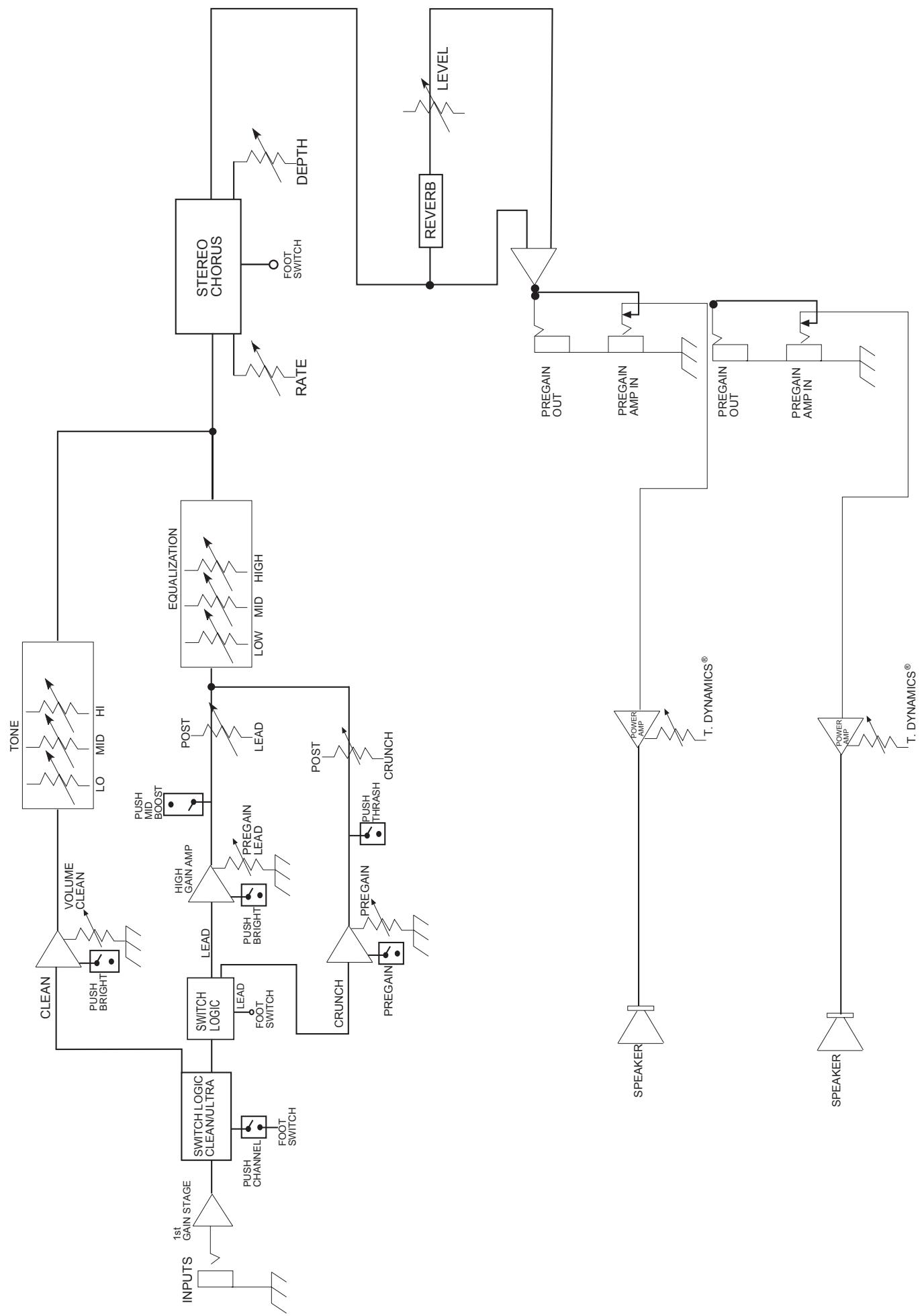
TransChorus™ 210 BLOCK DIAGRAM
IMPORTANT SAFETY INSTRUCTIONS
WARNING: When using electric products, basic cautions should always be followed, including the following:
- Read these instructions.
- Keep these instructions.
- Heed all warnings.
- Follow all instructions.
- Do not use this apparatus near water. For example, near or in a bathtub, swimming pool, sink, wet basement, etc.
- Clean only with a damp cloth.
- Do not block any of the ventilation openings. Install in accordance with manufacturer's instructions. It should not be placed flat against a wall or placed in a built-in enclosure that will impede the flow of cooling air.
- Do not install near any heat sources such as radiators, heat registers, stoves or other apparatus (including amplifiers) that produce heat.
- Do not defeat the safety purpose of the polarized or grounding-type plug. A polarized plug has two blades with one wider than the other. A grounding type plug has two blades and a third grounding plug. The wide blade or third prong is provided for your safety. When the provided plug does not fit into your inlet, consult an electrician for replacement of the obsolete outlet. Never break off the grounding. Write for our free booklet "Shock Hazard and Grounding". Connect only to a power supply of the type marked on the unit adjacent to the power supply cord.
- Protect the power cord from being walked on or pinched, particularly at plugs, convenience receptacles, and the point they exit from the apparatus.
- Only use attachments/accessories provided by the manufacturer.
- Use only with a cart, stand, tripod, bracket, or table specified by the manufacturer, or sold with the apparatus. When a cart is used, use caution when moving the cart/apparatus combination to avoid injury from tip-over.
- Unplug this apparatus during lightning storms or when unused for long periods of time.
- Refer all servicing to qualified service personnel. Servicing is required when the apparatus has been damaged in any way, such as power-supply cord or plug is damaged, liquid has been spilled or objects have fallen into the apparatus, the apparatus has been exposed to rain or moisture, does not operate normally, or has been dropped.
- If this product is to be mounted in an equipment rack, rear support should be provided.
- Exposure to extremely high noise levels may cause a permanent hearing loss. Individuals vary considerably in susceptibility to noise-induced hearing loss, but nearly everyone will lose some hearing if exposed to sufficiently intense noise for a sufficient time. The U.S. Government's Occupational and Health Administration (OSHA) has specified the following permissible noise level exposures:
| Duration Per Day In Hours | Sound Level dBA, Slow Response |
| 8 | 90 |
| 6 | 92 |
| 4 | 95 |
| 3 | 97 |
| 2 | 100 |
| 1 1/2 | 102 |
| 1 | 105 |
| 1/2 | 110 |
| 1/4 or less | 115 |
According to OSHA, any exposure in excess of the above permissible limits could result in some hearing loss. Ear plugs or protectors to the ear canals or over the ears must be worn when operating this amplification system in order to prevent a permanent hearing loss, if exposure is in excess of the limits as set forth above. To ensure against potentially dangerous exposure to high sound pressure levels, it is recommended that all persons exposed to equipment capable of producing high sound pressure levels such as this amplification system be protected by hearing protectors while this unit is in operation.
SAVE THESE INSTRUCTIONS!
ESPANOL TransChorusTM 210
(5% THD, 1 kHz, 120 V CA)
Power specs measured with T. Dynamics @ 100%
(5% THD, 1 kHz, 120 V AC)
50 W RMS per channel, into 8 ohms
FREQUENCY RESPONSE:
Stereo mode into 8 ohm, power amp inputs
-3 dB, +2 dB, 70 Hz to 20 kHz, @ 45 W RMS into
8 ohms
HUM AND NOISE:
Unweighted, 20Hz to 22kHz
Greater than 90 dB, both channels
POWER CONSUMPTION:
Domestic Model: 120 V AC, 60 Hz, 2.5A, 300 W
Export Model: 220 to 240 V AC, 50/60 Hz, 300 W
PREAMP SECTION
(The following specs are measured @ 1 kHz with the controls preset as follows:)
Push Bright, off (out)
Channel Select Clean (out)
Low and High @ 10
Mid @ 0
Crunch Pre and Post Gain @ 10
Gain and Thrash, off (out)
Lead Pre and Post Gain @ 10
Gain and Mid Boost, off (out)
Normal levels are with normal volume @ 5
Minimum levels are with clean volume @ 10
PREAMP HIGH GAIN INPUT:
Impedance: High-Z, 1 M ohm
Nominal Input Level: -12 dBV, 250 mV RMS
Minimum Input Level: -22 dBV, 79 mV RMS
Maximum Input level: 0 dBV, 1 V RMS
PREAMP LOW GAIN INPUT:
Impedance: High-Z, 44 k ohms
Nominal Input Level: -6 dBV, 500 mV RMS
Minimum Input Level: -16 dBV, 158 mV RMS
Maximum Input level: 6 dBV, 2 V RMS
PREAMP OUTPUT:
Load Impedance: 300 ohm or greater
Nominal Output Level: 0 dBV, 1 V RMS
POWER AMP INPUT:
Impedance: High-Z, 30 k ohms
Designed Input Level: 0 dBV, 1 V RMS
(Switching jack provides preamp output to power amp input connection when not used.)
SYSTEM HUM AND NOISE @ NOMINAL INPUT LEVEL
UNWEIGHTED, 20 Hz to 22 kHz
Greater than 75 dB, below rated power
EQUALIZATION:
Special low, mid and high passive type EQ
Push Bright: +4 dBV @ 2 kHz, (Clean channel)
Push Thrash: -6 dBV notch 1 kHz, (Crunch channel)
Push Mid boost: +3 dBV band pass 1 kHz, (Lead channel)
Push Gain: Increase gain both Lead and Crunch channels
EXTERNAL FOOT SWITCH FUNCTIONS:
Lead/Crunch: Selects lead or crunch channel.
Bypass/Clean: Lead and Crunch channel defeat
(channel switch "IN")
Select/Chorus: Defeat Chorus
DIMENSIONS AND WEIGHT (H x W x D):
18.5" x 23.375" x 11.375"
47cm x 10.60cm x 29cm
NOTE IMPORTANTE CONCERNANT LA SECURITE
CONSERVEZ CES INSTRUCTIONS!
DEUTSCH
TransChorus™ 210
Low, Mid, and High EQ (6)
Low, Mid, and High EQ (15)
Stereo Headphone (22)
Power specs measured with T. Dynamics @ 100%
(5% THD, 1 kHz, 120 V AC)
50 W RMS per channel, into 8 ohms
FREQUENCY RESPONSE:
Stereo mode into 8 ohm, power amp inputs
-3 dB, +2 dB, 70 Hz to 20 kHz, @ 45 W RMS into
8 ohms
HUM AND NOISE:
Unweighted, 20Hz to 22kHz
Greater than 90 dB, both channels
POWER CONSUMPTION:
Domestic Model: 120 V AC, 60 Hz, 2.5A, 300 W
Export Model: 220 to 240 V AC, 50/60 Hz, 300 W
PREAMP SECTION
(The following specs are measured @ 1 kHz with the controls preset as follows:)
Push Bright, off (out)
Channel Select Clean (out)
Low and High @ 10
Mid @ 0
Crunch Pre and Post Gain @ 10
Gain and Thrash, off (out)
Lead Pre and Post Gain @ 10
Gain and Mid Boost, off (out)
Normal levels are with normal volume @ 5
Minimum levels are with clean volume @ 10
PREAMP HIGH GAIN INPUT:
Impedance: High-Z, 1 M ohm
Nominal Input Level: -12 dBV, 250 mV RMS
Minimum Input Level: -22 dBV, 79 mV RMS
Maximum Input level: 0 dBV, 1 V RMS
PREAMP LOW GAIN INPUT:
Impedance: High-Z, 44 k ohms
Nominal Input Level: -6 dBV, 500 mV RMS
Minimum Input Level: -16 dBV, 158 mV RMS
Maximum Input level: 6 dBV, 2 V RMS
PREAMP OUTPUT:
Load Impedance: 300 ohm or greater
Nominal Output Level: 0 dBV, 1 V RMS
POWER AMP INPUT:
Impedance: High-Z, 30 k ohms
Designed Input Level: 0 dBV, 1 V RMS
(Switching jack provides preamp output to power amp input connection when not used.)
SYSTEM HUM AND NOISE @ NOMINAL INPUT LEVEL
UNWEIGHTED, 20 Hz to 22 kHz
Greater than 75 dB, below rated power
EQUALIZATION:
Special low, mid and high passive type EQ
Push Bright: +4 dBV @ 2 kHz, (Clean channel)
Push Thrash: -6 dBV notch 1 kHz, (Crunch channel)
Push Mid boost: +3 dBV band pass 1 kHz, (Lead channel)
Push Gain: Increase gain both Lead and Crunch channels
EXTERNAL FOOT SWITCH FUNCTIONS:
Lead/Crunch: Selects lead or crunch channel.
Bypass/Clean: Lead and Crunch channel defeat
(channel switch "IN")
Select/Chorus: Defeat Chorus
DIMENSIONS AND WEIGHT (H x W x D):
18.5" x 23.375" x 11.375"
47cm x 10.60cm x 29cm
Effective Date: July 1, 1998
What This Warranty Covers
Your Peavey Warranty covers defects in material and workmanship in Peavey products purchased and serviced in the U.S.A. and Canada.
What This Warranty Does Not Cover
The Warranty does not cover: (1) damage caused by accident, misuse, abuse, improper installation or operation, rental, product modification or neglect; (2) damage occurring during shipment; (3) damage caused by repair or service performed by persons not authorized by Peavey; (4) products on which the serial number has been altered, defaced or removed; (5) products not purchased from an Authorized Peavey Dealer.
Who This Warranty Protects
This Warranty protects only the original retail purchaser of the product.
How Long This Warranty Lasts
The Warranty begins on the date of purchase by the original retail purchaser. The duration of the Warranty is as follows:
| Product Category | Duration |
| Guitars/Basses, Amplifiers, Pre-Amplifiers, Mixers, Electronic Crossovers and Equalizers | 2 years * (+ 3 years) |
| Drums | 2 years * (+ 1 year) |
| Enclosures | 3 years * (+ 2 years) |
| Digital Effect Devices and Keyboard and MIDI Controllers | 1 year * (+ 1 year) |
| Microphones | 2 years |
| Speaker Components (incl. speakers, baskets, drivers, diaphragm replacement kits and passive crossovers) and all Accessories | 1 year |
| Tubes and Meters | 90 days |
[denotes additional warranty period applicable if optional Warranty Registration Card is completed and returned to Peavey by original retail purchaser within 90 days of purchase.]
What Peavey Will Do
We will repair or replace (at Peavey's discretion) products covered by warranty at no charge for labor or materials. If the product or component must be shipped to Peavey for warranty service, the consumer must pay initial shipping charges. If the repairs are covered by warranty, Peavey will pay the return shipping charges.
How To Get Warranty Service
(1) Take the defective item and your sales receipt or other proof of date of purchase to your Authorized Peavey Dealer or Authorized Peavey Service Center.
OR
(2) Ship the defective item, prepaid, to Peavey Electronics Corporation, International Service Center, 412 Highway 11 & 80 East, Meridian, MS 39301 or Peavey Canada Ltd., 95 Shields Court, Markham, Ontario, Canada L3R 9T5. Include a detailed description of the problem, together with a copy of your sales receipt or other proof of date of purchase as evidence of warranty coverage. Also provide a complete return address.
Limitation of Implied Warranties
ANY IMPLIED WARRANTYES, INCLUDING WARRANTYES OF MERCHANTABILITY AND FITNESS FOR A PARTICULAR PURPOSE, ARE LIMITED IN DURATION TO THE LENGTH OF THIS WARRANTY.
Some states do not allow limitations on how long an implied warranty lasts, so the above limitation may not apply to you.
Exclusions of Damages
PEAVEY'S LIABILITY FOR ANY DEFECTIVE PRODUCT IS LIMITED TO THE REPAIR OR REPLACEMENT OF THE PRODUCT, AT PEAVEY'S OPTION. IF WE ELECT TO REPLACE THE PRODUCT, THE REPLACEMENT MAY BE A RECONDITIONED UNIT. PEAVEY SHALL NOT BE LIABLE FOR DAMAGES BASED ON INCONVENIENCE, LOSS OF USE, LOST PROFITS, LOST SAVINGS, DAMAGE TO ANY OTHER EQUIPMENT OR OTHER ITEMS AT THE SITE OF USE, OR ANY OTHER DAMAGES WHETHER INCIDENTAL, CONSEQUENTIAL OR OTHERWISE, EVEN IF PEAVEY HAS BEEN ADVISED OF THE POSSIBILITY OF SUCH DAMAGES
Some states do not allow the exclusion or limitation of incidental or consequential damages, so the above limitation or exclusion may not apply to you.
This Warranty gives you specific legal rights, and you may also have other rights which vary from state to state.
If you have any questions about this warranty or service received or if you need assistance in locating an Authorized Service Center, please contact the Peavey International Service Center at (601) 483-5365 / Peavey Canada Ltd. at (905) 475-2578.
Features and specifications subject to change without notice.

PEAVEX
Features and specifications subject to change without notice.
Peavey Electronics Corporation • 711 A Street • Meridian, MS 39301 • U.S.A.
(601) 483-5367 • Fax (601) 486-1678 • www.peavey.com