
TRANSFORMER 212 - Guitar amplifier PEAVEY - Free user manual and instructions
Find the device manual for free TRANSFORMER 212 PEAVEY in PDF.

| Product Type | Modeling guitar combo amplifier |
| Brand | Peavey |
| Model | Transformer 212 |
| Number of Speakers | 2 x 12" (estimated) |
| Output Power | Approximately 100 W RMS (estimated) |
| Power Supply | Mains 100-240 V, 50/60 Hz |
| Amp Modeling | 12 distinct models (Clean, Crunch, High Gain, etc.) |
| Built-in Effects | Reverb/Delay, 5 modulations (Chorus, Flanger, Phaser, Tremolo, Rotary) |
| Presets | 32 (16 factory + 16 user) |
| Built-in Tuner | Yes, guitar and chromatic modes |
| Effects Loop | Yes (Send/Return 1/4" jack) |
| Footswitch Included | Yes, PFC 4 (8-pin DIN) |
| Instrument Inputs | 2 (High Gain and Low Gain) |
| Headphone Output | Yes (1/4" stereo jack) |
| MIDI | In (8-pin) and Out (5-pin) |
| Equalization | 3-band (Bass, Mid, Treble) with simulation according to modeled amp |
| TransTube Technology | Yes, with T. Dynamics control |
| Dimensions (approx.) | 50 x 45 x 30 cm (estimated) |
| Weight (approx.) | 20 kg (estimated) |
| Maintenance and Cleaning | Clean with a soft dry cloth. Do not use chemical products. |
| Safety | Do not expose to rain or moisture. Disconnect before maintenance. Have repairs done by an authorized technician. |
| Spare Parts and Repairability | Contact Peavey customer service or an authorized dealer. |
Frequently Asked Questions - TRANSFORMER 212 PEAVEY
User questions about TRANSFORMER 212 PEAVEY
0 question about this device. Answer the ones you know or ask your own.
Ask a new question about this device
Download the instructions for your Guitar amplifier in PDF format for free! Find your manual TRANSFORMER 212 - PEAVEY and take your electronic device back in hand. On this page are published all the documents necessary for the use of your device. TRANSFORMER 212 by PEAVEY.
USER MANUAL TRANSFORMER 212 PEAVEY
Intended to alert the user to the presence of uninsulated "dangerous voltage" within the product's enclosure that may be of sufficient magnitude to constitute a risk of electric shock to persons.

Intended to alert the user of the presence of important operating and maintenance (servicing) instructions in the literature accompanying the product.
CAUTION: Risk of electrical shock — DO NOT OPEN!
CAUTION: To reduce the risk of electric shock, do not remove cover. No user serviceable parts inside. Refer servicing to qualified service personnel.
WARNING: To prevent electrical shock or fire hazard, do not expose this appliance to rain or moisture. Before using this appliance, read the operating guide for further warnings.

Congratulations on your purchase of the world's most technologically advanced guitar amp, the Transformer™ by Peavey. Though instrument amplifier emulation has been occurring for some time now, none have accomplished what Peavey has in the Transformer. Within a small, light weight combo package, Peavey has managed to emulate both the voicing and dampening characteristics of some of the world's most popular amplifiers using TransTube® Technology.
This guide covers both the Transformer 112 and the Transformer 212. The difference in the two models are noted where applicable. It is important that you read this guide in its entirety. There are extra functions within the Transformer that are not made apparent by the front panel labeling. Just like a computer may have "hot key" combinations (pressing two keys will perform a distinct function), the Transformer uses certain button and knob combinations to achieve special functions. These are explained in detail within this guide. A chart indicating these "hot key" combinations is included for quick reference and a complete section, Transformer Tricks, has been dedicated to the subject.
The Features list and Quick Start section will familiarize you with the Transformer. We're confident that you will be amazed at the great sound of this amp; however, please read the manual in its entirety. Doing so will give you the knowledge you need to mold and shape your tone and create voicings reminiscent of classic amp designs as well as modern icons. Let's get started!
FEATURES
- Simple interface for ease of standard operation
12 distinct amp models - Reverb/Delay
- Five types of modulation effects (chorus, flanger, phaser, tremolo and rotary)
- Footswitchable preset select, effects on/off, boost and tap tempo
- 50 watt TransTube power amp with T. Dynamics (Transformer 112)
- 2 × 50 watts TransTube power amp with T. Dynamics (Transformer 212)
- 32 presets (16 factory +16 user) with primary and secondary settings
- Guitar/chromatic strobe-style tuner
- Effects loop
QUICK START
This section will allow you to preview the Transformer's sound capability with hands-on play time.
Caution: Please look over this guide and read any caution or warning statements found within. Following these warnings is crucial to your personal safety and the safety of your Peavey product.
(1) Once you unpack your Transformer, plug the power cord into a socket supplying the proper AC line voltage for your unit. This is noted on the rear of the unit, near the power switch.
(2) Turn the Master Level control to the "0" position.
(3) Connect the footswitch (included) to the Footswitch jack in the rear of the Transformer using the eight-pin DIN cable (included).
(4) Plug your guitar (instrument) into the High Gain input using a high quality shielded instrument cable.
(5) Flip the power switch to the "ON" position to turn the unit on. This is also a good time to reinitialize the unit. Turn the unit on while pressing and holding down both the STORE and USER buttons simultaneously. This will reinitialize (or reset) the unit, deleting any alterations to the internal programming that may have occurred at the Peavey dealership.
(6) Turn your guitar volume up to your normal playing position or the full volume position, whichever you prefer.
(7) Gradually increase the Master Level control by turning it clockwise. Do this slowly to avoid any sudden level changes that could damage your hearing. We recommend setting the amp to a low volume while you are sampling the various presets. As you change from preset to preset using the footswitch, volume changes may occur.
(8) If you wish, you may leave the footswitch disconnected and select the various presets and banks by hand. This can be done by rotating the Preset Matrix knob on the front of your Transformer to the desired preset location.
After reinitialization, the Transformer will power up in the A1 (first preset) factory preset position. The footswitch comes up "Preset Mode". Pushing the footswitch buttons labeled 1, 2, 3 and 4 (also labeled A, B, C and D respectively) will select one of the four presets in the A bank. To change from the A bank to the B, C or D banks, push the button marked BANK and enter "Bank Mode". A yellow Bank LED will blink indicating the current bank. In this mode the same preset buttons (1 - 4) now take on a new meaning. As they are marked, they now select from the banks A-D. Once the desired bank has been selected (by pushing one of the A-D buttons) the footswitch returns to the "Preset Mode". If this seems confusing refer to the remainder of this guide for a detailed map and explanation of preset structure within the Transformer.
You should now be able to dance around the footswitch selecting the various presets and banks. Once again, it is imperative that you read the remainder of this guide in order to realize all of the functions of the Transformer. This guide is packed with many important cautions as well as visual aids to help you master this feature packed amplifier.
TRANSFORMER 112 PRESET STRUCTURE
This section will describe the overall preset structure of your amplifier. Refer to the diagrams to better understand how the presets are divided and selected on the Transformer .
First, your Transformer is shipped with 16 factory presets and 16 user presets. From Peavey, the 16 factory presets are identical to the 16 user presets (unless manually changed).
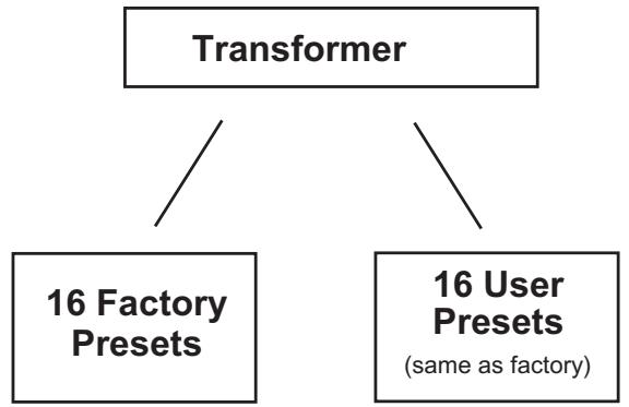
Factory Presets
The 16 factory presets are included to give you a good starting point and to illustrate some of the Transformer's capabilities. Most users will learn from the factory presets and apply what they have learned to the programmable, user presets. When a factory preset is altered it can be stored to a user preset. Any change in a factory setting will be lost (if not stored as a user preset) when the next preset is selected.
User Presets
The 16 user presets come from Peavey loaded with the same presets found in the 16 factory presets. They can easily be "transformed" to your preference and/or saved in the same (or a different) location. It is easy to select between the user and factory presets. Simply press (and quickly release) the User Switch on the front panel of your Transformer to toggle between both. The LED next to the switch will illuminate to indicate you are in the user preset group.
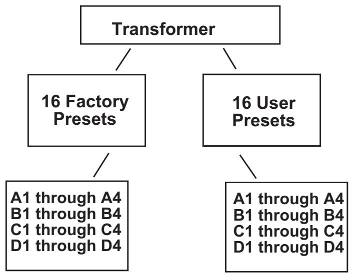
The factory and user presets are each divided into 4 banks (A, B, C and D). Each bank is divided into four individual presets. Therefore, [4 banks] x [4 presets] = 16 (or A1 thru D4). This is demonstrated in the diagram below.
Each preset, factory or user, has primary and secondary settings for gain/EQ, modulation, delay and reverb. These primary and secondary settings do not include amp model, modulation type or delay tempo changes. You can access and edit these settings by placing the PFC 4 footswitch in the EFX Select Mode. That's a multitude of effects/gain combinations. EFX Select Mode is discussed in detail on page 13.
Important!
Now that you have a good understanding of the preset structure it is important that you keep three things in mind while editing and saving presets.
First, you can change any preset (user or factory) and save it to any of the 16 USER preset locations. For example, you may change the Pre Gain level on factory preset A1 and save it to user preset B3. Of course, when you pull up factory preset A1 the Pre Gain value will revert back to its original value and the new value will be stored in the user preset B3. Once changed, the original user settings will no longer be identical to the factory settings.
Second, whenever you reinitialize the Transformer you perform a hard reset. All programmed presets will be deleted and the Transformer will revert back to its original factory and user settings.
Third, every preset has primary and secondary settings accessible by the EFX Select footswitch mode.
AC POWER
There are two features that deal with AC power on the Transformer. Both are located on the left, rear panel of the unit. Next to these features you will find the proper AC line voltage requirement for your particular amplifier. It is important that this requirement be met for your unit's safe and proper use. Refer to the diagram below for the location of these parts.
REAR PANEL
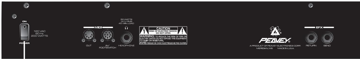
21. REMOVABLE AC POWER CORD (UNDERSIDE OF REAR CHASSIS)

This receptacle is for the IEC line cord (included), which provides AC power to the unit. Connect the line cord to this connector and to a properly grounded AC supply. Damage to the equipment may occur if an improper line voltage is used. (See voltage marking on unit.) Never remove or cut the ground pin of the line cord plug. This unit is supplied with a properly rated line cord. When lost or damaged, replace this cord with one of the proper ratings.
2. POWER SWITCH
- Place this switch in the "ON" position to turn the Transformer on. The LEDs on the front panel and the footswitch (if connected) will illuminate indicating that the unit is on.
FRONT PANEL
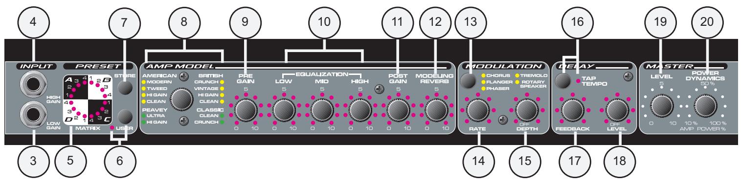
The front panel of the Transformer features all of the user controls necessary to create the sound and response you want. The footswitch, though also a controlling factor, contains only a small portion of the front panel features. The following section describes the front panel features in detail. Where applicable, features associated with the footswitch are noted. When you complete this section you should know the function of each and every knob and jack on the front panel.
INPUT
3. HIGH GAIN INPUT JACK
This is the standard input used for most instrument applications. Most electric guitars will work ideally when plugged into this 1/4" mono input. The High Gain Input is 6 dB louder than the Low Gain Input (4).
4. LOW GAIN INPUT JACK
This 1/4" mono input is provided for instruments with extremely high outputs, which can result in overdriving (distorting) the High Gain Input (3). If both the Low Gain and High Gain inputs are used simultaneously, their levels are both Low Gain.
Preset
5. PRESET MATRIX SELECTOR
This encoder switch provides a means of selecting the active preset. Based on the position of the User Switch (6), the encoder switch can select any preset, user or factory. The matrix is divided into four groups (A, B, C and D) representing the four banks. Positions 1 - 4 and their respective LEDs are labeled in each bank to allow for distinct preset selection. The current active preset is always indicated by the illuminated LED next to its position except when storing. During the Store function the blinking LED shows the destination preset and not the current one. The function of the Preset Matrix Selector can also be performed by the footswitch and MIDI program change commands. Refer to the MIDI/Footswitch section of this guide for an explanation of these functions. For a description of the Transformer preset structure go to page 28.
6. USER SWITCH/LED
The User Switch toggles the Transformer between factory presets and user presets. This function can only be performed on the front panel, not the footswitch. The LED next to the User Switch will illuminate when the user presets are active and the factory presets have been defeated.
7. STORE SWITCH
This switch is used to store presets in specific locations. This may be required after a preset has been altered and/or a new preset location is desired. When a preset is finalized and ready for storage, press this switch once. The active matrix LED will begin to flash indicating the current active preset location. If you desire to keep the new preset stored in its current location, press the Store Switch a second time and the operation is complete. However, if you wish to change the preset location, turn the Preset Matrix Selector to the desired new location. When the flashing LED is in the desired location press the Store Switch again and the preset will be saved in its new spot. This function is only available with the Store Switch.
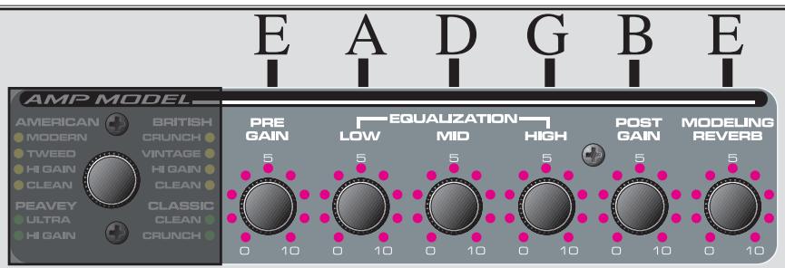
AMP MODEL
8. AMP MODEL SELECTOR
Use this switch to select the amp you wish to emulate. The LEDs surrounding this switch always reflect the active model for the current selected preset. The amp model can be changed at any time by just rotating the selector switch to the desired amp position. If you decide to store the new amp model in the current preset location, simply hit the Store Switch (7) twice.
The following chart describes the various amp model positions and their characteristics:
| Amp Model | Speaker | Description |
| American | ||
| Modern | 112 | High gain, active EQ, mid control shifted to 600 Hz |
| Tweed | 410 | 50's tweed 410 combo |
| Hi Gain | 112 Chrome dome | Hot rodded American-style 112 combo |
| Clean | 212 American | 60's American-style 212 combo |
| Peavey | ||
| Ultra | 412 Peavey | High gain, active EQ, Ultra Plus, 5150 enclosure, mid shifted to 900 Hz |
| Hi Gain | 412 Peavey | 5150® enclosure, 5150/Transtube Bandit® in high gain mode |
| Classic | ||
| Clean | 112 | Peavey Classic® in clean channel |
| Crunch | 112 | Peavey Classic® in lead channel, move T.Dynamics® down for Classic 30 and up for Classic 50 |
| British | ||
| Crunch | 412 Brit. | 70's British amp with master volume |
| Vintage | 212 Brit. | 60's British amp, blues combo |
| Hi Gain | 412 Brit. | 80's Modified British with master volume |
| Clean | 212 Brit. | 60's British clean 212 combo |
9. PRE GAIN
The Pre Gain control sets the input level to the Transformer. Adjusting this control fully clockwise will result in maximum gain. This control is often used to adjust the amount of distortion present in the signal since it can raise the input level to an overdriven state. When using the footswitch in EFX Select Mode, the Pre Gain can be toggled between two settings by pushing the Boost Footswitch (27).
10. EQUALIZATION
The three-band EQ found on the Transformer "transforms" in conjunction with the position of the Amp Model Selector (8). This is understandable when you consider that all amps have different EQ circuitry in them. Some have active EQ and some have passive EQ. Some mid EQ's have a center frequency of 1 kHz and others may be lower or higher. The Transformer emulates the EQ and even the EQ pot tapers for the particular amp it is modeling. Simply put, adjusting the EQ on the Transformer is comparable to adjusting the EQ on the amp you are emulating. This aids the Transformer in a successful reproduction of the amplifier you desire. Refer to the Amp Model Chart on page 8 for a description of the EQ characteristics of each amp model. When using the footswitch in EFX Select Mode, the EQ settings can be toggled between two settings by pushing the Boost Footswitch (27).
11. POST GAIN
The Post Gain sets the overall volume level for an individual preset. When using the footswitch in EFX Select Mode, the Post Gain can be toggled between two settings by pushing the Boost Footswitch (27). This is a useful function when a sudden change in level is desired within the same preset. Refer to the MIDI/Footswitch section and the Application Notes for more information on this feature.
The Post Gain should not be confused with the Master Level (19) control which sets the overall volume level of the Transformer as a unit. The Master Level affects all presets and the Post Gain only affects individual presets.
12. MODELING REVERB
This control determines the amount of reverb present in the overall signal. The reverb utilized by the Transformer alters its tone in relation to the Amp Model Selector (8) position. When using the footswitch in EFX Select Mode, the Reverb can be toggled between two settings by pushing the Reverb Footswitch (30). Those two settings can represent any position on the knob, including off (fully counterclockwise). Refer to the MIDI/Footswitch section and the Application Notes for more information on this feature.
MODULATION
13. MODULATION SWITCH
The Modulation Switch selects which type of modulation effect is active. You may select between Chorus, Flanger, Phaser, Tremolo and Rotary Speaker. This function is not available from the footswitch.
14. RATE
The Rate control determines the sweep rate of the modulation effect that is selected by the Modulation Switch (13). Rotating this control clockwise will result in an increased rate. The Rate and Depth (15) settings work together to determine the overall modulation effect. When using the footswitch in EFX Select Mode, the Rate can be toggled between two settings by pushing the Modulation Footswitch (28). Those two settings can represent any position on the knob. Keep in mind, both the Rate and Depth (15) are toggled simultaneously. Refer to the MIDI/Footswitch section and the Application Notes for more information on this feature.
15. DEPTH
The Depth control determines the sweep depth of the modulation effect that is selected by the Modulation Switch (13). Place this control in the full counter-clockwise position to turn the delay effect off. Rotating this control clockwise will result in an increased depth and/or mix.
The Rate (14) and Depth settings work together to determine the overall modulation effect. When using the footswitch in EFX Select Mode, the Depth can be toggled between two settings by pushing the Modulation Footswitch (28). Those two settings can represent any position on the knob, including off. Keep in mind, both the Rate (14) and Depth are toggled simultaneously. Refer to the MIDI/Footswitch section and the Application Notes for more information on this feature.
DELAY
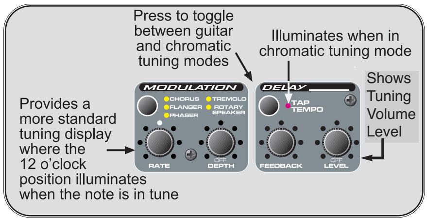
16. TAP TEMPO BUTTON/LED
The Tap Tempo button sets the delay time to match that of a certain tempo. Pressing the button several times (at least two) in unison with the desired tempo will reset the delay tempo. A Tempo LED is located next to the Tap Tempo Button to provide a visual representation of the delay rate. This function can also be performed on the footswitch by tapping the Tap Tempo Footswitch while in the EFX Select Mode. Refer to the MIDI/Footswitch section and the Application Notes for more information on this feature.
NOTE: You can use the two tap switches (footswitch and front panel) together alternating between foot and hand to get very short delay times. Pressing the two almost simultaneously will produce this effect.
17. FEEDBACK
This control determines the number of repeats or the "decay time" for the delayed signal. Turn the knob clockwise to increase the feedback setting. When using the footswitch in EFX Select Mode, the Feedback can be toggled between two settings by pushing the Delay Footswitch. Those two settings can represent any position on the knob. Keep in mind, both the Level and the Feedback are toggled simultaneously. Refer to the MIDI/Footswitch section and the Application Notes for more information on this feature.
18. LEVEL
This control determines the relative volume of the delayed signal. Turn the knob clockwise to increase the amount of delayed signal found in your overall sound. Place this control in the full counterclockwise position to turn the delay effect off. When using the footswitch in EFX Select Mode, the Level can be toggled between two settings by pushing the Delay Footswitch. Those two settings can represent any position on the knob, including off. Keep in mind, both the Level and the Feedback are toggled simultaneously. Refer to the MIDI/ Footswitch section and the Application Notes for more information on this feature.
MASTER
19. LEVEL
Use this control to adjust the overall (global) gain of the Transformer. This control setting is not linked in any way to a stored preset. Adjust the Level control to various playing situations such as different room sizes or whenever an overall level change is desired. Changes in this control setting will bring up or down all preset levels proportionally. It will not affect the volume of the effects loop.
20. POWER DYNAMICS
This is the famous Peavey T.Dynamics found throughout the award winning TransTube Series amplifier line. The Power Dynamics control adjusts the power level of the amplifier from 10 percent to 100 percent power. When set to lower settings, the power compression simulation will be much more pronounced.
TRANSFORMER 212
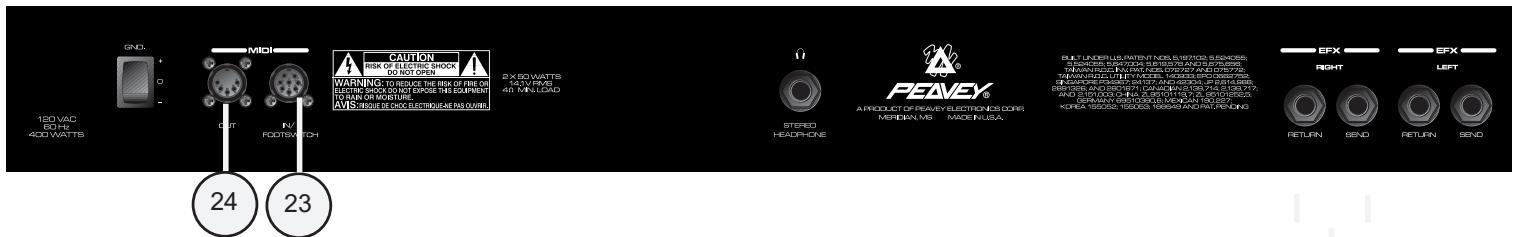
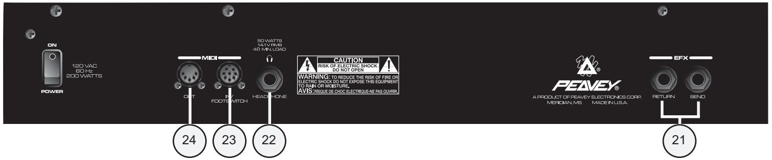
EFX
21
21. SEND/RETURN
This pair of 1/4" jacks supplies an effects SEND and RETURN path for the preamp signal. Connect the SEND jack to the input of external, low-level, signal processing equipment (effects). The SEND jack is a stereo (TRS) jack allowing connection to stereo outboard effects as well as a second combo amp like the Transformer. Return the signal from your external equipment to the RETURN jack. This is known as an Effects Loop since the signal exits your amp (send) and loops (return) back to it. When using external effects in stereo you may wish to return the left signal back to the RETURN jack and send the right signal to an additional outboard amplifier or a second Transformer. The TRS SEND jack is wired with the tip as the left signal (which goes to the speaker) and the ring as the right signal. When a mono plug (standard guitar cable) is partially inserted to the first click of this jack, it can be linked to the input of an auxiliary amp to achieve stereo sound. Refer to the Recommended Hookup Diagram on page 12 for more info on using this feature. Also see page 22 to find out how to switch the outputs to stereo mode.
HEADPHONE
22. HEADPHONE JACK
This stereo 1/4" jack accepts a standard pair of headphones. Using this jack defeats the output to the speaker making it ideal for quiet practice applications. Although the signal is sent through a stereo connector, the signal is mono and the sound heard in the left earpiece will be a duplicate of that heard in the right.
MIDI
23. MIDI IN/FOOTSWITCH
The MIDI In eight-pin DIN is used to receive MIDI commands from an external MIDI device or controller. The eight-pin DIN connector will accept both five-pin standard MIDI cables as well as Peavey's eight-pin MIDI/Communication combo cable. By using the eight-pin cable, this DIN connector provides the connection and power for the PFC 4 footswitch (supplied). Refer to the MIDI/Footswitch section and the Application Notes for more information on this feature.
Transformer 112 Recommended Hookups
Mono operation with MIDI Controlled Effects- Connecting to outboard processors
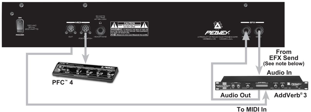
NOTE: Use a mono shielded patch cable for both audio connections. Insert the plugs into the Transformer 112 fully. Use a standard MIDI cable to connect the Transformer 112 to you MIDI controlled effects device.
Stereo Mode - Connecting to an external powered speaker and the foot controller
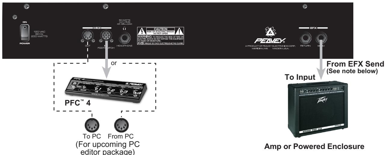
NOTE: The EFX Send is a stereo 1/4" jack. A mono 1/4" patch cable will be inserted into this jack, only to the first click. This supplies the amp or powered enclosure with one side of the stereo signal and the Transformer 112 with the other. Inserting the patch cable connector completely into the plug will not harm the amp but will provide the amp or powered enclosure with an identical signal as the Transformer 112. This produces a mono sound instead of stereo.
Stereo Mode with External Effects - Connecting to an external powered speaker and the foot controller
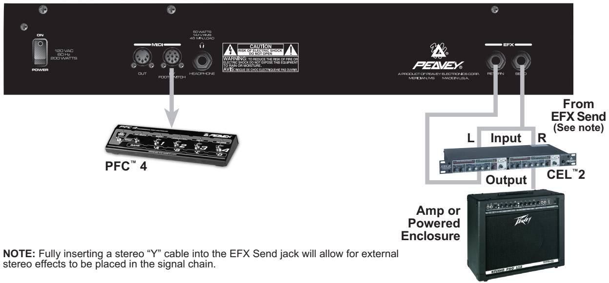
NOTE: Fully inserting a stereo "Y" cable into the EFX Send jack will allow for external stereo effects to be placed in the signal chain.
Transformer 212
Recommended Hookups
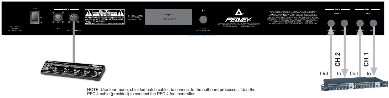
Stereo operation with external effects- Connecting to outboard processors
Stereo operation with two Transformer 212 units- Linking two Transformer 212s
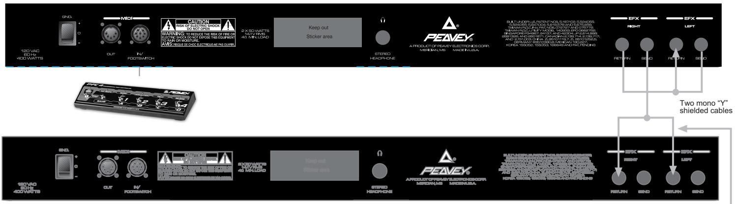
NOTE: The top unit is considered the master unit in this diagram. The bottom unit is the slave unit. Adjust the Master Volume of the top unit to control the level of both units. Use two shielded mono "Y" cables to connect the two units. Use the PFC 4 cable (provided) to connect the PFC 4 foot controller.
NOTE: A standard patch cable may be used here instead of the "Y" cable shown. Simply patch to the front input of the unit for some interesting effects doubling. Be sure to balance the Master Volume controls of the two units (if desired), since both come into play using this configuration.
24. MIDI OUT
The MIDI Out five-pin DIN can be used as both a standard MIDI Thru and/or MIDI Out jack. Program changes sent to the Transformer via the MIDI In jack are echoed thru the MIDI Out. Refer to the MIDI/Footswitch section and the Application Notes for more information on this feature.
MIDI/FOOTSWITCH SECTION
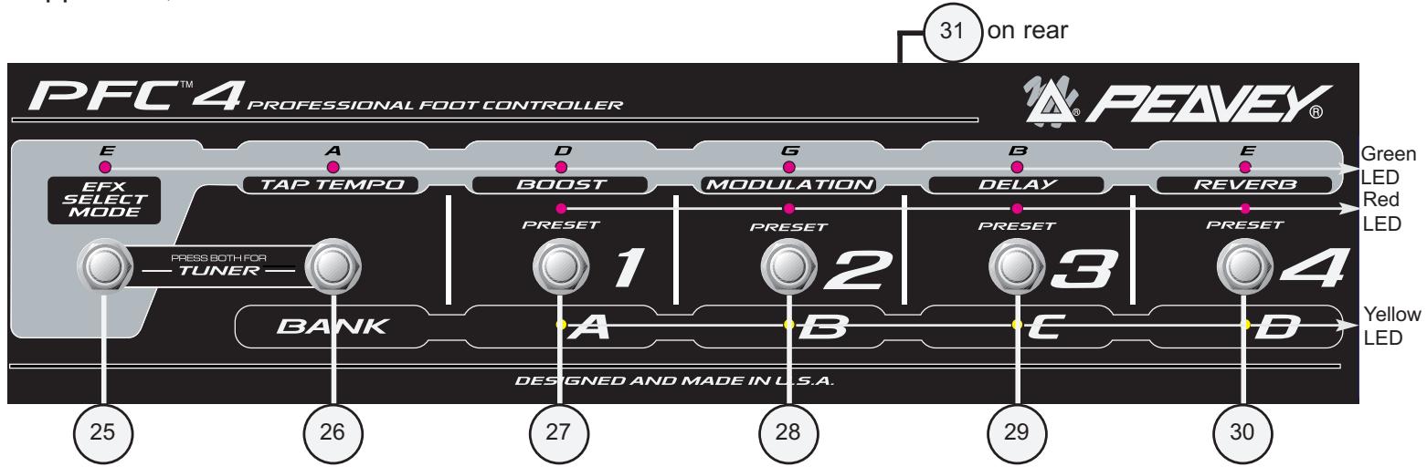
The PFC™ 4 Professional Footswitch included with the Transformer 112 is state of the art. Because the PFC 4 has variety of easy to use functions, the user has access to bank and preset selection, individual effects manipulation, tuner and gain boost. The following section describes each feature of the footswitch as well as a short Transformer 112 MIDI primer.
The PFC 4 operates in four different modes: Tuner Mode, Preset Mode, Bank Select Mode and EFX Select Mode. When the Transformer 112 is first powered up the PFC 4 selects the Preset Mode by default. The numerous buttons on the PFC 4 perform different functions based on the current mode. The current mode is dependent on the condition of the EFX Select Mode Button (25) and the Bank Mode/Tap Tempo Button (26). Therefore, the following section will display the different modes and a description of how each button of the footswitch functions in that mode. If a particular button is not listed under a mode then that button is not applicable. The Tuner Mode does not affect the various functions of the PFC 4. It is explained in the Tuner section of this guide. The remaining modes use color-coded LEDs on each footswitch button to help distinguish its current function. Where applicable, these LED colors and indications are noted.
PRESET MODE
The Preset Mode (default) allows you to select an individual preset within the current bank. When in Preset Mode, the current bank is indicated by an illuminated yellow LED on the footswitch. If the yellow LED is flashing you are in Bank Select Mode. (See Bank Select Mode, this section.)
From the Preset Mode, pressing the following buttons on the footswitch will render the listed result. Refer to the Footswitch diagram on page 17 for numerical/feature references.
Pressing button #25 selects the EFX Select Mode and exits the Preset Mode (see EFX Select Mode, this section). Pressing button #25 again returns you to the Preset Mode.
Pressing button #26 selects the Bank Select Mode and exits the Preset Mode (see Bank Select Mode, this section). Pressing button #26 again returns you to the Preset Mode.
Pressing buttons #27 through #30 select the preset in the current bank and illuminate the red Preset LED.
The Green LEDs dimly indicate that the effect (written below the LED) is either in primary or secondary position as selected in the EFX Select Mode. (See EFX Select Mode, this section).
The Red LEDs indicate the current preset (1,2,3 or 4).
The Yellow LEDs indicate the current bank (A,B,C or D).
BANK SELECT MODE
Pressing the Bank Select Button (26) from the Preset Mode enters the Bank Select Mode. The Bank Select Mode allows you to select an individual preset bank (A,B,C or D). A flashing yellow LED indicates the current selected bank and that you are in Bank Select Mode.
From the Bank Select Mode, pressing the following buttons on the footswitch will render the listed result. Refer to the Footswitch diagram on page 17 for numerical/feature references.
Pressing button #25 selects the EFX Select Mode and exits the Bank Select Mode. (See EFX Select Mode, this section.)
Pressing button #26 will return you to the Preset Mode.
Pressing buttons #27 thru #30 select the bank and illuminate the yellow Bank LED.
The Green LEDs stay the same as they do in the Preset Mode. (See Preset Mode, this section).
The Red LEDs stay the same as they do in the Preset Mode, except in this mode they indicate the current preset number and the preset number (not bank) you will be relocated to once the new bank is selected. For example, changing banks while currently at preset A4 will only allow you to go to the A4, B4, C4 or D4 positions from the Bank Select Mode. This can be changed to go to A1, B1, C1, D1, or wait for your selection. (See Hot Key Chart page 22.)
The Yellow LEDs indicate the current bank (A,B,C or D) by flashing on and off.
EFX SELECT MODE
Pressing the EFX Select Button (25) from the Preset or Bank Select Modes enters the EFX Select Mode. The EFX Select Mode allows you to toggle between primary and secondary preset parameters. The green EFX Select Mode LED illuminates to indicate that this mode is active. To exit the EFX Select Mode, press the EFX Select Button (25) a second time.
From the EFX Select Mode, pressing the following buttons on the footswitch will render the listed result. Refer to the Footswitch diagram on page 17 for numerical/feature references.
Pressing button #25 will return you to the Preset Mode.
Pressing button #26 sets the delay tempo. It must be pressed more than once to record a delay rate change. It is possible to use this button in conjunction with the Tap Tempo Button (16) on the front panel of the Transformer 112 in order to achieve rather short delay times.
Pressing button #27 toggles between the primary and secondary boost settings.
(See EFX Select Mode in the Application Notes page 16.)
Pressing button #28 toggles between the primary and secondary modulation settings. (See EFX Select Mode in the Application Notes page 16.)
Pressing button #29 toggles between the primary and secondary delay settings.
(See EFX Select Mode in the Application Notes page 16.)
Pressing button #30 toggles between the primary and secondary reverb settings.
(See EFX Select Mode in the Application Notes page 16.)
The Green LEDs stay the same as they do in the Preset Mode. (See Preset Mode, this section.) NOTE: The Tap Tempo LED flashes to indicate the current delay rate.
The Red LEDs stay the same as they do in the Preset Mode, except in this mode they become more dim in order to not confuse you during the EFX Select process.
The Yellow LEDs indicate the current bank (A,B,C or D) of the current preset. The current bank's LED will become dim in order to not confuse you during the EFX Select process.
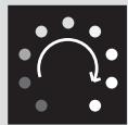
TUNER MODE
Pressing both the EFX Select Button (25) and the Bank Select Button (26) from any mode (except from the Tuner Mode itself) will enter the Tuner Mode. The four yellow LEDs will light dimly to indicate the Tuner Mode is acitve and awaiting a signal. This section will only describe the footswitch functions of the tuner. Refer to the beginning of the Application Notes to get a more thorough explanation of the Transformer's tuner function.
From the Tuner Mode, pressing any footswitch button will exit the tuner and return to the previous mode and preset.
The Green LEDs indicate the current note the tuner is tracking. When in chromatic mode, if the played note is not an E, A, D, G or B then the tuner will light the two green LEDs that the played note falls between.
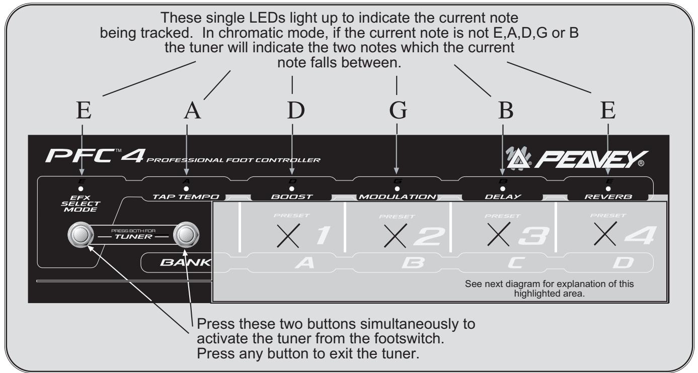
The Red LEDs work in conjunction with the yellow LEDs to form a ring. When a note is being tracked, the red and yellow LEDs illuminate progressively in a circle. If the LEDs light in a counter clockwise rotation then the note is flat. If the LEDs light in a clockwise rotation then the note is sharp. If they rotate quickly then you are far from having the note tuned. If they rotate slowly then the note is near its tuned state. When the note is tuned, all red and yellow LEDs will illuminate simultaneously, making it very obvious.
The Yellow LEDs always light up dimmly when the tuner is first activated. Once a note is played they act as the red LEDs do above.
31. REMOTE CABLE CONNECTOR
This eight-pin DIN is used to transmit and receive MIDI commands to and from the Transformer MIDI In/Footswitch (23). Certain functions, such as the tuner, are also communicated through this connection. Only Peavey's eight-pin MIDI/Communication combo cable (included) should be used for this connection.
Transformer
Application Notes
This section provides short tutorials demonstrating various features and operation scenarios. Since tuning is generally done before playing, let's learn how to use the built-in strobe-style tuner. You should complete steps 1 - 6 of the Quick Start section on page 3 before beginning this tutorial.
Tuner Notes
Your Transformer features a dual-mode tuner which can be viewed from both the front panel of the unit and/or the footswitch. The two tuner modes include guitar and chromatic. Let's first take a look at how the front panel and footswitch "transform" to display the tuner functions.
Front Panel
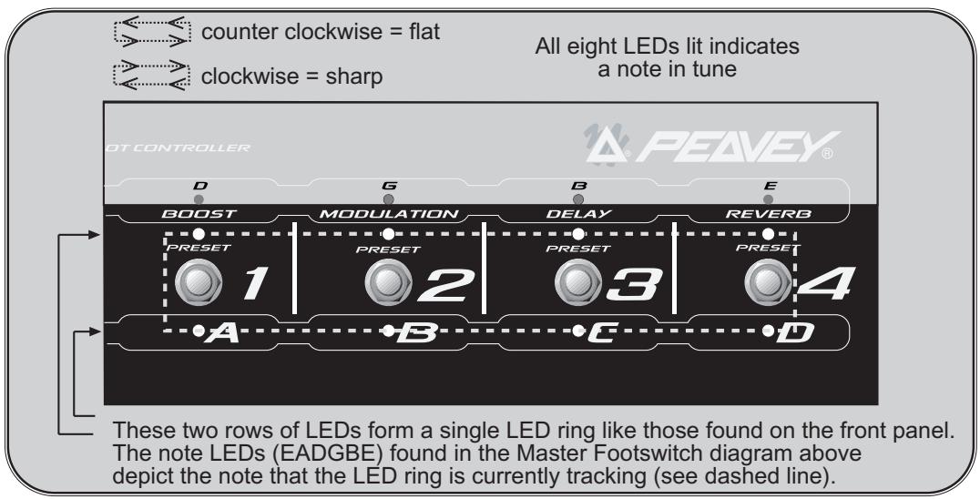
You may access the tuner function from any mode while the amp is on by pressing both the STORE and USER buttons simultaneously. The default tuner mode is the guitar mode. (See Guitar/Chromatic Modes on next page). The diagram below depicts the functional transformation that occurs to the front panel LEDs when the tuner is activated. In the diagram, the letters listed above the LED rings correspond to the six strings of a six-string guitar tuned to a standard tuning.
TUNER/LED TRANSFORMATION ON FRONT PANEL:
The LED ring works like a strobe-type tuner.
When the LEDs illuminate in a counter clockwise direction, the note is flat. When the LEDs illuminate in a clockwise direction, the note is sharp.

Counter clockwise = note is flat
The faster the rotation the more out of tune.
Clockwise = note is sharp
When the LEDs illuminate to form a star shape with no rotation, the note is in tune.

No rotation (star shape) = note is tuned
NOTE: The same front panel features/functions are used for both the guitar and chromatic modes.
Footswitch
The footswitch, when plugged in, works simultaneously with the front panel. Since it doesn't have in common the LED rings that the front panel has, the footswitch must do some transforming of its own. Refer to the diagrams below to see which LEDs and switches play a role in tuner use.
To access the tuner function from the footswitch, press both the EFFECTS SELECT MODE button and the BANK SELECT MODE button simultaneously. The footswitch indicates that it is in Tuner Mode by dimly illuminating all four yellow bank LEDs. In the diagram below, the letters listed above the footswitch LEDs correspond to the six-strings of a six string guitar tuned to a standard tuning. Unlike the front panel, the footswitch is labeled E, A, D, G, B and E (top left to right) to aid in quick, remote tuning. These labels designate the note represented by the green LED below it. Upon striking a note, a green LED will illuminate just as the LED ring did in the front panel description. Though the green LEDs function in both guitar and chromatic tuning modes, they will respond differently. See the following section for a description of the two tuning modes.
Master Footswitch Tuner Indicators/Controls:
Secondary Tuner Indicators:
NOTE: Four illuminated yellow LEDs and no illuminated preset (red) LEDs indicates that the tuner is waiting for a note to be played.
Tuning Modes
While in the Tuner Mode, press the Tap Tempo button on the front panel to toggle between the guitar and chromatic tuning modes.
In the Guitar mode, the built-in tuner acts much like a standard, auto guitar tuner. It always searches for the standard guitar notes (EADGBE) and automatically selects the notes for you. In other words, you don't have to select a note for your Transformer to find, it tracks the current note automatically. The note indicated (lit up) by the Transformer is the closest standard tuning note in relation to the current note being played. The Transformer will indicate whether the note is sharp or flat by strobing the illuminated LEDs right or left respectively.
In the Chromatic mode, the tuner tracks all notes whether they are standard tuning or not. If you were to play an F# on the low E string, the tuner would track that F# even though it is not a standard open string tuning for a guitar. This is a handy feature which makes the built-in tuner functional for open tunings as well as tuning a variety of other instruments. The display indicates sharp and flat notes the same as it does in the Guitar mode. The main visual difference in the display occurs when you hit a note such as the F#. The display only has provisions to indicate E,A,D,G, B and E. Therefore, the tuner will light up both the E and A positions in order to indicate that the note is somewhere between an E note and an A note. The Guitar mode cannot do this since it tracks the F# note as a G note that is flat.
The Chromatic tuning mode is octave sensitive. Using the F# scenario from above, this becomes easy to explain. If an F# is played on the D string (instead of the low E), the D and G positions illuminate to indicate that the note is sharp for the D string. Whenever you see multiple green LED's lit up on the footswitch while tuning, these same positions will light up on the LED rings found on the front panel. See the Transformer Tricks page for some power user tuning suggestions!
NOTE: If you want the tuner to remember your settings, press STORE once while in Tuner Mode.
TOP SECRET
Transformer Tricks
This section is for the power user. If you are experienced with the traditional combo guitar amp, this section is for you! The Transformer earns its name through the incredible flexibility it possesses. In this section Peavey engineers provide you with many hidden functions not advertised or screened on the front of the unit. These are strictly free functions that were used to aid in the actual design of the Transformer. In order to prevent confusion, these functions were not listed in the features list for this product.
Swap Cabinets
One of the most unique hidden features on the Transformer is the ability to change speaker cabinets for the various amp models. For example, if you're modeling a popular American 212 amp and you'd like to hear what that same amp would sound like with a 412 enclosure, it's easily accomplished.
- Select the desired preset number using the Preset Matrix Selector (5).
- Select the desired amp model using the Amp Model Selector (8).
- Press and hold down the User Switch for full second (6).
- Select the desired speaker cabinet (refer to chart on page 8 using the Amp Model Selector.
- Release the User Switch.
You have now created your own combination amplifier! Adjust the EQ and gain controls to your taste. Then, add in some effects for more dynamics. Once you are happy with the tone and levels you can save this new combination as a preset by pressing the STORE button twice. You may also save this preset to a different location by pressing the STORE button only once, selecting the desired preset location and then pressing the STORE button once again.
With this feature of the Transformer you are able to mix and match virtually any amp and enclosure available on the market in any way you desire.
Sweet Sweep Freeze
This is an unobtrusive feature that is simple to use. This feature is only available for patches that utilize the Phaser or Flanger modulation effect. These two effects function from a process called comb filtering, which effectively runs your guitar signal through a filter (pseudo EQ) that is sweeping. The rate at which it sweeps is determined by the Rate (14) control. The Sweet Sweep Freeze allows you to stop the filter from sweeping at any part in its sweep cycle, preserving the tone from that position.
Imagine that you are using a lot of Phaser effect with a very slow Rate setting. You can actually hear the effect as it makes a long "swish" sound. What it is actually doing is cutting the level to a certain frequency, similar to pulling down the slider on a graphic equalizer. However, the frequency it cuts is constantly changing or sweeping. This would be comparable to grabbing the sliders on an equalizer and moving them up and down quickly from left to right and then right to left. Now imagine that whole sweep cycle as the word "swish". During the "sw" portion of the swish cycle, the high frequency content of your guitar tone is washed out and reduced to almost nothing. As you approach the "wis" portion of the swish cycle, your mid frequency content becomes more apparent. A slight increase in highs can also be noted. As the cycle approaches its end or the "sh" portion, both the highs and mids are very evident in your guitar tone.
This effect causes your tone to sweep in and out from a somewhat mellow, rolling tone to a more dynamic, present tone. Sweet Sweep Freeze allows you to stop the sweep anywhere in its cycle and freeze the tone at a desired spot. This is really cool since it can all be done from the footswitch once some specific settings are made on the front panel.
- Pull up a preset with the Flanger or Phaser modulation effect in the patch [or switch to it with the EFX Select Modulation Switch (28)].
- Place the footswitch in Effects Select Mode by pressing the EFX Select Mode Button (25).
- If the green Modulation LED (on footswitch) is not lit press the Modulation Button (28) once to select the secondary position. If it is lit move to step 4.
- Adjust the Depth (15) control on the front panel for the amount of effect you desire.
- Adjust the Rate (14) control on the front panel to the desired rate or speed.
- Press the Modulation Button once to turn the LED off and change the effect to its primary settings.
- Turn the Depth setting to the same setting as in the secondary mode but turn the Rate all the way down, effectively turning the sweep off. This leaves the effect (filter) in the signal path but doesn't allow it to sweep. Put another way, it is frozen.
- Press the Modulation Button once more to activate it's secondary (sweeping) setting.
- You should be able to press the Modulation Button at this time and toggle between the your desired modulation effect and frozen filter position.
Notice as you play through the Transformer, toggling the modulation effect between primary and secondary settings, the Sweet Sweep Freeze function freezes the filter at whatever position it was in the cycle and maintains that tone until you activate the effect again. Upon activating the effect, the cycle picks back up where it left off.
The Sweet Sweep Freeze effects is especially useful because it allows you to punch in and out of the modulation effect without hearing the drastic difference in guitar tone that is reminiscent of the old phaser/flanger effects. Since the guitar stops the sweep and plays the sound that was last heard there, effectively, is no tone change. In addition, it allows you to wait for a killer tone to come up in the sweep cycle and then lock on to it immediately. The Transformer will not remember that freeze point for future recalls of that preset. This is simply a means of freezing a tone within an active preset. Here's a tip for freezing tones. Before switching the modulation effect off and freezing the tone, it is easier if the Rate is set to about the 9 o'clock position and the Depth to about the 12 o'clock position. This allows for bigger and longer sweeps, giving you more time to freeze the signal.
Two Steps to Half-Step Tuning
The Transformer also allows you to tune your guitar a half step lower (E_b) . This E_b tuning is very popular and can be easily mastered using this quick function.
- Press the STORE and USER buttons simultaneously to enter the Tuner Mode.
- Press the USER button once more to "Transform" the tuner from E tuning to E . (If the USER LED is lit, the E tuning is already enabled.)
All LED rings (the entire tuner) have been shifted a half step to measure for E_b tuning. The tuner will remain in E_b tuning until you exit and must be put back into E_b tuning if so desired during the next tuning session. (Unless you press STORE while in the tuner, which will store your tuner settings.)
Once a Gain
This feature allows you to get another boost of gain from your Transformer. If a single-button footswitch (Peavey part #5100) is inserted into the Low Gain input on the front panel of the amp (with a guitar plugged into the High Gain input) you can access an extra gain boost rather comfortably. This is especially useful if you have two guitars with different output levels. The footswitch must be the push on/push off type and utilize a shielded cable. A momentary switch of this nature is not recommended. Simply press the button on and off while playing to determine which position has the higher gain.
*See the Transformer Default and Hot Key Chart on page 22 for more hidden features and tweaks.
Transformer
Default and Hot Key Chart
Refer to the chart below. The three tweak modes (Patch, Global and Tuner) are listed on the top row of the chart. The column to the left lists the control and/or buttons found on the front panel of your Transformer. To enter one of the three tweak modes, refer to the (note) just below it. When a front panel feature from the left column is used while in one of the three tweak modes, the feature may take on a new function. This new function is listed in the adjacent tweak mode columns. Simply match the row of the feature with the column of the desired or current tweak mode. Where a dash (-) is placed there will be no change in the function of that particular feature.
| Control or Button | Patch Tweak (hold USER button 1 sec.) | Global Tweak (hold STORE button for 1 sec.) | Tuner Tweak (When Tuner is active) |
| Preset | - | MIDI Channel | [Exit Tuner] |
| Store | - | - | Store Tuner Treaks |
| User | - | User on Powerup | E, mode |
| Model | Cabinet | - | [Exit Tuner] |
| Pre | - | - | - |
| Bass | - | - | - |
| Mid | Mid Shift Frequency | - | - |
| Treble | - | - | - |
| Post | - | Bank Select Style | - |
| Reverb | - | Footswitch All-Info | - |
| Mod Select | - | - | [Exit Tuner] |
| Rate | Flanger Delay Time | - | - |
| Depth | Flanger Feedback | Mono/Stereo | - |
| Tap | Delay Treble Rolloff | - | Chromatic Mode |
| Feedback | Delay Time Scale | Noise Gate Sensitivity | - |
| Level | Delay Stereo Separation | Noise Gate Threshold | Tuner Volume |
Details:
Patch
Mid Shift Frequency - Range depends on model. Active EQ (Peavey Ultra / Am. Modern) goes from 300 Hz. to 940 Hz. in 20 Hz. steps.
Flanger Delay Time will go from 0.2 ms to 5.0 ms in 0.2 ms steps. (Default is 2.0 when flange selected.)
Flanger Feedback will go from 0 to 96% in steps of 4. (Default is 74 with flange selected.)
Delay Treble Rolloff default. (LED off) Switch on for darker delay tone more like a tape echo.
Delay Time Scale will be reset to 0 [12:00] after a tap function. +/-50% will be available to tweak after that.
Delay Stereo Separation ranges from 0 to 100ms in 4 ms steps. (This applied to right side delay signal, not to dry signal.) Default = 20 ms.
Global
MIDI Channel will go from 1 (Preset Matrix Selector LED A1) to 16 (Preset Matrix Selector LED D4). Footswitch/SysEx will always work. Channel messages will be sent with this channel, and will be ignored on receive unless on this channel. Default = MIDI channel 1.
User on Powerup - default is Factory patches on powerup - LED off. Turn on for USER patches on powerup.
Bank Select Style will be
0 = (default) go to same patch in new bank [7:00/min]
1 = go to patch #1 in new bank [12:00]
2 = wait for user to press a preset footswitch before switching (current red blinks) [5:00/max]
Footswitch All-Info will be:
0 = Only shows LED's of current mode (either greens or reds/yellows.) Less info, less confusing. [7:00/min]
1 = (default) Shows dim LED's for the inactive mode (e.g. greens when NOT in EFX mode.) [12:00]
2 = Shows all LED's bright in either mode. Good for seeing everything in brighter light where the dim level could wash out. [5:00/max]
Mono / Stereo - defaults to Mono [7:00/min]. Set to 5:00/max] for stereo when using the TRS stereo FX send jack.
Noise Gate Sensitivity - Increase this to get more gating effect. Reduce to get a gentle reduction.
Noise Gate Threshold - Set this while the guitar volume is up but the strings are muted. Turn Sensitivity up all the way, then turn this up until you hear the noise drop out. Then go up just a bit more (one or two LED changes). Then reduce the sensitivity to taste. This should only have to be changed if the incoming noise level changes, e.g. changing guitars or environments. Turning this all the way down disables the noise gate.
Tuner
Store Tuner Tweaks - Tuner will not remember your preferences unless you save them. (Just press once).
E, mode - Press the USER switch to toggle between E and E, mode. The LED will be lit for E, mode. All notes are moved up on the display - even in chromatic mode. We offer this since E, tuning is so popular among guitarists.
Chromatic mode - Press the TAP switch to toggle between guitar and chromatic mode. The LED will be lit for chromatic mode. We offer this so you can use open tunings and not have to bring a separate tuner.
Tuner Volume - Defaults to 12:00 position. Turn up or down to change the bypass volume level while tuning. Turn all the way down for silent tuning.
Transformer MIDI Implementation
The Transformer is designed to be an all-in-one guitar amplification system using the PFC 4 footswitch. However, the numerous other uses for the MIDI jacks will be discussed here. We'll start with the simpler stuff, and move on to the more complicated stuff later.
MIDI Channel on the Transformer
The Transformer's MIDI channel is 1 by default (after re-initialization). This means that any channel messages that are received on another channel are ignored, and any channel messages that are generated are sent on this channel. To change the channel, hold the STORE button down for at least a second, and (while holding) select channel 1 - 16 using the Preset Matrix selector.
MIDI Out as a MIDI Thru
Most likely, you'll be using the PFC 4 to drive the MIDI In, since it adds so much to the usability of the amp. If you decide to link another Transformer up for stereo operation, you can have the second one be slaved to the first one's PFC 4 by connecting a MIDI cable from the first's Out to the second's In. They will track program changes, EFX mode changes, TAP tempo, other preset edits, etc. Even if the audio link is from the first's effects send to the second's effects return, it's still useful to have the same presets in the second amp and link them since the Amp Model selection (which changes per preset) affects the voicing of the power amp.
The MIDI Out jack will echo virtually all commands that arrive at the MIDI In (with the exception of certain Sysex messages meant for the Transformer), so it can be used in the middle of a MIDI chain when driving a rig from another MIDI source, instead of using the PFC 4. This is called a "soft" thru, which means it is dependent upon the software (processing power and MIDI buffer) of the unit. A "hard" thru refers to a jack labeled "Thru" and not "Out" or "Out/Thru." It's usually accompanied by a separate MIDI In and Out, and it's usually in the middle. Most importantly, it's directly driven from the In jack, so it is not dependent on the software to do the echoing work. So if your other MIDI units are "three-jack" units, it may be wise to put the Transformer at the end of the chain, since a soft thru is never quite as bulletproof as a hard thru.
Preset Synchronization with an External Effects Unit
You may have a programmable effects unit with a MIDI In that you want to use in the Transformer's effects loop. If you want this unit to change presets when the Transformer does, connect a MIDI cable from the Transformer's MIDI Out to the MIDI In of the effects unit. Then the first 16 presets in the effects unit will be aligned with the 16 presets in the Transformer.
For this to work, the MIDI channel of the effects unit must either be set to OMNI, or match that of the Transformer.
Preset Backup
You can back your presets up to a computer, sequencer, or other type of MIDI librarian/recorder. You can also transfer them to another Transformer! Connect a MIDI cable from the Transformer's MIDI Out to the MIDI In of the recording device. Prepare the recording device or software program to receive data. (In the case of transferring to another Transformer, it just needs to be on.) You are now ready to send the presets.
To initiate the transmission manually, hold the amp's TAP button and then press the MODULATION Select button. The six Amp Model LED rings (Pre Gain through Reverb) should go off for a second or two to verify the operation. When they come back on, the operation is done.
NOTE: The size of the System Exclusive preset dump is 1000 bytes.
If your recording device can send a request string to automate this operation, the string can be found in the SysEx table below. Another cable will have to go from the Recorder's Out to the Transformer's In for this to work. Sending that string to the Transformer will initiate the dump operation.
To dump globals:
hold TAP and press STORE
To dump a single preset:
hold TAP and press USER
Channel Messages
The Transformer will accept (and echo) the following channel messages when they are sent on its MIDI Channel. (Values are shown in hexadecimal.)
- Program Change - Cx nn where x = MIDI channel - 1, nn = 00-0F for presets A1 - D4
- Bank Select - Bx 20 nn where x = MIDI channel - 1, nn = 00 for factory, 01 for user
- Main Volume - Bx 07 nn where x = MIDI channel - 1, nn = 00-7F for mute to full
NOTE: The Main Volume will be located after the preamp and EQ and before the time-based effects.
Other channel messages will be echoed to the MIDI Out, but will not affect the Transformer.
The Transformer will generate the following channel messages on its MIDI Channel:
- Program Change (as shown above) - whenever a preset change is initiated by front panel or PFC4.
- Bank Select (as shown above) - whenever the MATRIX bank is toggled from/to Factory to/from User.
System Common and System Real Time Messages
The Transformer will echo these messages to the MIDI Out when received. None will be generated by the Transformer.
System Exclusive Messages
The Transformer is equipped with an extensive MIDI SysEx implementation. In addition to simple preset dumps and preset sharing via the Internet this enables the amp to be programmed remotely by a computer program or hardware editor like the Peavey PC1600X.
All of the Transformer's SysEx messages start with a common header and end with an End of Sysex [EOX] byte. The table below shows the "unique" section (including the command and optional data) of each message that falls between the header and the EOX.
Here is the common part, along with descriptions of each byte's purpose:
F0 - Start of SysEx [SOX]
00
00
1B - Peavey Manufacturer ID = 00 00 1B
10 - Transformer Product ID
00 - Reserved for future use (keep fixed at zero)
CMD - Command byte that defines which SysEx message it is
-data>- Optional data
F7 -End of SysEx [EOX]
NOTE: Each time a preset is recalled, it is first loaded into a RAM buffer that we call the Edit Buffer (could also be called "current preset"). If another preset is recalled, the Edit Buffer is erased, so any changes will be lost unless stored to a User location (or externally). In the table below, we refer to this preset location as the "EdBuf."
| CMD Number (in HEX) / Name | <data> description | Resulting Action |
| 00 / PFC4 Online | None | Amp sends PFC4 Setup data |
| 01 / PFC4 Switch Press | Footswitch #, 0-5 | Amp responds based on mode |
| 02 / Version Request | None | Amp sends message 03 |
| 03 / Version of Software | Version #, 00-7F | Amp ignores if received |
| 04 / Send Presets | None | Amp sends message 05 |
| 05 / Receive Presets | Preset data, nibbleized * | Amp saves presets in User slots |
| 06 / Send Single Preset | Preset # (00 - 0F) | Amp sends message 09 **** |
| 07 / Receive Single Preset | Preset#, preset nibs * | Amp saves preset to User slot |
| 08 / Send EdBuf | None | Amp sends message 09 |
| 09 / Receive EdBuf | Preset nibbles * | Amp loads and activates EdBuf |
| 0A / Store EdBuf | Preset # | Amp stores EdBuf to User preset |
| 0B / Send EdBuf Byte | EdBuf address (00 - 1E) | Amp sends message 0C |
| 0C / Receive EdBuf Byte | EdBuf address, value nibs * | Amp activates EdBuf parameter |
| 0D / Send EdBuf Partial Byte | Partial address ** | Amp sends message 0E |
| 0E / Receive EdBuf Partial Byte | Partial address, partial value ** | Amp activates EdBuf parameter |
| 0F / Send EdBuf Current | Primary address *** | Amp sends message 10 |
| 10 / Receive EdBuf Current | Primary address, current value *** | Amp activates EdBuf parameter |
| 11 / <reserved> | ||
| 12 / Send Globals | None | Amp sends message 13 |
| 13 / Receive Globals | 14 Global Bytes, nibblezed * | Amp saves and activates globals |
| 14 / Send Global Partial Byte | Partial address, 00-0D ** | Amp sends message 15 |
| 15 / Receive Global Partial Byte | Partial address, partial value ** | Saves and activates global in amp |
*
Nibblized data is sent hi nibble, then low nibble. For example, a hex byte value of 74 will be sent as two bytes: 07 04. This is because MIDI data bytes really only have seven bits - the most significant is reserved to be set for status bytes only.
**
Partial addressing is a way of programming a portion of an EdBuf byte, while not disturbing the other bits in that byte. A Partial address is made up of three bytes. The first is the byte address of the preset byte you are targeting (00-1E). The second byte is the bit number you want to start writing at (0 for least significant, seven for most significant). The third byte defines how many bits you want to program. The next byte will be the value, and since it is a partial, it does not need to be nibblezed. For example, to set the Delay Rolloff bit, send the following string:
F0 00 00 1B 10 00 0E 1D 07 01 01 F7
The 1D points to the Delay Separation Byte, whose bit seven is used for the rolloff flag.
The 07 says that we're poking bit #7.
The first 01 says that we're programming one bit.
The second 01 says that we're setting (vs. clearing) the bit.
"Current" addressing is an alternate method of controlling the ten preset parameters that have dual settings. Instead of the programming device needing to have two different strings for the two levels of, say, Pre Gain, it can use these messages with the address of the first Pre Gain parameter, and the status of the Boost will determine which of the two bytes will actually be read or written. For example, ten sliders (out of 16) of a PC1600X can write current Pre Gain through Delay Level, and four of the PC1600X's buttons could emulate the EFX Select Mode of the PFC4. Then, all 20 levels could be edited with ten sliders, instead of needing 20 (which the unit does not have).
This message sends a Receive EdBuf message so it is less destructive upon return to the amp (overwrites the EdBuf). If the Receive Single Preset message is sent to the amp, it overwrites a User preset. A PC program can easily modify the header if this is the desired result, or follow up with a Store command (0A).
Transformer
Preset Definition
| Address (Hex) | Name | Range (Decimal) |
| 00 | Amp Model | High nib is Cabinet Model, 0-11 *(See below.)Low nib is Preamp / Power Amp Model, 0-11Clockwise rotation for both nibs:0 = Classic Clean1 = Classic Crunch11 = British Clean |
| 01 | (controlled by model) | |
| 02 | High nib is reserved (controlled by model)Low nib is Modulation Select:0-4 = Chorus, Flanger, Phaser, Tremolo, Rotary | |
| 03,04 | Pre Gain (non-boost, boost) | 1-33 |
| 05,06 | Low (non-boost, boost) | 1-33 |
| 07,08 | Mid (non-boost, boost) | 1-33 |
| 09,0A | High (non-boost, boost) | 1-33 |
| 0B,0C | Post Gain (non-boost, boost) | 1-33 |
| 0D,0E | Reverb (primary/off, secondary/on) | 0-33 (0 = reverb off) |
| 0F | Mid Shift | 1-33 *(See below.) |
| 10 | ||
| 11,12 | Rate (primary/off, secondary/on) | 1-25 |
| 13,14 | Depth (primary/off, secondary/on) | 0-25 (0 = modulation off) |
| 15 | Flanger Feedback | 1-25 **(See below.) |
| 16 | Flanger Delay Time | 1-25 **(See below.) |
| 17 | Delay Time | 1-255 |
| 18,19 | Delay Feedback (primary/off, secondary/on) | 1-25 |
| 1A,1B | Delay Level (primary/off, secondary/on) | 0-25 (0 = delay off) |
| 1C | Delay Time Scale | 1-25 ***(See below.) |
| 1D | Delay Stereo Separation | Bit 7 is Delay Treble Rolloff (active high)Bits 6-0 are L/R delay time separation, 1-25 |
| 1E | PFC4 Tap Function | EFX Mode Status Bits | High nib controls function of TAP footswitch:0000 = Tap Tempo (default)0001 = EFX mode status reset (from preset)0010 = <reserved>0100 = <reserved>1000 = <reserved>Multiple 1's flags toggles to the corresponding bits in the low nibble. Examples:0101 = Toggles boost and delay mode1110 = Toggles all effects, but not boost etc. etc.Low nib is EFX mode status:Bit 0 is Boost (on/secondary = high)Bit 1 is Modulation (on/secondary = high)Bit 3 is Delay (on/secondary = high)Bit 4 is Reverb (on/secondary = high) |
- Values are automatically set with model selection. Write after model selection to tweak.
Values are automatically set with flanger selection. Write after flanger selection to tweak.
* Value is centered (@13, which is basically 0) after a Tap function from the amp or PFC4. Write after Tap function to tweak.
Transformer™ Globals
| Offset (Hex) | Name | Range (Decimal) |
| 00 | <reserved> | Reserved (keep at zero) |
| 01 | Bank Select Method | 0 = Preset (1-4) stays the same after bank select (default) |
| 1 = Preset goes to #1 after bank select | ||
| 2 = Preset light blinks, waits for user preset selection | ||
| 02 | PFC4 All Info | 0 = Inactive mode - LED's off |
| 1 = Inactive mode - LED's dim (default) | ||
| 2 = Inactive mode - LED's bright for both modes | ||
| 03 | MIDI Channel (-1) | 0-15 for 1-16 (default = 0, channel 1) |
| 04 | Global Bits | Bit 0 set for User patches at powerup (default = 0, factory) |
| Bit 1 set for Stereo mode (default = 0, mono) | ||
| Bits 2-7 are reserved (Keep at zero.) | ||
| 05 | Noise Gate Threshold | 0=off, 1-25 (default = 5) |
| 06 | Noise Gate Sensitivity | 0-25 (default = 5) |
| 07 | <reserved> | Reserved (Keep at zero) |
| 08 | <reserved> | Reserved (Keep at zero) |
| 09 | Tuner Bits | Bit 0 set for E, mode (default = 0, standard E mode) |
| Bit 1 set for Chromatic mode (default = 0, guitar mode) | ||
| Bits 2-7 are reserved (Keep at zero.) | ||
| 0A | Tuner Volume Level | 0-25. Default is 13 (12:00). Zero is muted. |
| 0B | <reserved> | Reserved (Keep at zero.) |
| 0C | <reserved> | Reserved (Keep at zero.) |
| 0D | <reserved> | Reserved (Keep at zero.) |
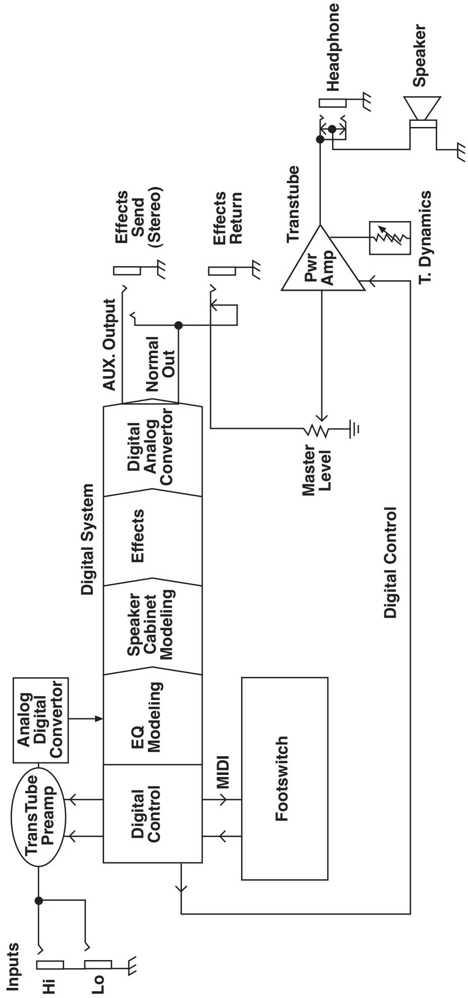
Transformer 112
Block Diagram
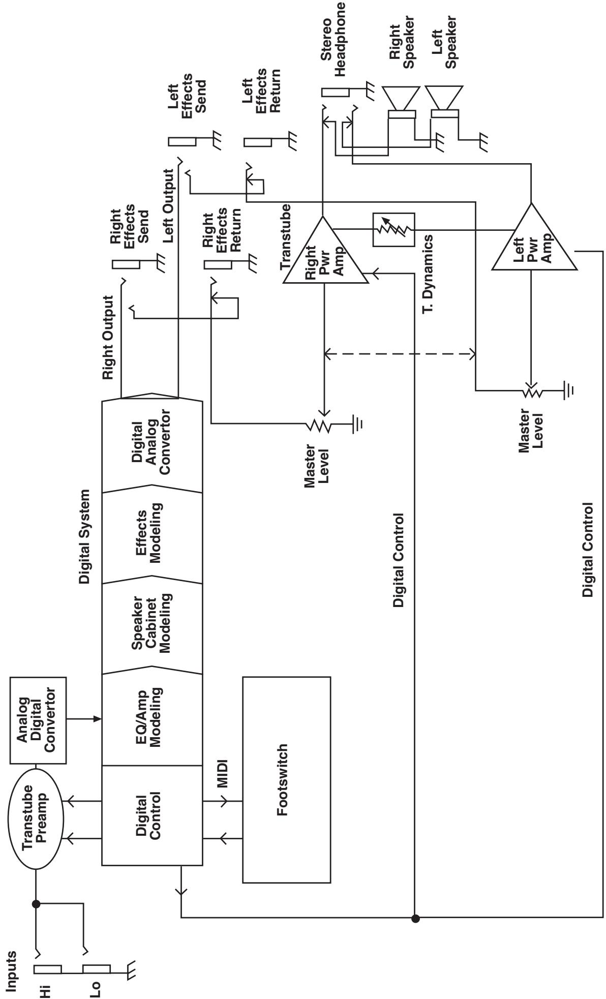
Transformer 212
Block Diagram
Transformer Specifications
POWER AMP SECTION
Rated Power and Load:
Power specs measured with T. Dynamics @ 100%
and Master Level @ 5
50 W RMS into 4 ohms (112)
2 x 50 W RMS into 4 ohms (212)
Power @ Clipping (typically):
(5% THD, 1 kHz, 120V AC line)
50 W RMS into 4 ohms (each amp)
Frequency Response:
+/-3 dB, 60 Hz to 20 kHz,
@ 30 W RMS into 4 ohms (each amp)
Power Amp Hum and Noise:
Greater than 75 dB below rated power
Power Consumption:
200 W (112) / 400 W (212) @ 50/60 Hz, 120 V AC, Domestic
200 W (112) / 400 W (212) @ 60 Hz, 220-230/240 V AC, Export
PREAMP/EFFECTS SECTION
D/A and A/D Conversion
Rate: 44.1 kHz
Quantization: 24 bit
The following specs are measured with the controls set as follows:
Master Level @ 5
T. Dynamics @ 100%
Amp model set to Classic Clean
Pre, Low, Mid, and High set to 5
Post set to 10
Reverb OFF
Modulation Depth OFF
Delay Level OFF
Noise Gate disabled
System Hum and Noise
Greater than 65 dB below rated power
Effects Send(s):
Load Impedance: 1 K ohm or greater
Nominal Output Level: -10 dBV, 0.3 V RMS
Transformer 112:
Stereo output if TRS stereo plug is used.
Tip is normal signal; ring is auxiliary signal.
Transformer 212:
Mono output, tip is positive polarity.
Effects Returns:
Impedance: High-Z, 40 K ohms
Designed Input Level: -10 dBV, 0.3 V RMS
(Switching jack provides Effects Send to
Effects Return connection when not used.)
External Footswitch Functions:
Preset/Bank Selection/Display
EFX On/Off Selection/Display
Remote Tuner Access/Display
Tap Tempo of Delay with Display
(Using PFC 4 MIDI pedal, included)
Transformer 112 Dimensions:
Width: 21 3/4 inches
Depth: 14 1/4 inches
Height: 22 3/8 inches
Weight: 39.5 lbs.
Transformer 212 Dimensions:
Width:
Depth:
Height:
Weight:
ESPAÑOL
The LED ring works like a strobe-type tuner.
When the LEDs illuminate in a counter clockwise direction, the note is flat. When the LEDs illuminate in a clockwise direction, the note is sharp.

Counter clockwise = note is flat
The faster the rotation the more out of tune.

Clockwise = note is sharp
When the LEDs illuminate to form a star shape with no rotation, the note is in tune.

No rotation (star shape) = note is tuned
NOTE: The same front panel features/functions are used for both the guitar and chromatic modes.
Pedalera
- Volumen Principal - Bx 07 nn
@ 30 W RMS a 4 ohmios
200 W @ 50/60 Hz, 120 V AC, Domestico
200 W @ 60 Hz, 220-230/240 V AC, Exportación
SECCION PREAMP/EFFECTOS
Remote Tuner Access/Display
| Amp Model | Speaker | Description |
| American | ||
| Modern | 112 | High gain, active EQ, mid control shifted to 600 Hz |
| Tweed | 410 | 50's tweed 410 combo |
| Hi Gain | 112 Chrome dome | Hot rodded American-style 112 combo |
| Clean | 212 American | 60's American-style 212 combo |
| Peavey | ||
| Ultra | 412 Peavey | High gain, active EQ, Ultra Plus, 5150 enclosure, mid shifted to 900 Hz |
| Hi Gain | 412 Peavey | 5150® enclosure, 5150/Transtube Bandit® in high gain mode |
| Classic | ||
| Clean | 112 | Peavey Classic® in clean channel |
| Crunch | 112 | Peavey Classic® in lead channel, move T.Dynamics® down for Classic 30 and up for Classic 50 |
| British | ||
| Crunch | 412 Brit. | 70's British amp with master volume |
| Vintage | 212 Brit. | 60's British amp, blues combo |
| Hi Gain | 412 Brit. | 80's Modified British with master volume |
| Clean | 212 Brit. | 60's British clean 212 combo |
9. PRE GAIN
Applications/Procedures
The LED ring works like a strobe-type tuner.
When the LEDs illuminate in a counter clockwise direction, the note is flat. When the LEDs illuminate in a clockwise direction, the note is sharp.

Counter clockwise = note is flat
The faster the rotation the more out of tune.

Clockwise = note is sharp
When the LEDs illuminate to form a star shape with no rotation, the note is in tune.

No rotation (star shape) = note is tuned
NOTE: The same front panel features/functions are used for both the guitar and chromatic modes.
Pédalier
- Bank Select - Bx 20 nn
| Address (Hex) | Name | Range (Decimal) |
| 00 | Amp Model | High nib is Cabinet Model, 0-11 *(See below.)Low nib is Preamp / Power Amp Model, 0-11Clockwise rotation for both nibs:0 = Classic Clean1 = Classic Crunch11 = British Clean |
| 01 | (controlled by model) | |
| 02 | High nib is reserved (controlled by model)Low nib is Modulation Select:0-4 = Chorus, Flanger, Phaser, Tremolo, Rotary | |
| 03,04 | Pre Gain (non-boost, boost) | 1-33 |
| 05,06 | Low (non-boost, boost) | 1-33 |
| 07,08 | Mid (non-boost, boost) | 1-33 |
| 09,0A | High (non-boost, boost) | 1-33 |
| 0B,0C | Post Gain (non-boost, boost) | 1-33 |
| 0D,0E | Reverb (primary/off, secondary/on) | 0-33 (0 = reverb off) |
| 0F | Mid Shift | 1-33 *(See below.) |
| 10 | ||
| 11,12 | Rate (primary/off, secondary/on) | 1-25 |
| 13,14 | Depth (primary/off, secondary/on) | 0-25 (0 = modulation off) |
| 15 | Flanger Feedback | 1-25 **(See below.) |
| 16 | Flanger Delay Time | 1-25 **(See below.) |
| 17 | Delay Time | 1-255 |
| 18,19 | Delay Feedback (primary/off, secondary/on) | 1-25 |
| 1A,1B | Delay Level (primary/off, secondary/on) | 0-25 (0 = delay off) |
| 1C | Delay Time Scale | 1-25 ***(See below.) |
| 1D | Delay Stereo Separation | Bit 7 is Delay Treble Rolloff (active high)Bits 6-0 are L/R delay time separation, 1-25 |
| 1E | PFC4 Tap Function | EFX Mode Status Bits | High nib controls function of TAP footswitch:0000 = Tap Tempo (default)0001 = EFX mode status reset (from preset)0010 = <reserved>0100 = <reserved>1000 = <reserved>Multiple 1's flags toggles to the corresponding bits in the low nibble. Examples:0101 = Toggles boost and delay mode1110 = Toggles all effects, but not boost etc. etc.Low nib is EFX mode status:Bit 0 is Boost (on/secondary = high)Bit 1 is Modulation (on/secondary = high)Bit 3 is Delay (on/secondary = high)Bit 4 is Reverb (on/secondary = high) |
- Values are automatically set with model selection. Write after model selection to tweak.
Values are automatically set with flanger selection. Write after flanger selection to tweak.
* Value is centered (@13, which is basically 0) after a Tap function from the amp or PFC4. Write after Tap function to tweak.
Transformer™ 112 Globals
| Offset (Hex) | Name | Range (Decimal) |
| 00 | <reserved> | Reserved (keep at zero) |
| 01 | Bank Select Method | 0 = Preset (1-4) stays the same after bank select (default) |
| 1 = Preset goes to #1 after bank select | ||
| 2 = Preset light blinks, waits for user preset selection | ||
| 02 | PFC4 All Info | 0 = Inactive mode - LED's off |
| 1 = Inactive mode - LED's dim (default) | ||
| 2 = Inactive mode - LED's bright for both modes | ||
| 03 | MIDI Channel (-1) | 0-15 for 1-16 (default = 0, channel 1) |
| 04 | Global Bits | Bit 0 set for User patches at powerup (default = 0, factory) |
| Bit 1 set for Stereo mode (default = 0, mono) | ||
| Bits 2-7 are reserved (Keep at zero.) | ||
| 05 | Noise Gate Threshold | 0=off, 1-25 (default = 5) |
| 06 | Noise Gate Sensitivity | 0-25 (default = 5) |
| 07 | <reserved> | Reserved (Keep at zero) |
| 08 | <reserved> | Reserved (Keep at zero) |
| 09 | Tuner Bits | Bit 0 set for E, mode (default = 0, standard E mode) |
| Bit 1 set for Chromatic mode (default = 0, guitar mode) | ||
| Bits 2-7 are reserved (Keep at zero.) | ||
| 0A | Tuner Volume Level | 0-25. Default is 13 (12:00). Zero is muted. |
| 0B | <reserved> | Reserved (Keep at zero.) |
| 0C | <reserved> | Reserved (Keep at zero.) |
| 0D | <reserved> | Reserved (Keep at zero.) |
Transformer 112 Specifications
POWER AMP SECTION
Rated Power and Load:
Power specs measured with T. Dynamics @ 100% and Master Level @ 5
50 W RMS into 4 ohms
Power @ Clipping (typically):
(5% THD, 1 kHz, 120V AC line)
50 W RMS into 4 ohms
Frequency Response:
+/-3 dB, 60 Hz to 20 kHz, @ 30 W RMS into 4 ohms
Power Amp Hum and Noise:
Greater than 75 dB below rated power
Power Consumption:
200 W @ 50/60 Hz, 120 V AC, Domestic
200 W @ 60 Hz, 220-230/240 V AC, Export
PREAMP/EFFECTS SECTION
D/A and A/D Conversion
Rate: 44.1 kHz
Quantization: 24 bit
The following specs are measured with the controls set as follows:
Master Level @ 5
T. Dynamics @ 100%
Amp model set to Classic Clean
Pre, Low, Mid, and High set to 5
Post set to 10
Reverb OFF
Modulation Depth OFF
Delay Level OFF
Noise Gate disabled
System Hum and Noise
Greater than 65 dB below rated power
Effects Send(s):
Load Impedance: 1 K ohm or greater
Nominal Output Level: -10 dBV, 0.3 V RMS
Stereo output if TRS stereo plug is used.
Tip is normal signal; ring is auxiliary signal.
Effects Returns:
Impedance: High-Z, 40 K ohms
Designed Input Level: -10 dBV, 0.3 V RMS (Switching jack provides Effects Send to Effects Return connection when not used.)
External Footswitch Functions:
Preset/Bank Selection/Display EFX On/Off Selection/Display Remote Tuner Access/Display Tap Tempo of Delay with Display (Using PFC 4 MIDI pedal, included)
Dimensions:
Width: 21 3/4 inches
Depth: 14 1/4 inches
Height: 22 3/8 inches
Weight 39.5 lbs.
DEUTSCH
The LED ring works like a strobe-type tuner. When the LEDs illuminate in a counter clockwise direction, the note is flat. When the LEDs illuminate in a clockwise direction, the note is sharp.

Counter clockwise = note is flat
The faster the rotation the more out of tune.
Clockwise = note is sharp
When the LEDs illuminate to form a star shape with no rotation, the note is in tune.

No rotation (star shape) = note is tuned
NOTE: The same front panel features/functions are used for both the guitar and chromatic modes.
Pedalera
@ 30 W RMS a 4 ohmios
200 W @ 50/60 Hz, 120 V AC, Domestico
200 W @ 60 Hz, 220-230/240 V AC, Exportación
SECCION PREAMP/EFECTOS
Remote Tuner Access/Display
IMPORTANT SAFETY INSTRUCTIONS
WARNING: When using electric products, basic cautions should always be followed, including the following:
- Read these instructions.
- Keep these instructions.
- Heed all warnings.
- Follow all instructions.
- Do not use this apparatus near water. For example, near or in a bathtub, swimming pool, sink, wet basement, etc.
- Clean only with a damp cloth.
- Do not block any of the ventilation openings. Install in accordance with manufacturer's instructions. It should not be placed flat against a wall or placed in a built-in enclosure that will impede the flow of cooling air.
- Do not install near any heat sources such as radiators, heat registers, stoves or other apparatus (including amplifiers) that produce heat.
- Do not defeat the safety purpose of the polarized or grounding-type plug. A polarized plug has two blades with one wider than the other. A grounding type plug has two blades and a third grounding plug. The wide blade or third prong is provided for your safety. When the provided plug does not fit into your inlet, consult an electrician for replacement of the obsolete outlet. Never break off the grounding. Write for our free booklet "Shock Hazard and Grounding". Connect only to a power supply of the type marked on the unit adjacent to the power supply cord.
- Protect the power cord from being walked on or pinched, particularly at plugs, convenience receptacles, and the point they exit from the apparatus.
- Only use attachments/accessories provided by the manufacturer.
- Use only with a cart, stand, tripod, bracket, or table specified by the manufacturer, or sold with the apparatus. When a cart is used, use caution when moving the cart/apparatus combination to avoid injury from tip-over.
- Unplug this apparatus during lightning storms or when unused for long periods of time.
- Refer all servicing to qualified service personnel. Servicing is required when the apparatus has been damaged in any way, such as power-supply cord or plug is damaged, liquid has been spilled or objects have fallen into the apparatus, the apparatus has been exposed to rain or moisture, does not operate normally, or has been dropped.
- If this product is to be mounted in an equipment rack, rear support should be provided.
- Exposure to extremely high noise levels may cause a permanent hearing loss. Individuals vary considerably in susceptibility to noise-induced hearing loss, but nearly everyone will lose some hearing if exposed to sufficiently intense noise for a sufficient time. The U.S. Government's Occupational and Health Administration (OSHA) has specified the following permissible noise level exposures:
| Duration Per Day In Hours | Sound Level dBA, Slow Response |
| 8 | 90 |
| 6 | 92 |
| 4 | 95 |
| 3 | 97 |
| 2 | 100 |
| 1 1/2 | 102 |
| 1 | 105 |
| 1/2 | 110 |
| 1/4 or less | 115 |
According to OSHA, any exposure in excess of the above permissible limits could result in some hearing loss. Ear plugs or protectors to the ear canals or over the ears must be worn when operating this amplification system in order to prevent a permanent hearing loss, if exposure is in excess of the limits as set forth above. To ensure against potentially dangerous exposure to high sound pressure levels, it is recommended that all persons exposed to equipment capable of producing high sound pressure levels such as this amplification system be protected by hearing protectors while this unit is in operation.
SAVE THESE INSTRUCTIONS!
PEAVEY ELECTRONICS CORPORATION LIMITED WARRANTY
Effective Date: July 1, 1998
What This Warranty Covers
Your Peavey Warranty covers defects in material and workmanship in Peavey products purchased and serviced in the U.S.A. and Canada.
What This Warranty Does Not Cover
The Warranty does not cover: (1) damage caused by accident, misuse, abuse, improper installation or operation, rental, product modification or neglect; (2) damage occurring during shipment; (3) damage caused by repair or service performed by persons not authorized by Peavey; (4) products on which the serial number has been altered, defaced or removed; (5) products not purchased from an Authorized Peavey Dealer.
Who This Warranty Protects
This Warranty protects only the original retail purchaser of the product.
How Long This Warranty Lasts
The Warranty begins on the date of purchase by the original retail purchaser. The duration of the Warranty is as follows:
| Product Category | Duration |
| Guitars/Basses, Amplifiers, Pre-Amplifiers, Mixers, Electronic Crossovers and Equalizers | 2 years * (+ 3 years) |
| Drums | 2 years * (+ 1 year) |
| Enclosures | 3 years * (+ 2 years) |
| Digital Effect Devices and Keyboard and MIDI Controllers | 1 year * (+ 1 year) |
| Microphones | 2 years |
| Speaker Components (incl. speakers, baskets, drivers, diaphragm replacement kits and passive crossovers) and all Accessories | 1 year |
| Tubes and Meters | 90 days |
[denotes additional warranty period applicable if optional Warranty Registration Card is completed and returned to Peavey by original retail purchaser within 90 days of purchase.]
What Peavey Will Do
We will repair or replace (at Peavey's discretion) products covered by warranty at no charge for labor or materials. If the product or component must be shipped to Peavey for warranty service, the consumer must pay initial shipping charges. If the repairs are covered by warranty, Peavey will pay the return shipping charges.
How To Get Warranty Service
(1) Take the defective item and your sales receipt or other proof of date of purchase to your Authorized Peavey Dealer or Authorized Peavey Service Center.
OR
(2) Ship the defective item, prepaid, to Peavey Electronics Corporation, International Service Center, 412 Highway 11 & 80 East, Meridian, MS 39301 or Peavey Canada Ltd., 95 Shields Court, Markham, Ontario, Canada L3R 9T5. Include a detailed description of the problem, together with a copy of your sales receipt or other proof of date of purchase as evidence of warranty coverage. Also provide a complete return address.
Limitation of Implied Warranties
ANY IMPLIED WARRANTY, INCLUDING WARRANTYES OF MERCHANTABILITY AND FITNESS FOR A PARTICULAR PURPOSE, ARE LIMITED IN DURATION TO THE LENGTH OF THIS WARRANTY.
Some states do not allow limitations on how long an implied warranty lasts, so the above limitation may not apply to you.
Exclusions of Damages
PEAVEY'S LIABILITY FOR ANY DEFECTIVE PRODUCT IS LIMITED TO THE REPAIR OR REPLACEMENT OF THE PRODUCT, AT PEAVEY'S OPTION. IF WE ELECT TO REPLACE THE PRODUCT, THE REPLACEMENT MAY BE A RECONDITIONED UNIT. PEAVEY SHALL NOT BE LIABLE FOR DAMAGES BASED ON INCONVENIENCE, LOSS OF USE, LOST PROFITS, LOST SAVINGS, DAMAGE TO ANY OTHER EQUIPMENT OR OTHER ITEMS AT THE SITE OF USE, OR ANY OTHER DAMAGES WHETHER INCIDENTAL, CONSEQUENTIAL OR OTHERWISE, EVEN IF PEAVEY HAS BEEN ADVISED OF THE POSSIBILITY OF SUCH DAMAGES.
Some states do not allow the exclusion or limitation of incidental or consequential damages, so the above limitation or exclusion may not apply to you.
This Warranty gives you specific legal rights, and you may also have other rights which vary from state to state.
If you have any questions about this warranty or service received or if you need assistance in locating an Authorized Service Center, please contact the Peavey International Service Center at (601) 483-5365 / Peavey Canada Ltd. at (905) 475-2578.
Features and specifications subject to change without notice.

PEAVY
Features and specifications subject to change without notice.
Peavey Electronics Corporation • 711 A Street • Meridian • MS • 39301 (601) 483-5365 • FAX (601) 486-1278 • www.peavey.com

80304703