USER MANUAL STUDIO PRO 112 PEAVEY
Intended to alert the user to the presence of uninsulated "dangerous voltage" within the product's enclosure that may be of sufficient magnitude to constitute a risk of electric shock to persons.

Intended to alert the user of the presence of important operating and maintenance (servicing) instructions in the literature accompanying the product.
CAUTION: Risk of electrical shock — DO NOT OPEN!
CAUTION: To reduce the risk of electric shock, do not remove cover. No user serviceable parts inside. Refer servicing to qualified service personnel.
WARNING: To prevent electrical shock or fire hazard, do not expose this appliance to rain or moisture. Before using this appliance, read the operating guide for further warnings.

Congratulations on your purchase of a Peavey TransTube® Series instrument amplifier. Whether you are a beginner or seasoned pro, you could not have found a more practical, feature-packed amplifier. Peavey's patented TransTube circuitry has moved forward into the second generation of products, leading the industry in tube emulation. There is no other solid-state amp that more closely replicates the characteristics of a tube amp.
Three TransTube Series models are described in this book due to their similarities. These models are the Envoy® 110, Studio Pro® 112 and Bandit® 112. Where applicable, the differences in the units are noted. The lists below describe the main features and differences between the amps. Please read this manual in its entirety to ensure optimum and safe operation of your new TransTube amp.
COMMON FEATURES
- High and Low Gain Inputs to accommodate a variety of instruments
-
Two distinct TransTube channels each featuring:
-
Separate Volume/Gain controls
- Low, Mid and High EQ
-
EQ/Gain voicing switches
-
Channel select switch on front panel
- Spring reverb with reverb level control
- Remote footswitch capability
ENVOY 110 FEATURES
10" Blue Marvel® speaker
- 40 watt power amplifier
- Preamp output
- Headphone jack
Footswitchable reverb and channel selection
STUDIO PRO 112 FEATURES
- 12" Blue Marvel speaker
- 65 watt power amplifier
- Effects send and return
T. Dynamics® control
- External speaker jack
Footswitchable reverb and channel selection
BANDIT 112 FEATURES
12" Sheffield® 1230 speaker
- 100 watt power amplifier (80 watts into internal speaker)
- Footswitchable effects loop and channel selection
- Effects level switch
- Preamp output
- Power amp input
- External speaker jack
T-Dynamics® control
Presence control
- Resonance switch
AC POWER
In order to apply power to your TransTube Series amp you must first identify its required AC supply voltage. The proper voltage for your unit is labeled on the upper left corner of the rear panel.
1. AC Power Cord (Under Chassis)
Locate the power cord tucked into the rear speaker compartment. This line cord provides the AC power to the unit. Connect the line cord to a properly grounded AC supply. Damage to the equipment may occur if improper line voltage is used. (See voltage marking on unit.) Never remove or cut the ground pin of the line cord plug.
NOTE: FOR UK ONLY
As the colors of the wires in the mains lead of this apparatus may not correspond with the colored markings identifying the terminals in your plug, proceed as follows: (1) The wire which is colored green and yellow must be connected to the terminal which is marked by the letter E, or by the earth symbol, or colored green or green and yellow. (2) The wire which is colored blue must be connected to the terminal which is marked with the letter N, or the color black. (3) The wire which is colored brown must be connected to the terminal which is marked with the letter L or color red.
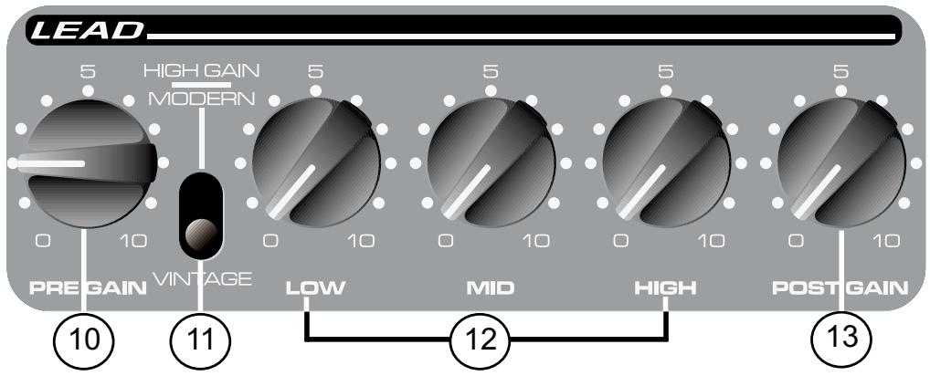
2. Power Switch (See Master Section Diagram page 7.)
Press this switch to the "ON" position to apply power. The Power LED (3) will illuminate to indicate the unit is on. Pressing the bottom portion of the switch will turn the amp off.
3. Power LED (See Master Section Diagram page 7.)
This LED will illuminate to indicate the amp is on.
TRANSTUBE PREAMP
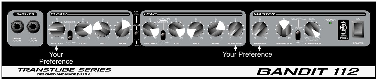
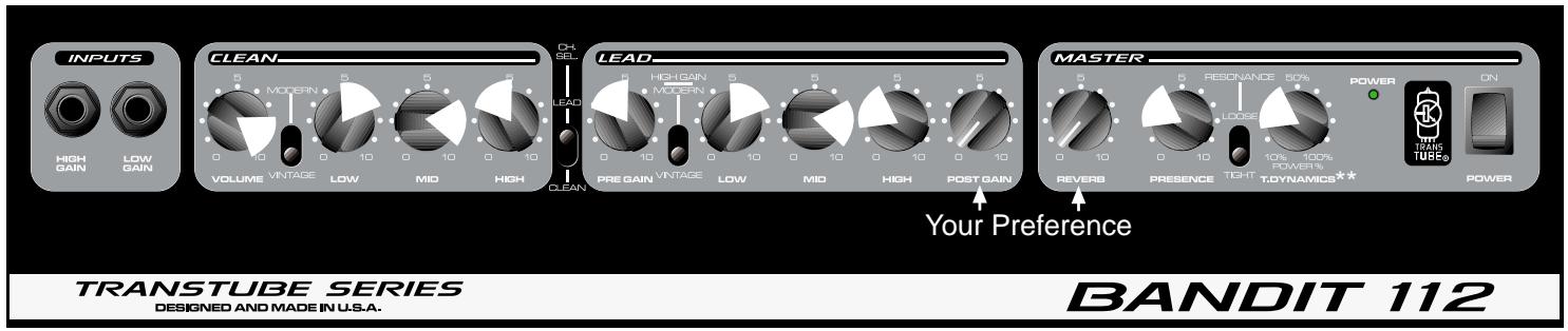
The TransTube preamp on your amplifier consists of three clearly labeled sections: Inputs, Clean (channel) and Lead (channel). Let's look at each of these areas individually.

The inputs of your TransTube Series amplifier are tailored to respond exactly like the inputs found on popular tube amplifiers. Always use quality, shielded instrument cables when connecting your instrument to the input.
This is the standard input used for most instrument applications. Most electric guitars will work ideally when plugged into this 1/4" mono input. The High Gain Input is 6 dB louder than the Low Gain Input (5).
This 1/4" mono input is provided for instruments with extremely high outputs, which can result in overdriving (distorting) the High Gain Input (4). If both the Low Gain and High Gain inputs are used simultaneously, their levels are both Low Gain.
CHANNELS
Your TransTube Series amp offers two-channel operation. Both the Clean and Lead channels provide a flexible platform for you to establish your favorite tone. The footswitch (optional on Envoy 110 and Studio Pro 112) allows remote switching between the two channels and is explained in detail on page 8 of this guide.

6. Channel Select Switch
The Channel Select Switch determines which channel of the TransTube Preamp, LEAD or CLEAN, is active. This switch must be in the "LEAD" position in order for the footswitch function of your amp to work.
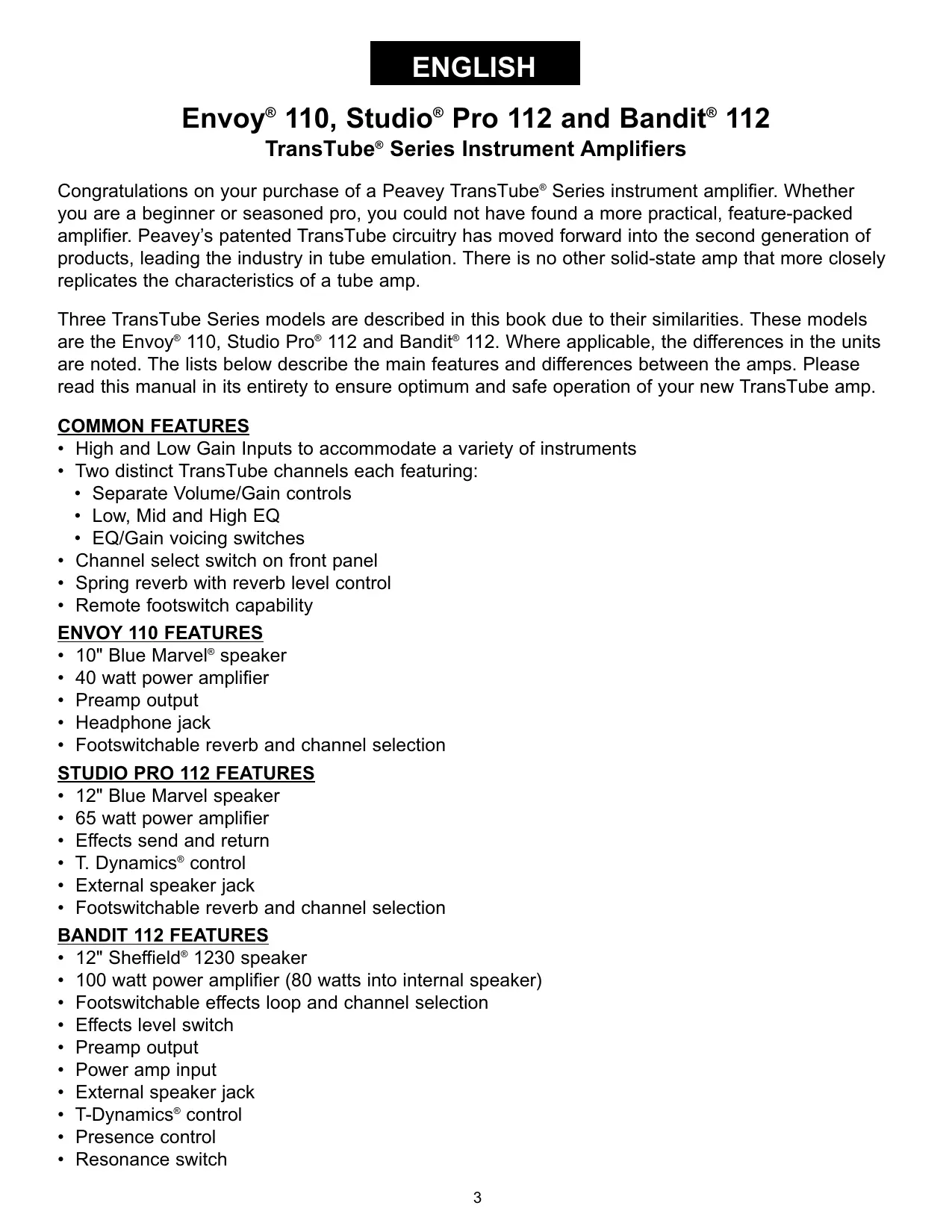
CLEAN CHANNEL
7. Volume
This control sets the volume level for the Clean channel. It is best to start with the control fully counterclockwise (minimum gain) and adjust clockwise until the desired level is achieved. After all EQ and voicing adjustments have been made to the channel, you may wish to reset this control.
8. Modern/Vintage Switch
This switch allows you to instantly change the voicing to reflect the tones of modern and vintage amplifiers. The MODERN position maintains a warm, standard voicing. The VINTAGE
position changes the overall function of the EQ and adds a hint of brightness to emulate some classic amp designs. Experiment with this switch, along with Clean EQ (9) adjustments, to capture your desired tone. You may refer to the Recommended Settings on page 11 for some creative starting points.
9. Clean EQ
The TransTube EQ featured on the Clean channel of your amp offers 3-band tone adjustment. Each EQ control is passive (does not add gain) and has a frequency range dependent on the position of the Modern/Vintage Switch. Reducing the control to the "0" position (fully counterclockwise) introduces maximum cut in level for the particular band. Low, Mid and High bands are available for adjustment.
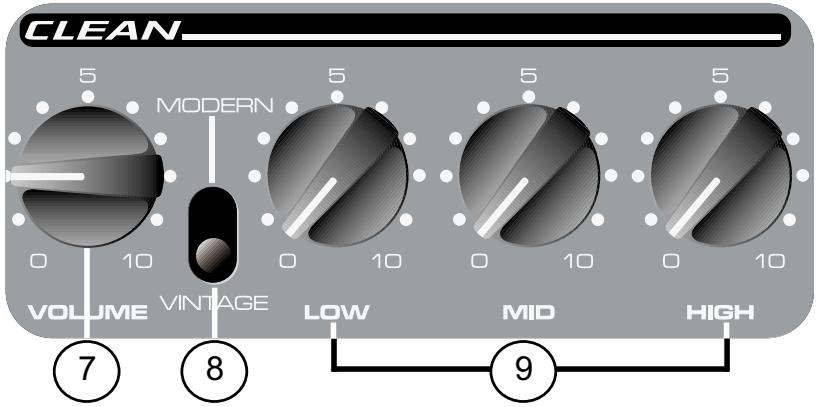
LEAD CHANNEL
10. Pre Gain
The Pre Gain control sets the input level of the Lead channel. Adjusting this control fully clockwise will result in maximum gain. This control is often used to adjust the amount of distortion present in the Lead channel.
11. Modern/Vintage/High Gain- Switch
This switch changes both the gain and voicing of the Lead channel. Selecting the MODERN setting increases the overall gain and notches (cuts) the mid frequencies to establish a modern tone often associated with Hard Rock and Metal styles. The VINTAGE position uses the TransTube circuitry to emulate overdriven tube sounds of the past. The HIGH GAIN setting increases the overall gain and changes the EQ. This creates a tighter response at lower Pre Gain settings or an "over the top" sound at higher Pre Gain settings. Experiment with this switch setting while adjusting the Lead EQ (12) to help you obtain your desired tone. You may refer to the Recommended Settings on page 11 for some creative starting points.
12. Lead EQ
The TransTube EQ featured on the Lead channel of your amp offers 3-band tone adjustment. Each EQ control is passive (does not add gain) and has a frequency range dependent on the position of the Modern/Vintage/High Gain Switch. Reducing the control to the "0" position (fully counterclockwise) introduces maximum cut in level for the particular band. Low, Mid and High bands are available for adjustment.
13. Post Gain
Use this control to set the overall level of the Lead channel once your tone has been achieved. It is best to start with the control fully counterclockwise (minimum gain) and adjust clockwise until the desired level is achieved. After all EQ and voicing adjustments have been made to the channel, you may wish to reset this control.
MASTER SECTION
The Master sections of the TransTube Series amps vary from unit to unit. Please read carefully. Each feature's description identifies its applicable model(s).
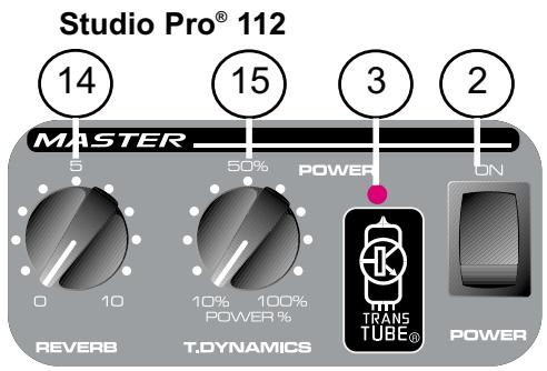
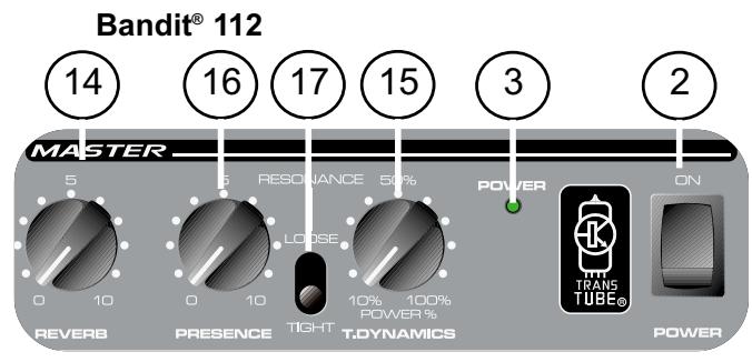
14. Reverb
The Reverb control adjusts the overall reverb level. This control is found on all three models. Note: Reverb can be defeated by the Remote Switch (18) on the Envoy 110 and Studio Pro 112 models.
15. T-Dynamics®
This control adjusts the power level of the amplifier from 10 percent to 100 percent power. When set to lower settings, the power compression simulation will be much more pronounced. This control is found on the Studio Pro 112 and Bandit 112.
16. Presence
This active tone control boosts the extreme high frequencies by as much as 6 dB. This control is found on Bandit 112 only.
17. Resonance
Use this switch to set the low frequency resonance of the speaker enclosure by varying the damping factor of the amplifier between two settings, TIGHT and LOOSE. In the TIGHT position, the amplifier has a higher damping factor causing the speaker/cabinet combination to resonate less. The LOOSE position allows the characteristics of the power amp/cabinet/speaker combination to resonate more at low frequencies. Thus, the resonant frequency of the cabinet is used to produce more low end, simulating a larger cabinet. This control is found on the Bandit 112 only.
REAR PANEL
The rear panel features of the TransTube Series amps vary from unit to unit. Please read each carefully. Each feature's description identifies its applicable model(s).
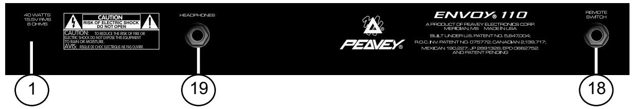

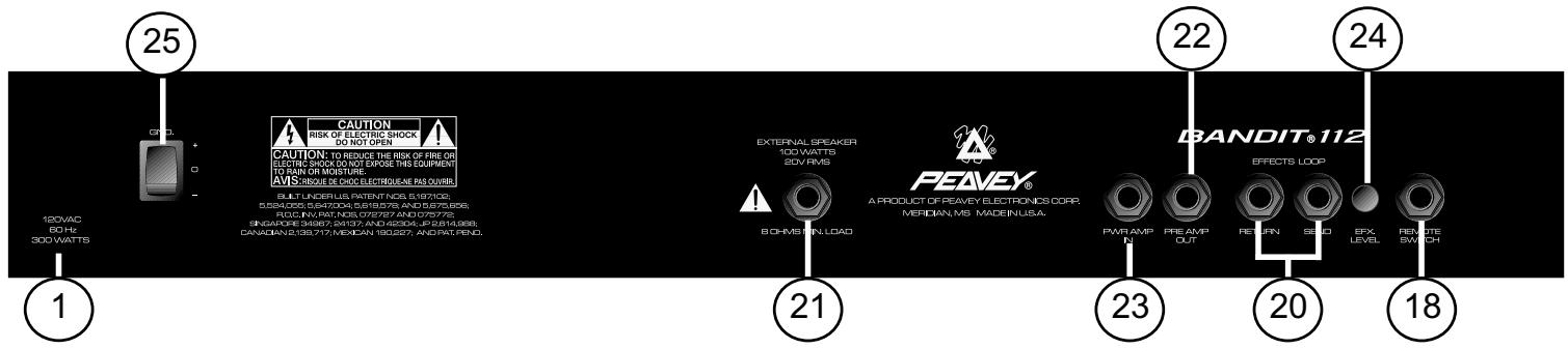
18. Remote Switch
This jack accepts the appropriate remote footswitch for your amp. The footswitch (optional on Envoy 110 and Studio Pro 112) is a multi-function type. It is used to select between the Clean and Lead channels. Additionally, the footswitch is used to activate/deactivate the Reverb on the Envoy 110 and Studio Pro 112 models. On the Bandit, the footswitch (included) provides channel selection and Effects Loop (20) defeat. The Channel Select Switch (6) must be in the LEAD position for the Remote Switch to work.
19. Headphones Jack
This stereo 1/4" jack accepts a standard pair of headphones. Using this jack defeats the output to the speaker making it ideal for quiet practice applications. This jack is featured on the Envoy 110 only.
NOTE: The remaining features apply to the Studio Pro 112 and/or the Bandit 112 models only. 20. Effects Loop
This pair of mono 1 / 4'' jacks supply an effects SEND and RETURN path for the preamp signal. Connect the SEND jack to the input of external, low-level, signal processing equipment (effects). Return the signal from your external equipment to the RETURN jack. This is known as an Effects Loop since the signal exits your amp (send) and loops (return) back to it. On the Bandit 112, the effects loop can be swapped in and out of the signal path using the supplied Remote Switch (18).
21. External Speaker Jack
This 1/4" jack is provided for the connection of an external speaker cabinet such as the Peavey 412M. The minimum external speaker impedance is 8 ohms. This jack disconnects internal speaker when used on Studio Pro 112
NOTE: The remaining features apply to the Bandit 112 model only.
22. Preamp Out
The Preamp Output can be used to route the preamp signal to a mixing console, tape recorder, etc. Using a shielded instrument cable with mono 1/4" plugs, connect the Preamp Output to the input of your outboard equipment. This patch will not affect the normal operation of your amplifier.
23. Power Amp In
Connect line level signals from external equipment to this input. Inserting a plug into this mono 1/4" jack will prevent the TransTube preamp signal from being sent to the amplifier. In this configuration, the power amp only amplifies the signal introduced at the Power Amp In jack.
24. Effects Level
This switch selects the Effects Loop (20) operating level. When the switch is pressed to the "in" position the level is set for 0 dBV (1 V RMS). Placing the switch to the "out" position changes the level to -10 dBV (0.3 V RMS). Refer to the owner's manual for your external effects to determine the correct position for this switch.
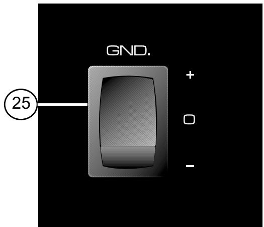
25. Ground Switch

Place this switch in the center position (0) during normal operation. If audible hum occurs, position the ground switch in either the positive (+) or negative (-) position to minimize the noise. You may have to try both positions to see which is more quiet.
NOTE: Should the noise problem continue, consult an Authorized Peavey Dealer or Peavey Repair Center. THE GROUND SWITCH IS NOT FUNCTIONAL ON 220/240 VOLT MODELS.
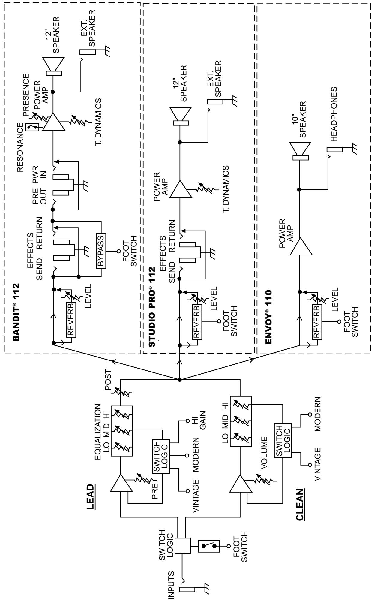
Envoy® 110, Studio® Pro 112 and Bandit® 112,
Level Diagram
RECOMMENDED SETTINGS
Clean
Metal
Jazz
Moderate Distortion
Clean Blues
Dirty Blues
NOTE: The Bandit 112 is used for demonstration purposes. The settings illustrated above are also applicable to the Envoy 110 and Studio Pro 112, with the exception of the resonance and presence controls.
ENVOY® 110
SPECIFICATIONS
POWER AMPLIFIER SECTION:
Power @ Clipping: (Typically)
(5% THD, 1 kHz, 120V AC line)
40W RMS into 6 Ohms
Frequency Response:
+0, -2 dB 100 Hz to 20 kHz @ 35W RMS
into 6 Ohms
Hum and Noise:
Greater than -86 dB below rated power
Power Consumption:
75W @ 60 Hz, 120V AC, Domestic
75W @ 50/60 Hz, 220-230/240V AC, Export
PREAMP SECTION:
The following specs are measured @ 1 kHz with the controls preset as follows:
Channel Select, Clean
Clean Mode Switch, Modern
Low and High @ 10
Mid @ 0
Lead Pre and Post Gain @ 10
Lead Mode Switch, Vintage
Reverb @ 0
Nominal Levels are with Clean Volume @ 5
Minimum Levels are with Clean Volume @ 10
Impedance: High Z, 250 K Ohms
Nominal Input Level: -13 dBV, 225mV RMS
Minimum Input Level: -22 dBV, 82mV RMS
Maximum Input Level: +0 dBV, 1V RMS
Impedance: High Z, 44k Ohms
Nominal Input Level: -7dBV, 450mV RMS
Minimum Input Level: -16dBV, 164mV RMS
Maximum Input Level: +6dBV, 2V RMS
Headphone Output:
Load Impedance: 16 Ohms or greater
Nominal Output Level: -3 dBV, 0.7V RMS
(20 Hz to 20 kHz unweighted)
Greater than 78 dB below rated power
Equalization:
Special Low, Mid, and High passive type EQ.
Modern/Vintage switch (Clean):
Two distinct EQ voicings.
Vintage/Modern/High Gain switch (Lead):
Three different EQ and Gain voicings
Select: Clean or Lead channel selection.
Reverb: Reverb bypass
Dimensions (H x W x D):
16" H x 18.13" W x 9.5" D
40.1cm x 46.1cm x 24.1cm
Weight:
21.7 lbs. (9.84 kg)
STUDIO® PRO 112 SPECIFICATIONS
POWER AMPLIFIER SECTION:
Rated Power and Load:
Power specs measured with T-Dynamics @ 100%
65W RMS into 8 Ohms
Power @ Clipping: (Typically)
(5% THD, 1 kHz, 120V AC line)
65W RMS into 8 Ohms
Frequency Response:
+3, -0 dB 100 Hz to 20 kHz @ 45W RMS into 8 Ohms
Hum and Noise:
Greater than 88 dB below rated power
Power Consumption:
200W @ 60 Hz, 120V AC, Domestic
200W @ 50/60 Hz, 220-230/240V AC, Export
PREAMP SECTION:
The following specs are measured @ 1 kHz with the controls preset as follows:
Channel Select, Clean
Clean Mode Switch, Modern
Low and High @ 10
Mid @ 0
Lead Pre and Post Gain @ 10
Lead Mode Switch, Vintage
Reverb @ 0
Nominal Levels are with Clean Volume @ 5
Minimum Levels are with Clean Volume @ 10
Impedance: High Z, 250 K Ohms
Nominal Input Level: -12 dBV, 250mV RMS
Minimum Input Level: -23 dBV, 71mV RMS
Maximum Input Level: +0 dBV, 1V RMS
Impedance: High Z, 44 k Ohms
Nominal Input Level: -6 dBV, 500mV RMS
Minimum Input Level: -17dBV, 142mV RMS
Maximum Input Level: +6 dBV, 2V RMS
Effects Send:
Load Impedance: 1k Ohms or greater
Nominal Output Level:
Effects Level -9dBV, 355 mV RMS
Effects Return:
Impedance: High Z, 22k Ohms
Designed Input Level:
Effects Level -9dBV, 355 mV RMS
(Switching jack provides Effects Send to Effects
Return connection when not used.)
(20Hz to 20kHz unweighted)
Greater than 74dB below rated power
Equalization:
Special Low, Mid, and High passive type EQ
Modern/Vintage switch (Clean): Two distinct EQ voicings
Vintage/Modern/High Gain switch (Lead):
Three different EQ and Gain voicings
Select: Clean or Lead channel selection
Reverb: Reverb bypass
Dimensions (H x W x D):
18" x 21.5" x 10.5"
Rated Power and Load:
Power specs measured with T-Dynamics @ 100%
80W RMS into 8 Ohms
100W RMS into 4 Ohms
Power @ Clipping: (Typically)
(5% THD, 1 kHz, 120V AC line)
80W RMS into 8 Ohms
100W RMS into 4 Ohms
Frequency Response:
+0, -3 dB 100 Hz to 20 kHz @ 65W RMS
into 8 Ohms
Hum and Noise:
Greater than 88 dB below rated power
Power Consumption:
300W @ 60 Hz, 120V AC, Domestic
300W @ 50/60 Hz, 220-230/240V AC, Export
PREAMP SECTION:
The following specs are measured @ 1 kHz with the controls preset as follows:
Channel Select, Clean
Clean Mode Switch, Modern
Low and High @ 10
Mid @ 0
Lead Pre and Post Gain @ 10
Lead Mode Switch, Vintage
Reverb @ 0
Nominal Levels are with Clean Volume @ 5
Minimum Levels are with Clean Volume @ 10
Preamp High Gain Input:
Impedance: High Z, 250 K Ohms
Nominal Input Level: -14 dBV, 185mV RMS
Minimum Input Level: -23 dBV, 66mV RMS
Maximum Input Level: +0 dBV, 1V RMS
Preamp Low Gain Input:
Impedance: High Z, 44 k Ohms
Nominal Input Level: -8 dBV, 380 mV RMS
Minimum Input Level: -17 dBV, 136 mV RMS
Maximum Input Level: +6 dBV, 2 V RMS
Effects Send:
Load Impedance: 1 k Ohms or greater
Nominal Output Level:
Effects Level switch "out": -10 dBV,
0.32V RMS
Effects Level switch "in": 0 dBV, 1V RMS
Effects Return:
Impedance: High Z, 22k Ohms
Designed Input Level:
Effects Level switch "out": -10 dBV,
0.32V RMS
Effects Level switch "in": 0dBV, 1V RMS
(Switching jack provides Effects Send to Effects
Return connection when not used.)
Preamp Output:
Load Impedance: 1 k Ohms or greater
Nominal Output Level: 0 dBV, 1V RMS
Power Amp Input:
Impedance: High Z, 22k Ohms
Designed Input Level: 0 dBV, 1V RMS
(Switching jack provides preamp output to power
amp input connection when not used.)
System Hum and Noise @ Nominal Input Level:
(20 Hz to 20 kHz unweighted)
Greater than 78 dB below rated power
Equalization:
Special Low, Mid, and High passive type EQ
Modern/Vintage switch (Clean): Two distinct EQ voicings
Vintage/Modern/High Gain switch (Lead):
Three different EQ and Gain voicings
Presence: +6 dB @ 5 kHz
Push Resonance: +6 dB @ resonant
frequency of cabinet
External Footswitch Functions:
Select: Clean or Lead channel selection
Effects: Effects loop bypass
Dimensions (H x W x D):
19.75" x 23.63" x 11.5"
50.16cm x 60.02cm x 29.2cm
Weight:
43.9lbs. (19.91kg)
Specifications subject to change without notice.
ESPAÑOL
CANAL LIMPIO (CLEAN)
7. Volumen
(5% THD, 1 kHz, 120V linea CA)
40W RMS a 6 Ohmios
Pre and Post Ganancia Lider @ 10
Switch Modo Líder, 'Vintage'
Reverb @ 0
Niveles Nominal son con Volumen Limpio @ 5
16'' × 18.13'' × 9.5''
40.1cm x 46.1cm x 24.1cm
Peso:
21.7 lbs. (9.84 kg)
STUDIO® PRO 112 ESPECIFICACIONES
SECCION DEL AMPLIFICADOR DE PODER:
(5% THD, 1 kHz, 120V CA linea)
65W a 8 Ohmios
18'' × 21.5'' × 10.5''
Switchnh Modo Lider, 'Vintage'
Reverb @ 0
Niveles Nominal son con Volumen Limpio @ 5
Niveles MInimum son con Volumen Limpio @ 10
50.16cm x 60.02cm x 29.2cm
Peso:
43.9lbs. (19.91kg)
FRANÇAIS
Impédance: High Z, 250 K Ohms
Impédance: High Z, 44k Ohms
Selection: Selection canal Clean ou Lead.
Reverb: Derivation de reverb
Dimensions (H x L x P):
16"Hx18,13"Wx9,5" D
40,1cm x 46,1cm x 24,1cm
Poids:
21,7 lbs. (9,84 kg)
STUDIO PRO 112 SPECIFICATIONS
SECTION AMPLIFICATEUR DE PUISSANCE:
Impedance: High Z, 250 K Ohms
Nominal Input Level (Niveau d'entree nominal): -12 dBV, 250mV RMS
Minimum Input Level (Niveau d'entrée minimal): -23 dBV, 71mV RMS
Impédance: High Z, 44 k Ohms
Effects Send (Envoi effects):
Impedance: High Z, 22k Ohms
Reverb: Derivation de reverb
Dimensions (H x L x P):
18'' × 21,5'' × 10,5''
Impedance: High Z, 250 K Ohms
Nominal Input Level (Niveau d'entree nominal): -14 dBV, 185mV RMS
Minimum Input Level (Niveau d'entrée minimal): -23 dBV, 66mV RMS
Impédance: High Z, 44 k Ohms
Nominal Input Level (Niveau d'entrée nominal): -8 dBV, 380mV RMS
Minimum Input Level (Niveau d'entrée minimal): -17 dBV, 136 mV RMS
Effects Send (Envoi effects):
Impedance: High Z, 22k Ohms
Impédance: High Z, 22k Ohms
Dimensions (H x L x P):
19,75" x 23,63" x 11,5"
Power @ Clipping: (Standard)
(5% THD, 1 kHz, 120V AC-Line)
40W RMS in 6 Ohm
Frequency Response:
Reverb: Reverb Bypass
Maße (H x B x T):
16"H x 18,13"B B x 9,5" T
40,1cm x 46,1cm x 24,1cm
Gewicht:
21,7 lbs, (9,84 kg)
STUDIO® PRO 112 SPEZifikATIONEN
VERSTÄRKER-TEIL:
Power @ Clipping: (Standard)
(5% THD, 1 kHz, 120V AC-Line)
65W RMS in 8 Ohm
Frequency Response:
Impedanz: High Z, 250 K Ohm
Nominaler Input-Level: -12 dBV, 250mV RMS
Minimum-Input-Level: -23 dBV, 71mV RMS
Maximum-Input-Level: +0 dBV, 1V RMS
Impedanz: High Z, 44 k Ohm
Nominaler Input-Level: -6 dBV, 500mV RMS
Minimum-Input-Level: -17dBV, 142mVRMS
Maximum-Input-Level: +6 dBV, 2V RMS
Effects Send:
Designed Input-Level:
Effects Level -9dBV, 355 mV RMS
Reverb: Reverb Bypass
Maße (H x B x T):
18'' × 21,5'' × 10,5''
Power @ Clipping: (Standard)
(5% THD, 1 kHz, 120V AC-Line)
80W RMS in 8 Ohm
100W RMS in 4 Ohm
Frequency Response:
Designed Input-Level:
Effects Level-Schalter "out": -10 dBV, 0,32V RMS
Effects Level-Schalter "in": 0dBV, 1V RMS
Designed Input-Level: 0 dBV, 1V RMS
Presence: +6 dB @ 5 kHz
Push Resonance: +6 dB @
Effects: Effects-Loop Bypass
Maße (H x B x T):
19,75" x 23,63" x 11,5"
IMPORTANT SAFETY INSTRUCTIONS
WARNING: When using electric products, basic cautions should always be followed, including the following:
- Read these instructions.
- Keep these instructions.
- Heed all warnings.
- Follow all instructions.
- Do not use this apparatus near water. For example, near or in a bathtub, swimming pool, sink, wet basement, etc.
- Clean only with a damp cloth.
- Do not block any of the ventilation openings. Install in accordance with manufacturer's instructions. It should not be placed flat against a wall or placed in a built-in enclosure that will impede the flow of cooling air.
- Do not install near any heat sources such as radiators, heat registers, stoves or other apparatus (including amplifiers) that produce heat.
- Do not defeat the safety purpose of the polarized or grounding-type plug. A polarized plug has two blades with one wider than the other. A grounding type plug has two blades and a third grounding plug. The wide blade or third prong is provided for your safety. When the provided plug does not fit into your inlet, consult an electrician for replacement of the obsolete outlet. Never break off the grounding. Write for our free booklet "Shock Hazard and Grounding". Connect only to a power supply of the type marked on the unit adjacent to the power supply cord.
- Protect the power cord from being walked on or pinched, particularly at plugs, convenience receptacles, and the point they exit from the apparatus.
- Only use attachments/accessories provided by the manufacturer.
- Use only with a cart, stand, tripod, bracket, or table specified by the manufacturer, or sold with the apparatus. When a cart is used, use caution when moving the cart/apparatus combination to avoid injury from tip-over.
- Unplug this apparatus during lightning storms or when unused for long periods of time.
- Refer all servicing to qualified service personnel. Servicing is required when the apparatus has been damaged in any way, such as power-supply cord or plug is damaged, liquid has been spilled or objects have fallen into the apparatus, the apparatus has been exposed to rain or moisture, does not operate normally, or has been dropped.
- If this product is to be mounted in an equipment rack, rear support should be provided.
- Exposure to extremely high noise levels may cause a permanent hearing loss. Individuals vary considerably in susceptibility to noise-induced hearing loss, but nearly everyone will lose some hearing if exposed to sufficiently intense noise for a sufficient time. The U.S. Government's Occupational and Health Administration (OSHA) has specified the following permissible noise level exposures:
| Duration Per Day In Hours | Sound Level dBA, Slow Response |
| 8 | 90 |
| 6 | 92 |
| 4 | 95 |
| 3 | 97 |
| 2 | 100 |
| 1 1/2 | 102 |
| 1 | 105 |
| 1/2 | 110 |
| 1/4 or less | 115 |
According to OSHA, any exposure in excess of the above permissible limits could result in some hearing loss. Ear plugs or protectors to the ear canals or over the ears must be worn when operating this amplification system in order to prevent a permanent hearing loss, if exposure is in excess of the limits as set forth above. To ensure against potentially dangerous exposure to high sound pressure levels, it is recommended that all persons exposed to equipment capable of producing high sound pressure levels such as this amplification system be protected by hearing protectors while this unit is in operation.
SAVE THESE INSTRUCTIONS!
PEAVEY ELECTRONICS CORPORATION LIMITED WARRANTY
Effective Date: July 1, 1998
What This Warranty Covers
Your Peavey Warranty covers defects in material and workmanship in Peavey products purchased and serviced in the U.S.A. and Canada.
What This Warranty Does Not Cover
The Warranty does not cover: (1) damage caused by accident, misuse, abuse, improper installation or operation, rental, product modification or neglect; (2) damage occurring during shipment; (3) damage caused by repair or service performed by persons not authorized by Peavey; (4) products on which the serial number has been altered, defaced or removed; (5) products not purchased from an Authorized Peavey Dealer.
Who This Warranty Protects
This Warranty protects only the original retail purchaser of the product.
How Long This Warranty Lasts
The Warranty begins on the date of purchase by the original retail purchaser. The duration of the Warranty is as follows:
| Product Category | Duration |
| Guitars/Basses, Amplifiers, Pre-Amplifiers, Mixers, Electronic Crossovers and Equalizers | 2 years *(+ 3 years) |
| Drums | 2 years *(+ 1 year) |
| Enclosures | 3 years *(+ 2 years) |
| Digital Effect Devices and Keyboard and MIDI Controllers | 1 year *(+ 1 year) |
| Microphones | 2 years |
| Speaker Components (incl. speakers, baskets, drivers, diaphragm replacement kits and passive crossovers) and all Accessories | 1 year |
| Tubes and Meters | 90 days |
[denotes additional warranty period applicable if optional Warranty Registration Card is completed and returned to Peavey by original retail purchaser within 90 days of purchase.]
What Peavey Will Do
We will repair or replace (at Peavey's discretion) products covered by warranty at no charge for labor or materials. If the product or component must be shipped to Peavey for warranty service, the consumer must pay initial shipping charges. If the repairs are covered by warranty, Peavey will pay the return shipping charges.
How To Get Warranty Service
(1) Take the defective item and your sales receipt or other proof of date of purchase to your Authorized Peavey Dealer or Authorized Peavey Service Center.
OR
(2) Ship the defective item, prepaid, to Peavey Electronics Corporation, International Service Center, 412 Highway 11 & 80 East, Meridian, MS 39301 or Peavey Canada Ltd., 95 Shields Court, Markham, Ontario, Canada L3R 9T5. Include a detailed description of the problem, together with a copy of your sales receipt or other proof of date of purchase as evidence of warranty coverage. Also provide a complete return address.
Limitation of Implied Warranties
ANY IMPLIED WARRANTY, INCLUDING WARRANTY OF MERCHANTABILITY AND FITNESS FOR A PARTICULAR PURPOSE, ARE LIMITED IN DURATION TO THE LENGTH OF THIS WARRANTY.
Some states do not allow limitations on how long an implied warranty lasts, so the above limitation may not apply to you.
Exclusions of Damages
PEAVEY'S LIABILITY FOR ANY DEFECTIVE PRODUCT IS LIMITED TO THE REPAIR OR REPLACEMENT OF THE PRODUCT, AT PEAVEY'S OPTION. IF WE ELECT TO REPLACE THE PRODUCT, THE REPLACEMENT MAY BE A RECONDITIONED UNIT. PEAVEY SHALL NOT BE LIABLE FOR DAMAGES BASED ON INCONVENIENCE, LOSS OF USE, LOST PROFITS, LOST SAVINGS, DAMAGE TO ANY OTHER EQUIPMENT OR OTHER ITEMS AT THE SITE OF USE, OR ANY OTHER DAMAGES WHETHER INCIDENTAL, CONSEQUENTIAL OR OTHERWISE, EVEN IF PEAVEY HAS BEEN ADVISED OF THE POSSIBILITY OF SUCH DAMAGES. Some states do not allow the exclusion or limitation of incidental or consequential damages, so the above limitation or exclusion may not apply to you.
This Warranty gives you specific legal rights, and you may also have other rights which vary from state to state.
If you have any questions about this warranty or service received or if you need assistance in locating an Authorized Service Center, please contact the Peavey International Service Center at (601) 483-5365 / Peavey Canada Ltd. at (905) 475-2578.
Features and specifications subject to change without notice.

PEAVY
Features and specifications subject to change without notice.
Peavey Electronics Corporation • 711 A Street • Meridian • MS • 39301
(601) 483-5365 • FAX (601) 486-1278 • www.peavey.com

80304681