
MES3500-24F - Network switch ZYXEL - Free user manual and instructions
Find the device manual for free MES3500-24F ZYXEL in PDF.
| Product Type | Manageable network switch |
| Brand | Zyxel |
| Model | MES3500-24F |
| Number of ports | 24 Fast Ethernet ports (10/100 Mbps) |
| Uplink ports | 2 Gigabit Ethernet ports (10/100/1000 Mbps) or SFP slots |
| Cable type | UTP/STP Category 5 for 100/1000 Mbps |
| Auto-negotiation | Yes, on all RJ-45 ports |
| Auto-crossover (Auto MDI/MDI-X) | Yes |
| Indicator LEDs | PWR (power), LNK/ACT (link/activity) per port |
| Management | Via RS-232 console (console port) |
| Installation | On desktop or in rack (mounting kit included) |
| Dimensions (W x D x H) | Approximately 440 x 200 x 44 mm (1U) |
| Weight | Approximately 2.8 kg |
| Power supply | External power adapter 100-240 V AC, 50/60 Hz |
| Power consumption | Max 30 W |
| Ventilation | Internal fans; leave 10 cm clearance in front, 8 cm at rear |
| Operating temperature | 0 °C to 40 °C |
| Operating humidity | 10% to 90% without condensation |
| Maintenance and cleaning | Disconnect power before cleaning; use a dry, soft cloth |
| Safety | Follow ventilation instructions; do not block vents |
| Spare parts and repairability | Contact your Zyxel dealer for any hardware issues |
| General information | Switch from the Dimension series; manual downloadable in PDF |
Frequently Asked Questions - MES3500-24F ZYXEL
User questions about MES3500-24F ZYXEL
0 question about this device. Answer the ones you know or ask your own.
Ask a new question about this device
Download the instructions for your Network switch in PDF format for free! Find your manual MES3500-24F - ZYXEL and take your electronic device back in hand. On this page are published all the documents necessary for the use of your device. MES3500-24F by ZYXEL.
USER MANUAL MES3500-24F ZYXEL
This Quick Start Guide is for use with all ZyXEL Ethernet switches. Your device may differ from the illustrations below.
2 Installation
All switches can be used as a standalone device while some can alternatively be mounted on standard EIA racks.
Note: For proper ventilation, allow at least 4 inches (10 cm) of clearance at the front and 3.4 inches (8 cm) at the back of the switch. Leave space between switches if stacking.
2.1 Desktop Installation
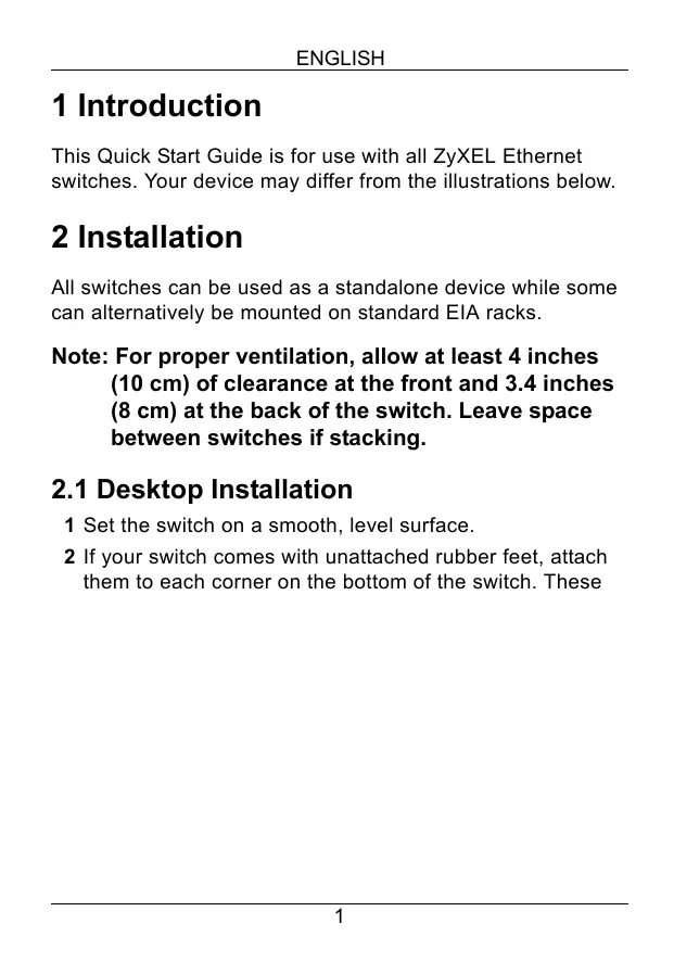
1 Set the switch on a smooth, level surface.
2 If your switch comes with unattached rubber feet, attach them to each corner on the bottom of the switch. These
rubber feet help protect the switch from shock or vibration and ensure space between devices when stacking.
natural_image
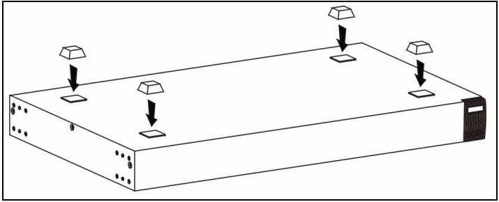
Diagram of a server rack with four square units and three downward-pointing arrows indicating force or movement (no text or symbols)2.2 Rack-mounted Installation
1 Align one bracket with the holes on one side of the switch and secure it with bracket screws smaller than the rack-mounting screws. Similarly, attach the other bracket.
natural_image
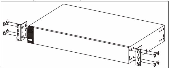
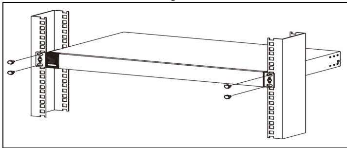
Technical line drawing of a rectangular electronic device with two connectors and mounting holes (no text or symbols)2 After attaching both mounting brackets, position the switch in the rack by lining up the holes in the brackets with the
appropriate holes on the rack. Secure the switch to the rack with the rack-mounting screws.
natural_image
Technical line drawing of a structural assembly with beams and supports (no text or symbols)3 Hardware Connections
3.1 Auto-negotiating and Auto-crossover RJ-45 ports
Your switch comes with auto-negotiating, auto-crossover ports. Depending on the model, these ports are either fast Ethernet (10/100 Mbps) or Gigabit (10/100/1000 Mbps) ports. Auto-negotiating ports can detect the speed of incoming transmissions and allow either half duplex transfer mode (10/100 Mbps only) or full duplex mode. Auto-crossover means that you can connect the switch to a computer or hub using either a straight-through or a crossover Ethernet cable.
3.2 Network Cables
You can use unshielded twisted pair (UTP) or shielded twisted-pair (STP) Ethernet cables for RJ-45 ports. Make sure the cable length between connections does not exceed 100 meters (328 feet). The following table describes the types of network cable used for different connection speeds.
Table 1 Network Cable Types
| SPEED | NETWORK CABLE TYPE |
| 10Mbps | 100 Ω 2-pair UTP/STP Category 3,4 or 5 |
| 100Mbps | 100 Ω 2-pair UTP/STP Category 5 |
| 1000Mbps | 100 Ω 4-pair UTP/STP Category 5 |
The LNK/ACT LED should flash when data is being sent between your switch and a connected device.
3.3 Power Connection
Connect one end of the supplied power cable or power adaptor to the power receptacle on the switch and the other end to the appropriate power source. The PWR LED should turn steady on if the switch is receiving power.
3.4 Console Port (Managed Switches Only)
If your switch has a console port, you can use a terminal emulator for local management. Connect the male 9-pin end of a console cable to the console port of the switch. Connect the female end to a serial port (COM1, COM2 or other COM port) of your computer. Configure the computer with terminal emulation software to the following parameters:
• VT100 terminal emulation
- 9600 bps
- No parity, 8 data bits, 1 stop bit
- No flow control
4 Troubleshooting
| PROBLEM | CORRECTIVE ACTION |
| None of the LEDs are on when the power is connected. | Verify that the included power or cable adaptor is connected to the switch's power receptacle and appropriate power source. If the error persists, you may have a hardware problem and should contact your vendor. |
| The LNK/ACT LED does not light up or flash when a device is connected. | Verify that the attached device(s) is turned on and properly connected to your switch. Also make sure the Ethernet cards are working on the attached devices. Verify that the network cable does not exceed 100 meters. |
1 Einleitung
natural_image
Isometric diagram of a rectangular device with four square components and three upward-pointing arrows, no text or symbols present.2.2 Rack-Montage
natural_image
Technical line drawing of a rectangular electronic device with two connectors and ports, no text or symbols presentnatural_image
Technical line drawing of a structural beam assembly with mounting flanges and support beams (no text or symbols)3 Hardware-Anschlüsse
natural_image
Isometric diagram of a rectangular device with four square components and three upward-pointing arrows, no text or symbols present.natural_image
Technical line drawing of a rectangular electronic device with two ports and connectors, no text or symbols present.natural_image
Technical line drawing of a structural beam assembly with mounting flanges and support beams (no text or symbols)natural_image
Diagram of a server rack with four square units and three hanging square units on top (no text or symbols)natural_image
Technical line drawing of a rectangular electronic device with mounting connectors and internal components (no text or symbols)natural_image
Technical line drawing of a structural beam assembly with mounting flanges and support beams (no text or symbols)3.4 Port Console (Switches Manageables Uniquement)
natural_image
Diagram of a server rack with four square components and three hanging square units (no text or symbols)natural_image
Technical line drawing of a server rack with two connectors and terminal blocks (no text or symbols)natural_image
Technical line drawing of a structural beam assembly with mounting flanges and support beams (no text or symbols)natural_image
Diagram of a server rack with four square components and three hanging square units (no text or symbols)natural_image
Technical line drawing of a rectangular electronic device with multiple ports and connectors (no text or symbols)natural_image
Technical line drawing of a structural beam assembly with mounting flanges and support beams (no text or symbols)natural_image
Isometric diagram of a server rack with four square buttons and three diamond-shaped indicators (no text or symbols)2.2 安裝於標準機架上
natural_image
Technical line drawing of a rectangular electronic device with mounting connectors and ports (no text or symbols)natural_image
Technical line drawing of a mechanical assembly with two vertical plates and a central rectangular component (no text or symbols)3 硬體連接
- Installation
- Desktop Installation
- Rack-mounted Installation
- Hardware Connections
- Auto-negotiating and Auto-crossover RJ-45 ports
- Network Cables
- Power Connection
- Console Port (Managed Switches Only)
- Einleitung
- Rack-Montage
- Hardware-Anschlüsse
- Port Console (Switches Manageables Uniquement)
- 安裝於標準機架上
- 硬體連接
Brand : ZYXEL
Model : MES3500-24F
Category : Network switch