
UNI_RA_01 - Washing machine Uniprodo - Free user manual and instructions
Find the device manual for free UNI_RA_01 Uniprodo in PDF.


| Product type | Manual balcony awning (canopy) |
| Brand | Uniprodo |
| Model | UNI_RA_01 / UNI_RA_02 |
| Usage | Protection against sun and light rain on balcony or terrace |
| Available width | 2.0 m, 2.5 m, or 3.0 m (depending on model) |
| Main structure | Torsion bars, arms, front bar, and roller |
| Fabric | Fabric with valance and lining cords |
| Installation | Wall mounting with brackets and expansion bolts |
| Number of installers | Recommended: 2 people |
| Tilt angle | Approximately 80° between the awning surface and the wall |
| Adjustment | Jack screws and lock nuts to adjust the horizontal level |
| Safety | Safety sleeves on the arms to be removed only after assembly |
| Maintenance | Clean with a soft cloth and soapy water |
| Spare parts | Front bars, torsion bars, arms, fabric, connectors, wall brackets, and screws |
| Power supply | None (manual operation) |
| Estimated weight | Approximately 30 kg |
| Materials | Aluminum, steel, and waterproof fabric |
Frequently Asked Questions - UNI_RA_01 Uniprodo
User questions about UNI_RA_01 Uniprodo
0 question about this device. Answer the ones you know or ask your own.
Ask a new question about this device
Download the instructions for your Washing machine in PDF format for free! Find your manual UNI_RA_01 - Uniprodo and take your electronic device back in hand. On this page are published all the documents necessary for the use of your device. UNI_RA_01 by Uniprodo.
USER MANUAL UNI_RA_01 Uniprodo
A: A-Roller
B: B-Roller
G: Stecker
G-3: Bolzen
Demonstration

4. Verbindungsarme
1: Einfügen in
2: Straff
3: Straff
Demonstration
1
2
3
4
Anmerkung:
1- Seitenansicht

ACHTUNG!
(B-Roller; B-Frontbar; B-Torsionsstange; B-Arm)
x1 Handkurbel (E)
6.

(F-1)
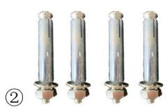
(F-2)
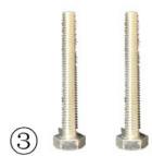
(F-3)
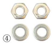
(F-4)
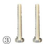
F-3: x2 Schraube M8x60
(H-1)
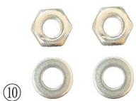
(H-2)
④
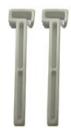
(H-3)
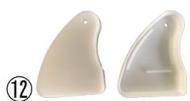
(H-4)
This User Manual has been translated for your convenience using machine translation. Reasonable efforts have been made to provide an accurate translation; however, no automated translation is perfect nor is it intended to replace human translators. The official User Manual is the English version. Any discrepancies or differences created in the translation are not binding and have no legal effect for compliance or enforcement purposes. If any questions arise related to the accuracy of the information contained in the User Manual, please refer to the English version of those contents which is the official version.
Technical data
| Parameter description | Parameter value | |
| Product name | Manual balcony awning | |
| Model | UNI_RA_01 | UNI_RA_02 |
Purpose
Manual balcony awning is used to provide shade and protection from the sun and light rain on a balcony or patio area.
Installation
ASSEMBLY
1. Connecting Roller Tubes
Insert roller connector (G) into right roller (B-Roller), fasten it with bolt (g-3). Link the left roller (A-Roller) to the connector (G), fasten it with bolt (G-3). Now you have a full length roller.
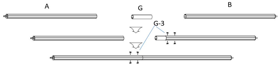
A: A-Roller
B: B-Roller
G: Connector
G-3: Bolt
Demonstration

2. Connecting Torsion Bars
Torsion bar assembly: Insert torsion bar connector (F) into right torsion bar (B-2), fasten with bolt (B-B-1). Link left torsion bar (B-1) with connector (B-3), fasten with bolt (B-B-1). Now you have a full length torsion bar.
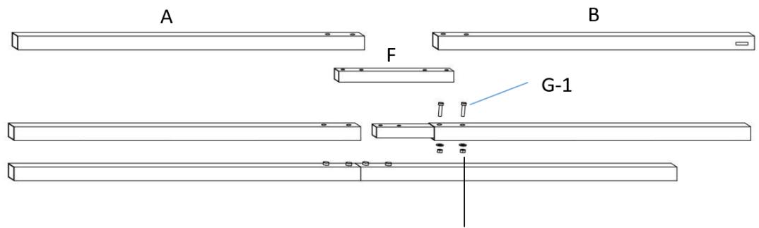
G-2
A: A-Torsion Bar
B: B-Torsion Bar
F: Connector
Demonstration

3. Connecting Front Bars
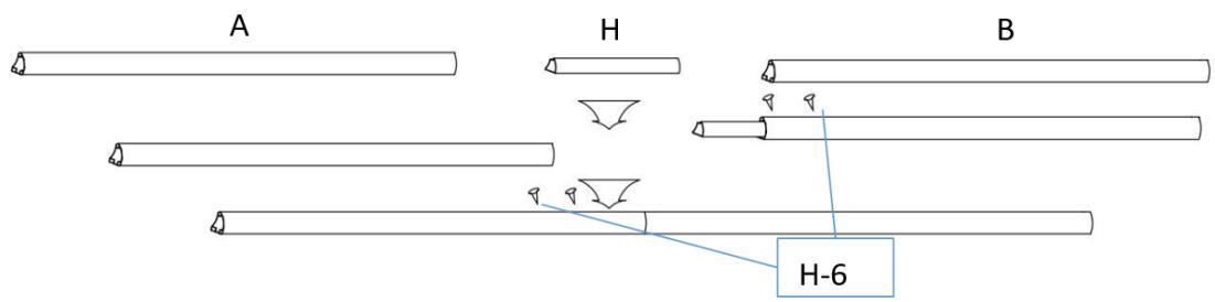
Front bar assembly: Insert front bar connector (H) into right front bar (B-Front Bar), fasten with bolt (H-6). Link left front bar (A-Front Bar) with the connector (H), fasten it with bolt (H-6). Now you have a full length front bar.
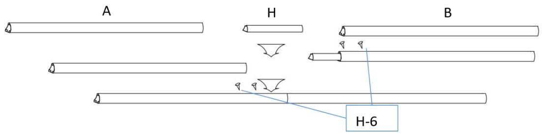
A: A-Front Bar
B: B-Front Bar
H: Connector
H-6: Bolt
Demonstration

4. Connecting Arms
The left arm(A-Arm) and right arm(B-Arm) already assembly in the Torsion bar. (This step is already done by factory)

WARNING!
- Arms should be tied together during installation to avoid bouncing out and cause injury in this step.
- Do not remove the safety sleeves that hold the arms down!

A: A-Arm
B: B-Arm
5. Fabric Assembly
1) Open the box carefully to ensure that the fabric and valance are not damaged.
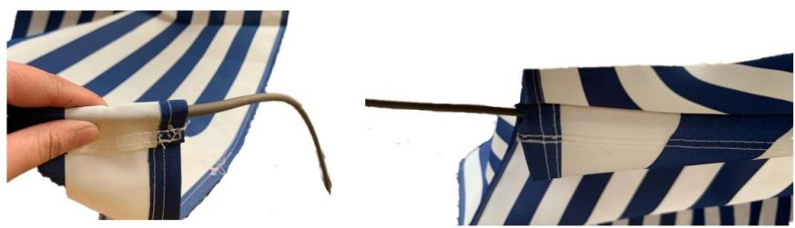
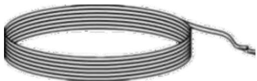
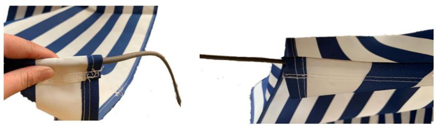
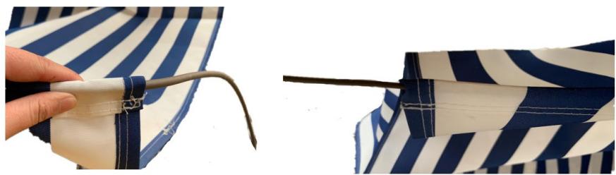
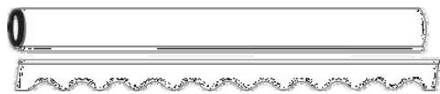
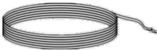
2) Unfold the pieces of awning fabric. You should have one large fabric piece (C) and a valance with a scalloped edge. You should also have three fabric liner cords, two thick and one thinner (D).
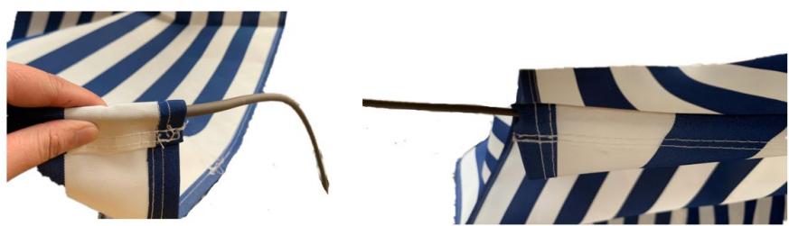
3) Thread the fabric liner, one thick and one thin, through both ends of the large awning fabric (C). This may be a slow process and is easiest with two people.

C: Fabric
D: Fabric liner cords
Demonstration
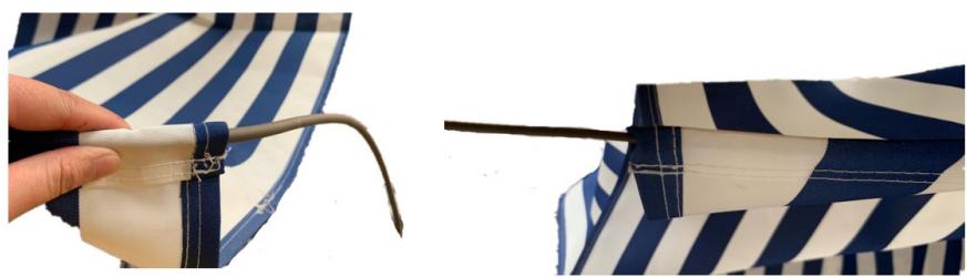
Insert the thick liner and thin liner into both ends of large fabric piece.
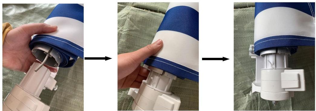
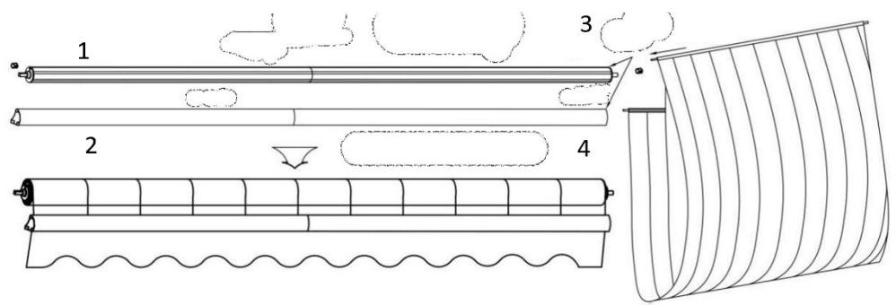
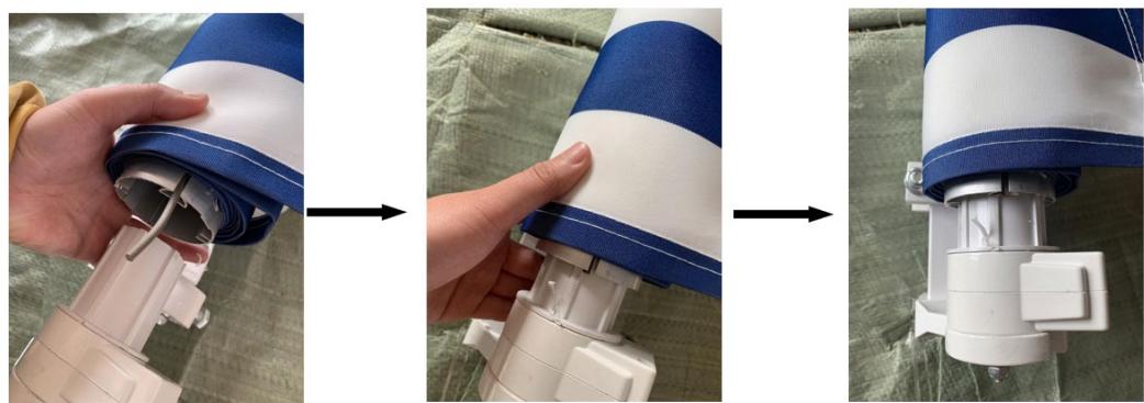
4) Push the thin one end of fabric with liner inserted into gauges on roller, then put the thick one end through front bar and put another thick one into valance.
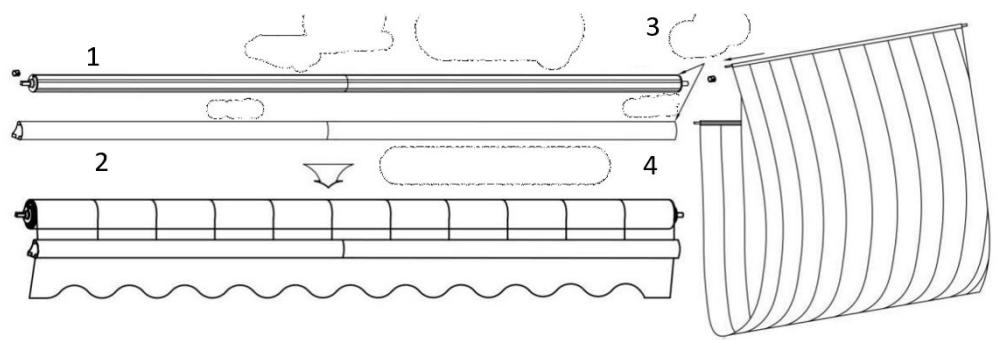
1: Roller
2: Front Bar
3: Insert thin liner into roller
4: Insert thick liner into front bar
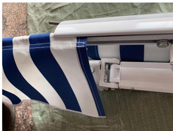
Attention: The fabric has two sides: front and back. The back side is with hem facing downwards.
Demonstration

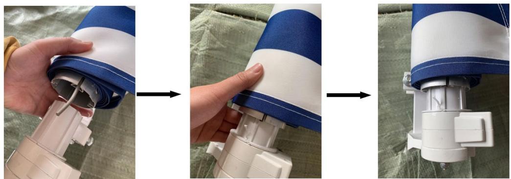
(1) Insert thin liner into roller

(2) Insert roller into right shaft cover
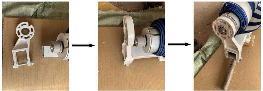
(3) Insert roller into left shaft and left roller support
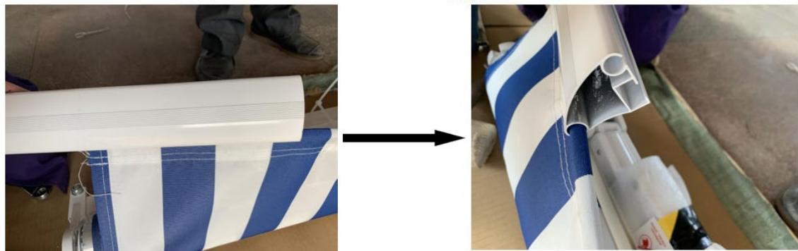
(4) Insert thick liner into front bar
6. Front Bar Wrist Support Assembly
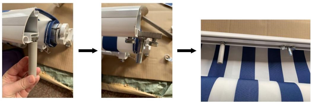
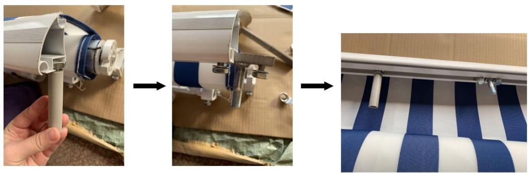
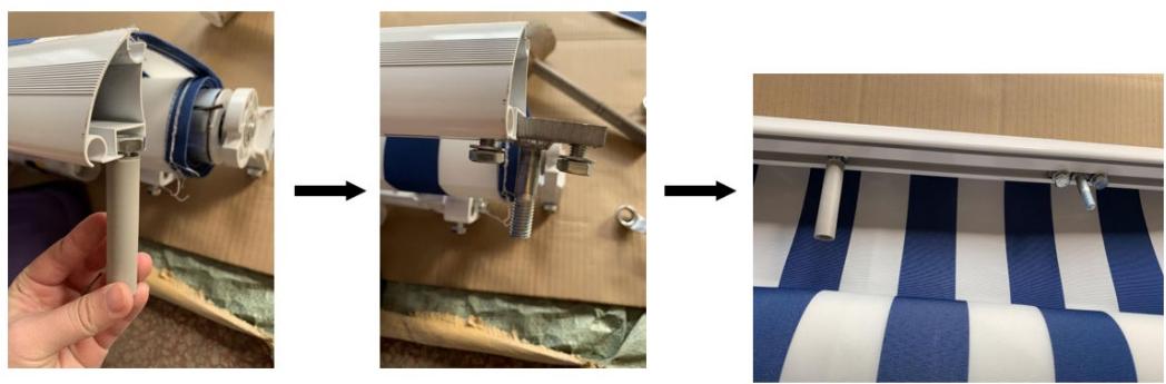
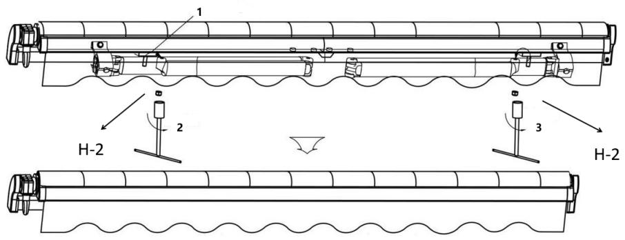
1) Slide the arm bar link(H-1) and blocker (H-3) into the wedge-shaped front bar through the large through/slot.
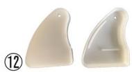
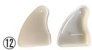
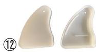
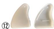
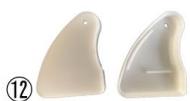
2) Put both the left and right plastic covers(H-4) on each end of the front bar.

3) Setting position of whole awning: Make sure two arms are tied tightly to torsion bar, move arm bar link (H-1) until it connects with front bar wrist. Align the front bar and roller, tighten bolt (H-2) of two front bar wrist support upwardly by screwdriver. Then fasten self locking nut M10 (a) with bolts up to 95% tight using ribbon tube spanner.
4) Finally setting blocker (H-3) in center of two arms, fasten it when awning is opened.

1: Insert in
2: Tight
3: Tight
Demonstration
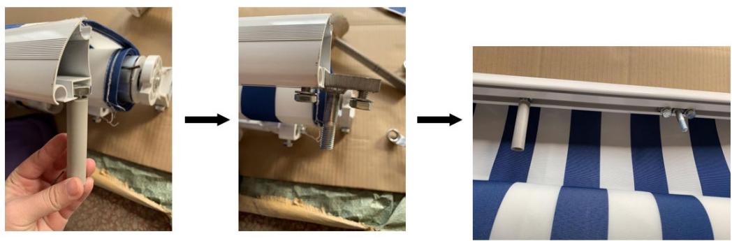
(1) Slide the arm bar link and blocker into the front bar
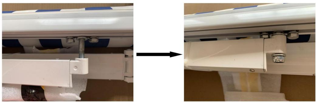
(2) Insert the arm bar link into the arms and tighten the bolt
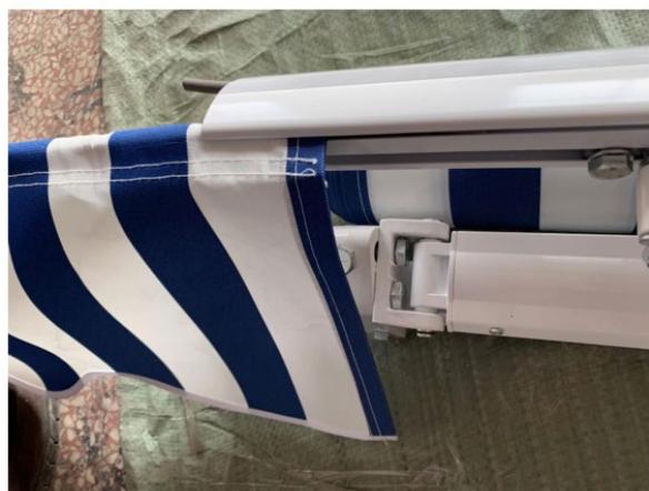
(3) Insert the valance into front bar
7. Finishing Awning Assembly
1) At this point, it is safe to cut the safety sleeves that hold the arms and torsion bar down. Awning assembly is complete!
2) Now, proceed to the wall mounting section.
WALL MOUNTING ASSEMBLY
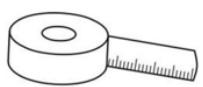
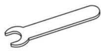
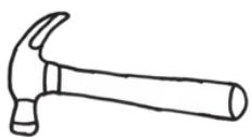
Please prepare the following tools before installation (not included with the product)
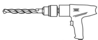
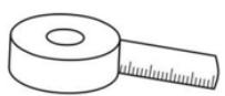
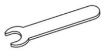
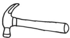
1

2
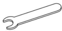
3
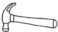
4
1- Power drill with drilling bit of φ 14
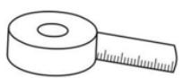
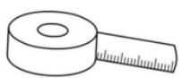
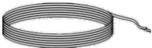
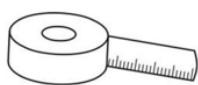
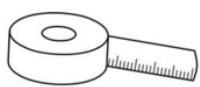
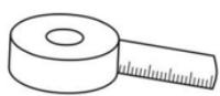
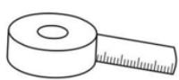
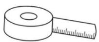
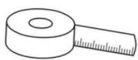
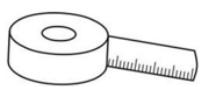
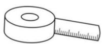
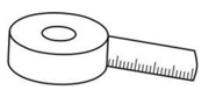
2- Tape
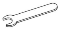
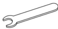
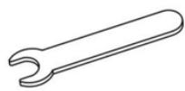
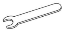
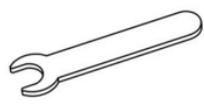
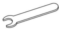
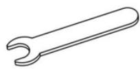
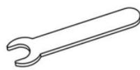
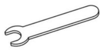
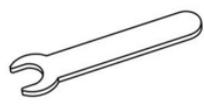
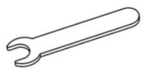
3- Wrench (wrenches of M10 and M12)
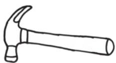
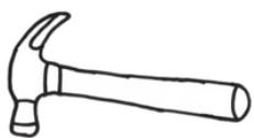
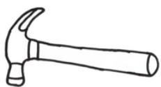
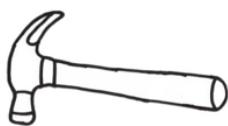
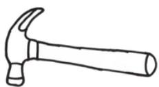
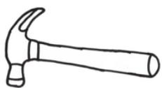
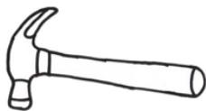
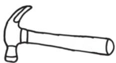
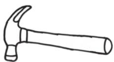
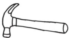
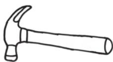
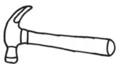
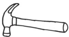
4- Hammer
1. Installation Procedure
1) Measure the distance along the wall where it can be placed. Drill holes for wall brackets on the wall according to the installation distances and height of the wall brackets. The diameter and depth of hole must be the same as expansion bolts.
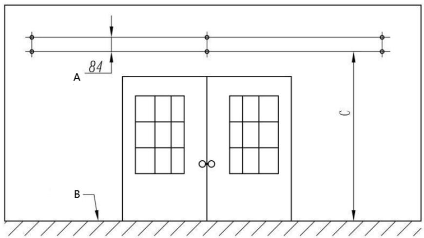
A. 3.5 Inch
B. Ground
Note:
• The holes of each group must be on the same line in transversal direction and vertical direction.
• It is recommended to draw lines on the wall first to ensure precise position and size of the holes.
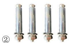
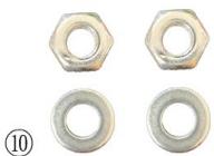
2) Hammer all the expansion bolts into the holes. Then take down the nuts and washer.
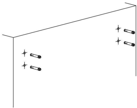
Note:
• The expansion bolts must be hammered into the wall completely.
• The bolts must be stick out of the wall so that the wall brackets can be installed on it.
- The nut and washer might be separated from the bolt during process of transportation, please put them back into their original positions before hammering them into the wall.
3) Take down the original bolts of the wall brackets as shown in the figure, use expansion bolts to fix the wall brackets on the wall. Do not tighten completely, leave wall brackets to stay on the wall with little movement.

1- Make sure all the all bases are on the same horizontal line
- Installation distance between wall brackets
| Awning < 3m | Only 2 wall brackets for each end of torsion bars |
| Awning 3.5m ~ 4.5m | 2 wall brackets at each end of torsion bar, a middle bracket in between distance of 2 arm shoulders (arm brackets refer to steps of assembly 6) |
| Awning > 5m | 2 wall brackets at each end of torsion bar, 2 middle brackets divide into equal length in between distance of 2 arm shoulders at each end of torsion bars. (steps of assembly 6) |
4) As shown in the figure, we recommend making the awning surface to form an angle of about 80 degrees with the wall when it is open.
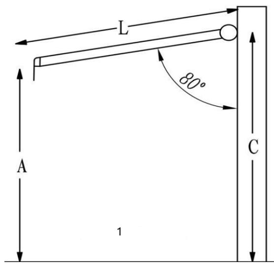
1- Side view
You can follow this formula: C = A + 0.17*L
(A: The height of front bar you desire; L: The length of the arm stretch out; C: The height of wall brackets)
5) Install the awning on the wall brackets according to "Installation distances between wall brackets" above, put the original bolts on the wall brackets and tighten them. Finally fasten all expansion bolts.


CAUTION!
- PROPER LOCATION OF THE BRACKETS IS THE MOST IMPORTANT ASPECT OF THE AWNING INSTALLATION.
- IT IS CRITICAL THAT YOU FASTEN ALL THE MOUNTING BRACKETS TO STUDS, JOISTS, HEADERS OR OTHER MAJOR STRUCTURAL COMPONENTS.

WARNING!
FAILURE TO SECURELY FASTEN ALL THE BRACKETS TO THE WALL COULD RESULT IN THE COLLAPSE OF THE AWNING AND CAUSE PERSONAL INJURY OR DEATH.
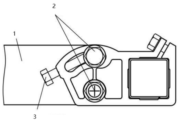
3. Instruction for front side levelling
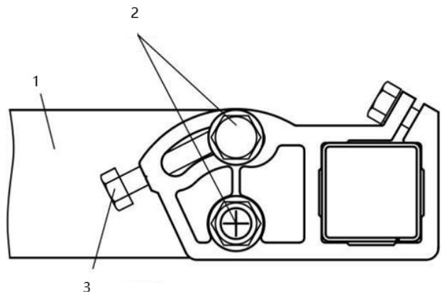
1- Arm
2- Locking Nuts
3- Jack Bolt
- Loosen the locking nuts.
- Turn the jack bolt to adjust pitch Adjust the arm until the front side.
- stays in horizontal line.
- Tighten the locking nuts.
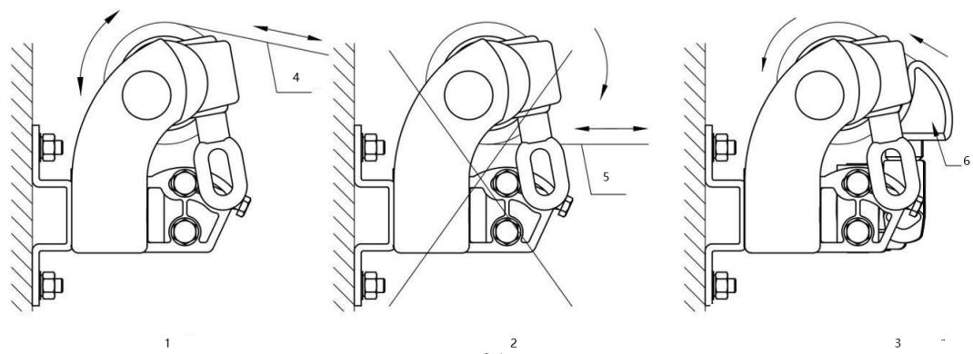
Common Mistakes
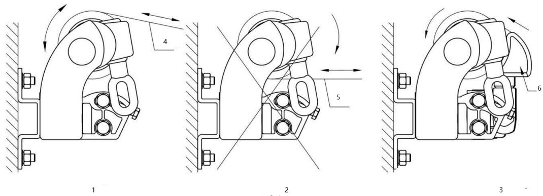
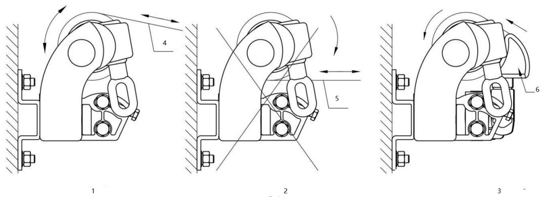
1- Correct operation
2- Wrong operation
3- Warning: When the front bar touches the roller as shown in the figure, don't try to make them closer, otherwise the product might be damaged.
4- Fabric
5- Fabric
6- Front bar
FAQ:
What if the fabric wraps unevenly or the two arms cannot open together at the same time?
Answer: Look at the stability of two arms and adjust the front bar wrist of the faster arm outwards accordingly.

Read “Instructions for installation and operation” carefully before installation. Keep the instruction in a safe place for future reference.
Parts list
To support the structure during mounting it is recommended that two people install this product. The DIY awning should only be attached to a strong and stable walls. Please first check that you have all the components listed before proceeding.
Components Supplied


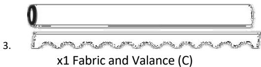
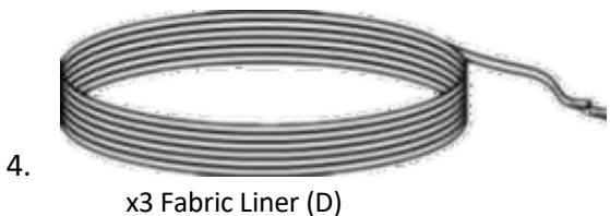



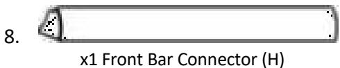
Screw Bag Listing (For 2.0m / 2.5m / 3.0m)
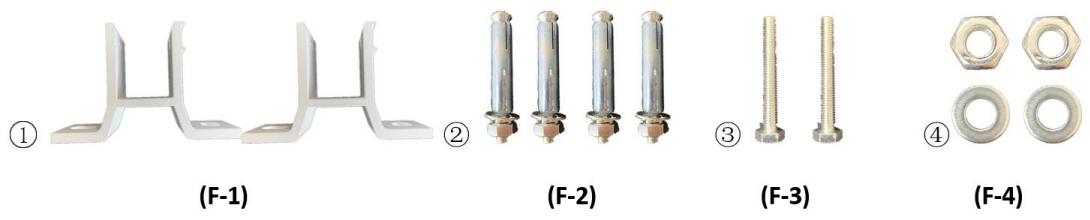
Part-F: Wall Bracket Accessories
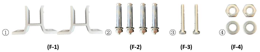
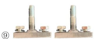
F-1: x2 Wall Bracket
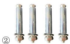
F-2: x4 Expanding Bolt
F-3: x2 Bolt M8x60
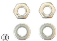
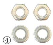
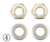
F-4: x2 Bolt M8 + Washer ∅8
Part-G: Roller&Torsion Bar Accessories
(G-1)

(G-2)
(G-3)
(G-4)
G-1: x4 Bolt M6 x 45
G-2: x4 Bolt M6+ Washer ∅6
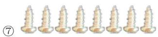
G-3: x8 Fixing Screw M4 x 15
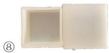
G-4: x2 Plastic Cover
Part-H: Front Bar Accessories
(H-1)
(H-2)
④
(H-3)
(H-4)
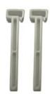
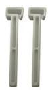
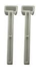
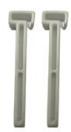
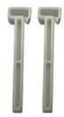
H-1: x2 Arm Bar Link
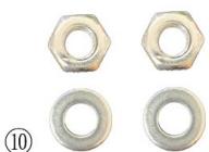
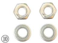
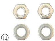
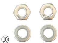
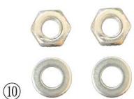
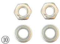
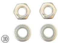
H-2: x2 Bolt M10+ Washer ∅10
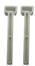
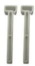
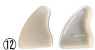
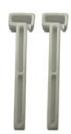
H-3: x2 Blocker
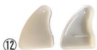
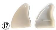
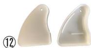
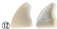
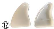
H-4: x2 Plastic Cover
13

(H-5)
14

(G-3)&(H-6)
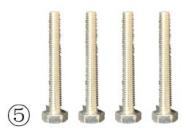
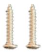
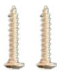
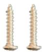
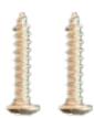
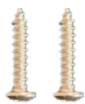
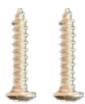
H-5: x2 Fixing Screw M8 x 20
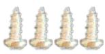
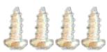
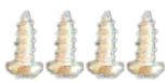
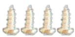
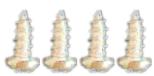
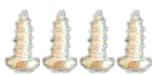
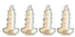
(G-3) &(H-6): x4 Fixing Screw M4x15

A: A-Roller
B: B-Roller
G: Złącze
G-3: Śruba
Demonstracja

4. Łączenie ramion
1

2

3
4
Notatka:
1- Widok z boku

UWAGA!
- PRAWIDŁOWE UMIEJSCOWIENIE UCHWYTÓW JEST NAJWAŻNIEJSZYM ASPEKTEM INSTALACJI MARKIZY.
- KONIECZNE JEST, ABY WSZYSTKIE WSPORNIKI MONTAŻOWE BYŁY PRZYMOCOWANE DO SŁUPKÓW, BELK, NADGŁÓWKÓW LUB INNYCH GŁÓWNYCH ELEMENTÓW KONSTRUKCYJNYCH.

OSTRZEŻENIE:
NIEPRAWIDŁOWE ZAMONTOWANIE WSZYSTKICH UCHWYTÓW DO ŚCIANY MOŻE SPOWODOWAĆ ZAŁAMANIE SIĘ MARKIZY I SPOWODOWAĆ OBRAŻENIA CIAŁA LUB ŚMIERĆ.
(B-Roller; B-Front Bar; B-Torsion Bar; B-Arm)
x1 Tkanina i lambrekin (C)
4.

x1 Korba ręczna (E)
6.

(H-1)
(H-2)
④
(H-3)
(H-4)
A: A-Roller
B: B-válec
G: Konektor
G-3: Šroub
Demonstrace

4. Spojovací ramena
A: Rameno A
B: Rameno B
1
2

3

4
Poznámka:
1- Boční pohled

UPOZORNĚNÍ!
- SPRÁVNÉ UMÍSTĚNÍ DRŽÁKŮ JE NEJDŮLEŽITĚJŠÍM ASPEKTEM MONTÁŽE MARKÝZY.
JE DÜLEŽITÉ, ABY STE VŠECHNY MONTÁŽNÍ DRŽÁKY PŘIPEVNILI NA STOJÁKY, NOSNÍKY, HLAVY NEBO JINÉ HLAVNÍ KONSTRUKČNÍ KOMPONENTY.

VAROVÁNÍ:
NEBEZPEČNÉ PŘIPEVNĚNÍ VŠECH DRŽÁKŮ NA STĚNU MŮŽE MÍT ZA NÁSLEDEK ZRUŠENÍ MARKÝZY A ZPŮSOBIT ZRANĚNÍ NEBO SMRT.
1- Rameno
2- Pojistné matice
3- Jack Bolt
x1 látka a volán (C)
4.
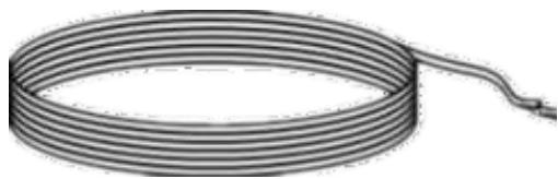
x1 ruční klika (E)
6.

(H-1)
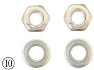
(H-2)
④
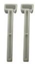
(H-3)
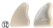
(H-4)
H-1: x2 Arm Bar Link
H-2: x2 Šroub M10+ Podložka ∅10
H-3: x2 blokátor
H-4: x2 Plastový kryt
13

(H-5)
14
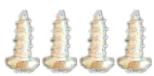
(G-3)&(H-6)
H-5: x2 Upevňovací šroub M8 x 20
(G-3) & (H-6): x4 Upevňovací šroub M4x15

A : A-Rouleau
B : Rouleau B
G : Connecteur
G-3 : Boulon
Démonstration

C : Tissu
1
2
3
4
Note:
1- Vue de côté

ATTENTION!
- L'EMPLACEMENT APPROPRIÉ DES SUPPORTS EST L'ASPECT LE PLUS IMPORTANT DE L'INSTALLATION DE L'AUVENT.
- IL EST ESSENTIEL DE FIXER TOUS LES SUPPORTS DE MONTAGE AUX GOUJONS, SOLIVES, LISERES OU AUTRES COMPOSANTS STRUCTURELS MAJEURS.

AVERTISSEMENT :
LE FAIT DE NE PAS FIXER SOLIDEMENT TOUS LES SUPPORTS AU MUR PEUT ENTRAÎNER L'EFFONDREMENT DE L'AUVENT ET CAUSER DES BLESSURES CORPORELLES OU LA MORT.
(B-Roller; B-Barre Avant; B-Barre de Torsion; B-Bras)
x1 Manivelle (E)
6.

(H-1)

(H-2)
④

(H-3)

(H-4)
A: A-Roller
B: Rullo B
G: Connettore
G-3: Bullone
Dimostrazione

3. Collegamento barre anteriori
A: Braccio A
B: Braccio B
C: Tessuto
1

2

3
4
Nota:
1- Vista laterale

ATTENZIONE!
x1 Tessuto e volant (C)
4.
x1 Manovella (E)
6.

(F-1)
(F-2)

(F-3)
(F-4)
F-3: x2 Bullone M8x60
F-4: x2 Bullone M8 + Rondella ∅8
G-2: x4 Bullone M6+ Rondella ∅6
(H-1)

(H-2)
④
(H-3)
(H-4)
H-2: x2 Bullone M10+ Rondella ∅10
H-3: x2 Bloccante
H-4: x2 Copertura in plastica
13
(H-5)
14
(G-3)&(H-6)
A: Rodillo A
B: B-Roller
G: Conector
G-3: Perno
Demostración

A: Brazo A
B: Brazo B
C: Tela
(3) Inserte la cenefa en la barra delantera
1
2
3
4
Nota:
1- Vista lateral

¡ADVERTENCIA!
x3 Forro de tela (D)
5.

x1 Manivela manual (E)
6.

(H-1)

(H-2)
④
(H-3)
(H-4)
A: A-görgő
B: B-görgő
G: Csatlakozó
G-3: Csavar
Bemutató

4. Összekötő karok
A: A-kar
B: B-kar
C: Szövet
1
2
3
4
Megjegyzés:
1- Oldalnézet

VIGYÁZAT!
- A NAPELLENZŐ FELSZERELÉSÉNEK LEGFONTOSABB SZEMPONTJA A KONZOLOK MEGFELELŐ ELHELYEZÉSE.
- KRITIKUS FONTOSSÁGÚ, HOGY AZ ÖSSZES RÖGZÍTŐ KONZOLT RÖGZÍTSE A CSAPOKHOZ, GERENDÁKHOZ, GERENDAVEZETÉKEKHEZ VAGY MÁS FÓBB SZERKEZETI ELEMEKHEZ.

VIGYÁZAT:
HA NEM RÖGZÍTI BIZTONSÁGOSAN AZ ÖSSZES KONZOLT A FALHOZ, AZ A NAPELLENZŐ ÖSSZEOMLÁSÁHOZ VEZETHET, ÉS SZEMÉLYI SÉRÜLÉST VAGY HALÁLT OKOZHAT.
x3 szövet bélés (D)
5.

x1 kézi kurbli (E)
6.

(H-1)

(H-2)
④
(H-3)

(H-4)
A: A-rulle
B: B-rulle
G: Stik
G-3: Bolt
Demonstration

4. Forbindelsesarme
C: Stof
(1) Sæt den tynde liner ind i rullen

1
2
3
4
1- Boremaskine med borekrone på φ 14
2- Bånd
3- Skruenøgle (M10- og M12-nøgler)
4- Hammer
1. Installationsprocedure
Bemærk:
1- Set fra siden

OBS!
- KORREKT PLACERING AF BESLAGENE ER DET VIGTIGSTE ASPEKT AF MARKISEMONTERINGEN.
- DET ER VIGTIGT, AT DU FASTG∅R ALLE MONTERINGSBESLAGENE TIL STOLPER, BJÆLKER, OVERLIGGERE ELLER ANDRE ST∅RRE STRUKTURELLE KOMPONENTER.

OBS!
HVIS IKKE ALLE BESLAGENE ER FASTGJORT SIKKERT TIL VÄGGEN, KAN DET RESULTERE I, AT MARKISEN FALDER SAMMEN OG FORÅRSAGE PERSONSKADE ELLER D∅D.
OFTE STILLEDE SP∅RGSMÅL:
(A-Front Bar; A-Torsion Bar; A-Arm)
x1 Hoveddel - venstre (inkl. rulle, frontstang, torsionsstang og arm)

(B-Roller; B-Front Bar; B-Torsion Bar; B-Arm)
x3 Stofforing (D)

x1 Håndsving (E)

x1 Torsionsstang-stik (F)

x1 Rullestik (G)

x1 Front Bar Connector (H)
Liste over skrueposer (til 2,0 m / 2,5 m / 3,0 m)
(H-1)
(H-2)
④

(H-3)
(H-4)
H-1: x2 Arm Bar Link
H-2: x2 Bolt M10+ Skive ∅10
H-3: x2-blokering
H-4: x2 plastikdæksel
13

(H-5)
14
(G-3)&(H-6)
V: A-rulla
B: B-rulla
G: Liitin
G-3: Pultti
Mielenosoitus

V: A-Arm
B: B-varsi
C: Kangas
D: Kangasvuoraukset
Mielenosoitus
(3) Aseta suojapelti etutankoon
1
2
3
4
1- Porakone, jossa on φ 14 pora
2- Nauha
3- Jakoavain (M10- ja M12-avaimet)
4- Vasara
1. Asennusmenettely
Huomautus:
1- Sivunäkymä

HUOMIO!
- KIINNIKKEIDEN OIKEA SIJAINTI ON MERKITTIEN ASENNUKSEN TÄRKEIN NÄKÖKOHDAT.
- ON TÄRKEÄÄ, ETTÄ KIINNITTÄT KAIKKI KIINNIKKEET NASTOJEN, PALKKIEN, PALOJEN TAI MUIHIN TÄRKEIHIN RAKENNEOSIEN.

VAROITUS!
KAIKKIEN KIINNIKKEIDEN TURVALLISESTI SEINÄÄN KIINNITTÄMINEN VOI AIHEUTTAA MARKKINAN LAATUMISEN JA AIHEUTTAA HENKILÖVAmman TAI KUOLEMAN.
1- Arm
2- Lukitusmutterit
3- Jack Bolt
(B-rulla; B-etutanko; B-vääntötanko; B-varsi)
x3 kangasvuori (D)
5.

x1 käsikampi (E)
6.

(H-1)

(H-2)
④
(H-3)
(H-4)
H-1: x2 Varsitangon linkki
H-2: x2 Pultti M10+ Aluslevy ∅10
H-3: x2 esto
H-4: x2 Muovikansi
⑬
(H-5)
14
(G-3)&(H-6)
A: A-rol
B: B-rol
G: Aansluiting
G-3: Bout
Demonstratie

2. Torsiestaven verbinden
3. Frontbalken verbinden
4. Verbindende armen
A: A-arm
B: B-arm
5. Stoffen assemblage
C: Stof
D: Stoffen voeringkoorden
Demonstratie
1
2

3
4
Opmerking:
1- Zijaanzicht

LET OP!
- DE JUISTE PLAATS VAN DE BEUGELS IS HET BELANGRIJKSTE ASPECT VAN DE INSTALLATIE VAN DE LUIFEL.
- HET IS VAN CRUCIAAL BELANG DAT U ALLE MONTAGEBEUGELS AAN DE STUDS, BALKEN, KOPPEN OF ANDERE BELANGRIJKE STRUCTUURONDERDELEN BEVESTIGT.

WAARSCHUWING!
ALS NIET ALLE BEUGELS GOED AAN DE MUUR WORDEN BEVESTIGD, KAN DIT RESULTEREN IN HET INKLAPPEN VAN DE LUIFEL EN DIT KAN LEIDEN TOT PERSOONLIJK LETSEL OF DE DOOD.
1- Arm
2- Borgmoeren
3- Krikbout
(B-Roller; B-Voorste stang; B-Torsiestang; B-Arm)
x1 Stof en Volant (C)
4.
x3 Stoffen voering (D)
5.

x1 Handzwengel (E)
6.

(H-1)
(H-2)
④
(H-3)

(H-4)
H-1: x2 Armstangverbinding
H-2: x2 Bout M10+ Ring ∅10
H-3: x2 Blokker
H-4: x2 kunststof afdekking
13

(H-5)
14
(G-3)&(H-6)
A: A-Roller
B: B-Roller
G: Kobling
G-3: Bolt
Demonstrasjon

4. Koblingsarmer
A: A-arm
B: B-arm
5. Stoffmontering
C: Stoff
Sett den tykke foringen og den tynne foringen inn i begge ender av det store stoffstykket.
1: Rulle
2: Frontstang
3: Sett tynn liner inn i rullen
4: Sett inn tykk foring i frontstangen
(1) Sett tynn liner inn i rullen

(4) Sett tykk foring inn i frontstangen
1: Sett inn
2: Tett
3: Tett
Demonstrasjon
(1) Skyv armstanglenken og blokkeringen inn i frontstangen

(3) Sett kappen inn i frontstangen
7. Etterbehandling av markisemontering
1

2
3
4
Note:
1- Sidevisning

OBS!!!
- RIKTIG PLASSERING AV BRAKETENE ER DET VIKTIGSTE ASPEKTE AV MARKISENS INSTALLASJON.
- DET ER KRITISK AT DU FESTER ALLE MONTERINGSBRAKKETTER TIL STINDER, BJELKERE, HOSDER ELLER ANDRE ST∅RRE STRUKTURELLE KOMPONENTER.

ADVARSEL!
MANGLENDE Å FESTE ALLE BRAKETENE SIKKERT TIL VEGGEN KAN F∅RE TIL AT MARKISEN KAN SLÅS OG FORÅRSAKE PERSONSKADE ELLER D∅D.
1- Væpne
2- Låsemuttere
3- Jack Bolt
- Løsne låsemutrene.
- Vri jekkbolten for å justere stigning. Juster armen til forsiden.
- forblir i horisontal linje.
- Stram läsemutrene.
Vanlig Feil


Skrueposeliste (for 2,0 m / 2,5 m / 3,0 m)
Del-F : Tilbehør til veggbrakett
F-1: x2 Veggbrakett
F-2: x4 ekspanderende bolt
F-3: x2 Bolt M8x60
F-4: x2 Bolt M8 + Skive ∅8
(H-1)

(H-2)
④

(H-3)
(H-4)
H-1: x2 Arm Bar Link
H-2: x2 Bolt M10+ Skive ∅10
H-3: x2 Blocker
H-4: x2 Plastdeksel
13

(H-5)
14

(G-3)&(H-6)
H-5: x2 festeskrue M8 x 20
(G-3) &(H-6): x4 festeskrue M4x15

A: A-Roller
B: B-Roller
G: Anslutning
G-3: Bult
Demonstration

A: A-arm
B: B-arm
5. Tygmontering
C: Tyg
D: Liner i tyg
Demonstration
(1) Sätt in tunt foder i rullen
1: Sätt in
2: Tight
3: Tight
Demonstration
1
2
3
4
Notera:
1- Sidovy

OBS!
- RÄTT PLACERING AV FÄSTERNA ÄR DEN VIKTIGASTE ASPEKTEN AV MARKISINSTALLATIONEN.
- DET ÄR KRITISKT ATT DU FÄST ALLA MONTERINGSBESLAG TILL REGLAR, BJÄLLAR, SKRUVELLER ELLER ANDRA STÖRRE STRUKTURELLA KOMPONENTER.

WARNING!
UNDERLÅTANDE ATT FÄSTA ALLA FÄSTERNA SÄKERT PÅ VÄGGEN KAN RESULTAT TILL ATT MARKISEN KOLPSAR OCH ORSAKA PERSONSKADA ELLER DÖDSFALL.
(A-Front Bar; A-Torsion Bar; A-Arm)
(B-Roller; B-Front Bar; B-Torsion Bar; B-Arm)
x3 tygfoder (D)
5.

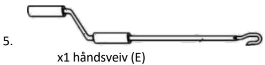
x1 handvev (E)
6.

x1 Torsion Bar Connector (F)
7.
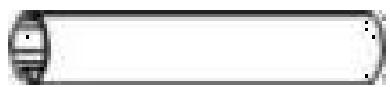
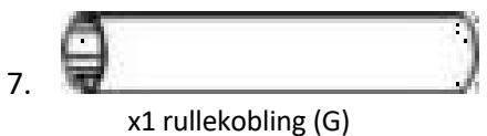
x1 rullkontakt (G)
8.

(H-1)

(H-2)
④
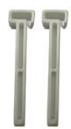
(H-3)
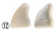
(H-4)
H-1: x2 Arm Bar Link
H-2: x2 Bult M10+ Bricka ∅10
H-3: x2 Blocker
H-4: x2 Plastskydd
13
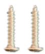
(H-5)
A: A-Roller
B: Rolo B
G: Conector
G-3: Parafuso
Demonstração

3. Conectando Barras Frontais
A: Braço A
B: Braço B
C: Tecido
1: Rolo
2: Barra frontal
3: Insira o revestimento fino no rolo
4: Insira o revestimento grosso na barra frontal
(4) Insira o revestimento grosso na barra frontal
(3) Insira a saia na barra frontal
1
2

3
4
Observação:
1- Vista lateral

ATENÇÃO!
- A LOCALIZAÇÃO CORRETA DOS SUPORTES É O ASPECTO MAIS IMPORTANTE DA INSTALAÇÃO DO TOLDO.
- É FUNDAMENTAL QUE VOCÊ FIXE TODOS OS SUPORTES DE MONTAGEM A PINOS, VIGAS, CABEÇALHOS OU OUTROS COMPONENTES ESTRUTURAIS PRINCIPAIS.

CUIDADO!
NÃO FIXAR COM SEGURANÇA TODOS OS SUPORTES NA PAREDE PODE RESULTAR NO DESMORONAMENTO DO TOLDO E CAUSAR FERIMENTOS PESSOAIS OU MORTE.
x1 Tecido e Saia (C)
4.
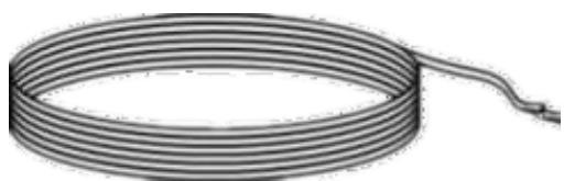
x1 Manivela (E)
6.

(H-1)
(H-2)
④

(H-3)
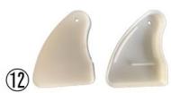
(H-4)
H-1: x2 Barra de braço Link
H-2: x2 Parafuso M10+ Arruela ∅10
H-3: x2 Bloqueador
H-4: x2 Capa de plástico
13
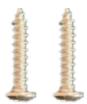
(H-5)
14
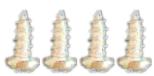
(G-3)&(H-6)
A: A-Roller
B: B-valec
G: Konektor
G-3: Skrutka
Demonštrácia

A: Rameno A
B: Rameno B
5. Zostava tkaniny
(2) Vložte tyč ramena do ramien a utiahnite skrutku

1
2
3
4
Poznámka:
1- Pohl'ad zboku

UPOZORNENIE!
- SPRÁVNE UMIESTNENIE DRŽIAK JE NAJDÔLEŽITEJŠÍM ASPEKTOM INŠTALÁCIE MARKÍZY.
- JE DÔLEŽITÉ, ABY STE VŠETKY MONTÁŽNE KONZOLKY PRIPEVNLILI NA STÍPY, PODPLÁŠKY, HLAVY ALEBO INÉ HLAVNÉ KONŠTRUKČNÉ KOMPONENTY.

VÝSTRAHA!
NEBEZPEČNÉ UPEVNENIE VŠETKÝCH DRŽIAK NA STENU MÔŽE SPÔSOBIT Ž ZRUŠENIE MARKÍZY A SPÔSOBENIE ZRANENIA ALEBO SMRTI.
1- Arm
2- Poistné matice
3- Jack Bolt
(A-predná tyč; A-torzná tyč; A-rameno)
(B-valec; B-predná tyč; B-torzná tyč; B-rameno)
1x ručná kl'uka (E)
6.

x1 konektor torznej tyče (F)
7.
(H-1)
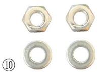
(H-2)
④

(H-3)

(H-4)
H-1: x2 Link Bar Link
H-2: x2 Skrutka M10+ Podložka ∅10
H-3: x2 blokátor
H-4: x2 plastový kryt
13
(H-5)
14
(G-3)&(H-6)
H-5: x2 Upevňovacia skrutka M8 x 20
(G-3) & (H-6): x4 Upevňovacia skrutka M4x15

A: A-Roller
В: В-ролка
G: Конектор
G-3: Болт
Демонстрация

4. Свързващи ръце
A: A-Ran
B: B-рамо
5. Монтаж на плат
С: Плат
D: Въжета от плат
Демонстрация
1
2
3

4
Забележка:
1- Изглед отстрани

ВНИМАНИЕ!
(H-1)

(H-2)
④

(H-3)

(H-4)
H-1: x2 Arm Bar Link
H-2: x2 болт M10+ шайба ∅10
H-3: x2 Блокер
A: A-Roller
B: B-Roller
Z: Σύνδεσμος
G-3: Μπουλόνι
Επίδειξη

A: A-Arm
B: B-Arm
Γ: Ύφασμα
1

2
3
4
Σημείωμα:
1- Πλαϊνή όψη

ΠΡΟΣΟΧΗ!
(A-Front Bar; A-Torsion Bar; A-Arm)
(B-Roller; B-Front Bar; B-Torsion Bar; B-Arm)
(F-1)
(F-2)
(F-3)
(F-4)
(H-1)
(H-2)
④
(H-3)
(H-4)
O: A-valjak
B: B-valjak
G: Konektor
G-3: Zasun
Demonstracija

3. Spajanje prednjih šipki
Sklop prednje šipke: Umetnite konektor prednje šipke (H) u desnu prednju šipku (B-prednja šipka), pričvrstite vijkom (H-6). Povežite lijevu prednju šipku (A-prednja šipka) s konektorom (H), pričvrstite je vijkom (H-6). Sada imate prednju šipku pune dužine.
O: A-prednja traka
B: B-prednja traka
H: Priključak
H-6: Zasun
Demonstracija

4. Spajanje ruku
O: A-ruka
B: B-ruka
5. Montaža tkanine
1) Pažljivo otvorite kutiju kako biste bili sigurni da tkanina i zastor nisu oštećeni.
2) Rasklopite komade tkanine tende. Trebali biste imati jedan veliki komad tkanine (C) i narukvicu s nazubljenim rubom. Također biste trebali imati tri užeta od tkanine, dva deblja i jedan tanji (D).
3) Provucite podstavu od tkanine, jednu deblju i jednu tanku, kroz oba kraja velike tkanine tende (C). Ovo može biti spor proces i najlakši je s dvoje ljudi.

C: Tkanina
D: Užad od tkanine
Demonstracija

Umetnite deblju i tanku podstavu u oba kraja velikog komada tkanine.
4) Gurnite jedan tanki kraj tkanine s podstavom umetnutom u mjerače na valjku, zatim provucite jedan deblji kraj kroz prednju prečku i stavite drugi deblji u zastor.
1: Valjak
2: Prednja traka
3: Umetnite tanku podlogu u valjak
4: Umetnite debelu podlogu u prednju šipku
(1) Umetnite tanku podlogu u valjak
(2) Umetnite valjak u desni poklopac osovine

(4) Umetnite debelu podlogu u prednju šipku
6. Sklop potpore za zglob s prednjom šipkom
1) Gurnite polugu poluge (H-1) i bloker (H-3) u klinastu prednju polugu kroz veliki prolaz/utor.
2) Stavite i lijevi i desni plastični poklopac (H-4) na oba kraja prednje šipke.

3) Postavljanje položaja cijele tende: Provjerite jesu li dvije ruke čvrsto vezane za torzionu šipku, pomaknite vezu poluge (H-1) dok se ne spoji sa zglobom prednje šipke. Poravnajte prednju šipku i valjak, zategnite vijak (H-2) dvaju nosača zgloba prednje šipke prema gore pomoću odvijača. Zatim pričvrstite samosigurnosnu maticu M10 (a) s vijcima do 95% pomoću vrpčastog cijevnog ključa.
4) Na kraju postavite blokator (H-3) u sredinu dva kraka, pričvrstite ga kada se tenda otvori.
1: Umetanje
2: Čvrsto
3: Čvrsto
Demonstracija

(1) Gurnite polugu ručke i bloker u prednju šipku

(2) Umetnite kariku poluge u ruke i zategnite vijak
(3) Umetnite zastor u prednju šipku
1
2
3
4
1- Električna bušilica sa svrdlom od φ 14
2- Traka
3- Ključ (ključevi M10 i M12)
4- Čekić
1. Instalacijski postupak
Bilješka:
- Ekspanzijski vijci moraju biti potpuno zabijeni u zid.
1- Pogled sa strane

OPREZ!
- ODGOVARAJUĆI POLOŽAJ KONZOLA NAJVAŽNIJI JE ASPEKT MONTAŽE TENDE.
- OD KRITIČNE JE VAŽNOSTI DA PRIČVRSTITE SVE MONTAŽNE NOSAČE NA SKLOPKE, GREDE, GLAVE ILI DRUGE VEĆE STRUKTURALNE KOMPONENTE.

UPOZORENJE!
PROPUST SIGURNO PRIČVRŠĆIVANJA SVIH NOSAČA NA ZID MOŽE DODJELI DO SRUŠAVANJA TENDE I UZROKOVATI OSOBNIH OZLJEDA ILI SMRT.
3. Upute za izravnavanje prednje strane
1- Ruka
2- Sigurnosne matice
3- Jack Bolt
- Otpustite sigurnosne matice.
- Okrenite vijak dizalice za podešavanje nagiba. Podesite ruku do prednje strane.
- ostaje u horizontalnoj liniji.
- Zategnite sigurnosne matice.
Uobičajeno Greške

1- Ispravan rad
2- Pogrešna operacija
3- Upozorenje: Kada prednja šipka dodirne valjak kao što je prikazano na slici, nemojte ih pokušavati približiti jer bi se u suprotnom proizvod mogao oštetiti.
4- Tkanina
5- Tkanina
6- Prednja traka
FAQ:
(A-prednja šipka; A-torzijska šipka; A-ruka)
(B-valjak; B-prednja šipka; B-torzijska šipka; B-ruka)
x1 Glavni dio - desno (uključuje valjak; prednju polugu; torzijsku polugu i ruku)
3.
x1 tkanina i zastor (C)
4.
x3 tkanina (D)
5.

x1 Ručna kurbla (E)
6.

(H-1)
(H-2)
④

(H-3)
(H-4)
H-1: x2 ručna veza
H-2: x2 Vijak M10+ Podloška ∅10
H-3: x2 bloker
H-4: x2 plastični poklopac
13
(H-5)
14

(G-3)&(H-6)
H-5: x2 pričvrsni vijak M8 x 20
(G-3) &(H-6): x4 pričvrsni vijak M4x15

A: A formos volelis
B: B formos volelis
G: Jungtis
G-3: Varžtas
Demonstracija

A: A-ranka
B: B ranka
5. Audinio surinkimas
C: Audinys
1: jdèkite
2: stora
3: stora
Demonstracija

1
2
3

4
Pastaba:
1- Vaizdas iš šono
Galite vadovautis šia formule: C = A + 0,17*L

ATSARGIAI!
- SVARBIAUSIAS TENTĖS MONTAVIMO ASPEKTAS – TINKAMAS KREKLIŲ VIETA.
- BÜTINA, KAD VISUS MONTAVIMO KRANTIKLIUS PRITvirtintumète PRIE SMIEGŲ, SIJŲ, GALVATŲ AR KITŲ PAGRINDINIŲ KONSTRUKCIJŲ KOMPONENTŲ.

JSPĖJIMAS!
NESPAUDUS SAUGIAI NEPRITvirtinti VISŲ KRONIALIŲ PRIE SIENOS, GALI SUDĖTI TENTĖ IR SUKELTI ASMENS SUŽALOJIMAS ARBA MIRTIS.
(H-1)
(H-2)
④
(H-3)
(H-4)
H-1: x2 rankos strypo jungtis
H-2: x2 Varžtas M10+ Poveržlė ∅10
H-3: x2 blokatorius
H-4: x2 plastikinis dangtelis
13
(H-5)
14
(G-3)&(H-6)
H-5: x2 tvirtinimo varžtas M8 x 20
(G-3) & (H-6): x4 Tvirtinimo varžtas M4x15

A: A-Roller
B: Rolă B
G: Conector
G-3: Bolt
Demonstrație

3. Conectarea barelor frontale
A: A-brat,
B: B-Brat
C: țesătură
1
2
3
4
Nota:
1- Vedere laterală

ATENTIE!
- LOCAREA CORECTA A SUPORTURILOR ESTE CEL MAI IMPORTANT ASPECT AL INSTALĂRII COPERTIZEI.
- ESTE CRITIC SĂ FIXĂȚI TOATE SUPORTELE DE MONTARE PE STUPTI, GRUPII, ANTETE SAU ALTE COMPONENTE STRUCTURALE MAJORE.

AVERTIZARE!
NEFIXAREA ÎN SIGURANȚĂ A TOȚI SUPORTURI DE PERETE PUTEA RESULTE LA PRIBEREA COPERTIZEI ȘI A PROVOCA RĂNIREA PERSONALĂ SAU MOARTEA.
x1 manivelă (E)
6.

(H-1)
(H-2)
④

(H-3)
(H-4)
A: A-Roller
B: B-valj
G: Konektor
G-3: Vijak
Demonstracija

3. Povezovanje sprednjih palic
4. Povezovalne roke
O: A-roka
B: B-roka
5. Montaža tkanine
C: Tkanina
D: vrvice iz blaga
Demonstracija

1: Valjček
2: sprednja vrstica
3: V valj vstavite tanko podlogo
4: V sprednjo palico vstavite debelo podlogo
(1) V valj vstavite tanko podlogo
(2) Vstavite valj v desni pokrov gredi
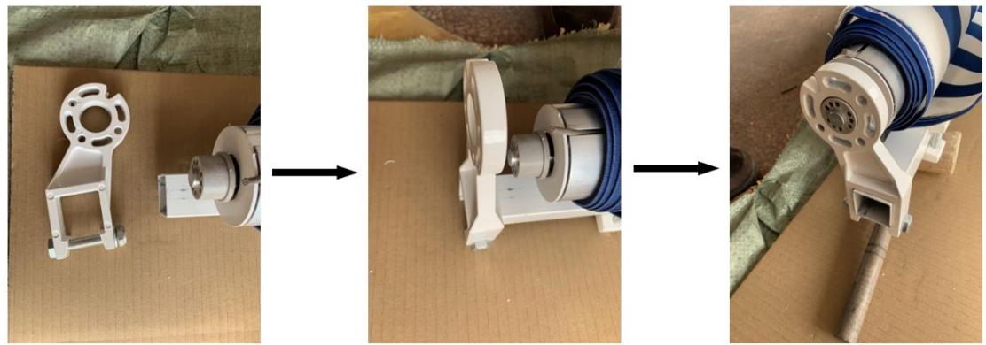
(3) Vstavite valj v levo gred in levi nosilec valja

(4) V sprednjo palico vstavite debelo podlogo
1: Vstavite
2: Tesno
3: Tesno
Demonstracija

(1) Potisnite povezavo droga in blokator v sprednji drog
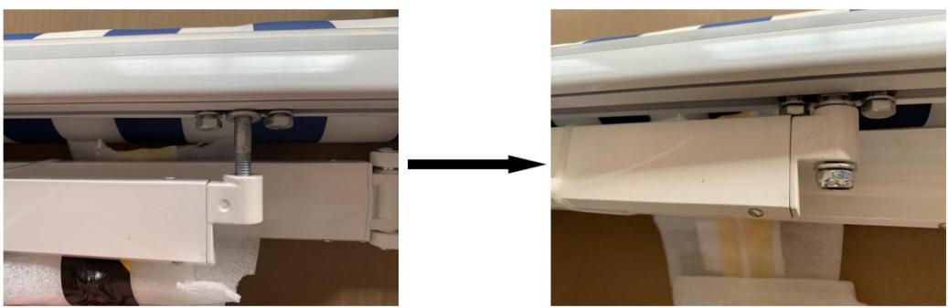
(2) Vstavite člen droga v roke in privijte vijak
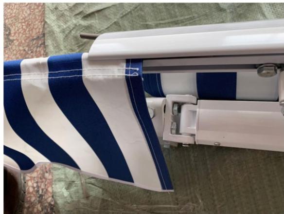
(3) Zaslon vstavite v sprednjo palico
1

2

3
4
1- Električni vrtalnik s svedrom φ 14
2- Trak
3- Ključ (ključ M10 in M12)
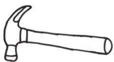
4- Kladivo
Opomba:
1- Stranski pogled
Sledite tej formuli: C = A + 0,17*L

POZOR!
- PRAVILNA LOKACIJA NOSILCEV JE NAJPOMEMBNEJŠI VIDIK NAMESTITEV TENDE.
- KLJUČNO JE POMEMBNO, DA VSE MONTAŽNE KONZOLE PRITRDITE NA STORITVE, GROVE, GLAVE ALI DRUGE VEČJE KONSTRUKCIJSKE KOMPONENTE.

OPOZORILO!
ČE VSEH NOSILCEV NE VARNO PRITRDITE NA STENO, SE LAHKO PRIVREDI, DA SE TENDA ZRUŠI IN POVZROČI TELESNE POŠKODBE ALI SMRT.
1- Arm
2- Zaklepne matice
3- Jack Bolt
- Odvijte zaklepne matice.
- Obrnite vijak dvigalke, da prilagodite naklon. Nastavite roko do sprednje strani.
- ostane v vodoravni liniji.
- Zategnite varovalne matice.
pogosta Napake
(A-prednji drog; A-torzijski drog; A-roka)
(B-roler; B-prednji drog; B-torzijski drog; B-roka)
x1 Glavni del - desno (vključuje valj; sprednji drog; torzijsko drog in roko)
3.

x1 tkanina in platno (C)
4.
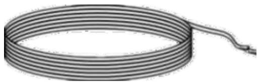
x3 Fabric Liner (D)
5.

x1 ročna gonilka (E)
6.

(H-1)

(H-2)
④
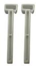
(H-3)
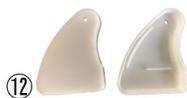
(H-4)
H-1: x2 povezava palice za roke
H-2: x2 vijak M10+ podložka ∅10
H-3: blokator x2
H-4: x2 plastični pokrov
13
(H-5)
14
(G-3)&(H-6)
H-5: x2 pritrdilni vijak M8 x 20
(G-3) &(H-6): x4 pritrdilni vijak M4x15
For the disposal of the device please consider and act according to the national and local rules and regulations.
CONTACT
expondo Polska sp. z o.o. sp. k.



- DEMONSTRATION
- VERBINDUNGSARME
- ANMERKUNG
- SEITENANSICHT
- ACHTUNG
- TECHNICAL DATA
- PURPOSE
- INSTALLATION
- ASSEMBLY
- CONNECTING ROLLER TUBES
- CONNECTING TORSION BARS
- CONNECTING FRONT BARS
- CONNECTING ARMS
- WARNING
- FABRIC ASSEMBLY
- FRONT BAR WRIST SUPPORT ASSEMBLY
- FINISHING AWNING ASSEMBLY
- WALL MOUNTING ASSEMBLY
- INSTALLATION PROCEDURE
- NOTE
- SIDE VIEW
- CAUTION
- INSTRUCTION FOR FRONT SIDE LEVELLING
- COMMON MISTAKES
- FAQ
- PARTS LIST
- DEMONSTRACJA
- ŁĄCZENIE RAMION
- NOTATKA
- WIDOK Z BOKU
- UWAGA
- OSTRZEŻENIE
- DEMONSTRACE
- SPOJOVACÍ RAMENA
- POZNÁMKA
- BOČNÍ POHLED
- UPOZORNĚNÍ
- VAROVÁNÍ
- DÉMONSTRATION
- VUE DE CÔTÉ
- ATTENTION
- AVERTISSEMENT
- DIMOSTRAZIONE
- COLLEGAMENTO BARRE ANTERIORI
- NOTA
- VISTA LATERALE
- ATTENZIONE
- DEMOSTRACIÓN
- VISTA LATERAL
- ¡ADVERTENCIA
- BEMUTATÓ
- ÖSSZEKÖTŐ KAROK
- MEGJEGYZÉS
- OLDALNÉZET
- VIGYÁZAT
- FORBINDELSESARME
- INSTALLATIONSPROCEDURE
- BEMÆRK
- SET FRA SIDEN
- OBS
- OFTE STILLEDE SP∅RGSMÅL
- MIELENOSOITUS
- ASENNUSMENETTELY
- HUOMAUTUS
- SIVUNÄKYMÄ
- HUOMIO
- VAROITUS
- DEMONSTRATIE
- TORSIESTAVEN VERBINDEN
- FRONTBALKEN VERBINDEN
- VERBINDENDE ARMEN
- STOFFEN ASSEMBLAGE
- OPMERKING
- ZIJAANZICHT
- LET OP
- WAARSCHUWING
- DEMONSTRASJON
- KOBLINGSARMER
- STOFFMONTERING
- ETTERBEHANDLING AV MARKISEMONTERING
- SIDEVISNING
- ADVARSEL
- VANLIG FEIL
- TYGMONTERING
- NOTERA
- SIDOVY
- DEMONSTRAÇÃO
- CONECTANDO BARRAS FRONTAIS
- OBSERVAÇÃO
- ATENÇÃO
- CUIDADO
- DEMONŠTRÁCIA
- ZOSTAVA TKANINY
- POHL'AD ZBOKU
- UPOZORNENIE
- VÝSTRAHA
- ДЕМОНСТРАЦИЯ
- СВЪРЗВАЩИ РЪЦЕ
- МОНТАЖ НА ПЛАТ
- ЗАБЕЛЕЖКА
- ИЗГЛЕД ОТСТРАНИ
- ВНИМАНИЕ
- ΣΗΜΕΊΩΜΑ
- ΠΛΑΪΝΉ ΌΨΗ
- ΠΡΟΣΟΧΗ
- DEMONSTRACIJA
- SPAJANJE PREDNJIH ŠIPKI
- SPAJANJE RUKU
- MONTAŽA TKANINE
- SKLOP POTPORE ZA ZGLOB S PREDNJOM ŠIPKOM
- INSTALACIJSKI POSTUPAK
- BILJEŠKA
- POGLED SA STRANE
- OPREZ
- UPOZORENJE
- UPUTE ZA IZRAVNAVANJE PREDNJE STRANE
- UOBIČAJENO GREŠKE
- AUDINIO SURINKIMAS
- PASTABA
- VAIZDAS IŠ ŠONO
- ATSARGIAI
- JSPĖJIMAS
- DEMONSTRAȚIE
- CONECTAREA BARELOR FRONTALE
- VEDERE LATERALĂ
- ATENTIE
- AVERTIZARE
- POVEZOVANJE SPREDNJIH PALIC
- POVEZOVALNE ROKE
- OPOMBA
- STRANSKI POGLED
- POZOR
- OPOZORILO
- POGOSTA NAPAKE
- CONTACT
Brand : Uniprodo
Model : UNI_RA_01
Category : Washing machine