FLOORTEC R 680 - Scrubber NILFISK - Free user manual and instructions
Find the device manual for free FLOORTEC R 680 NILFISK in PDF.

| Product type | Scrubber (sweeper) |
| Brand | NILFISK |
| Model | FLOORTEC R 680 |
| Cleaning width (1 side brush) | 1,054 mm |
| Cleaning width (2 side brushes) | 1,308 mm |
| Machine length | 1,776 mm |
| Machine width (1 side brush) | 1,208 mm |
| Machine width (2 side brushes) | 1,310 mm |
| Maximum machine height (at steering wheel) | 1,350 mm |
| Waste container capacity | 130 L |
| Total weight in working order (with operator) | 743 kg |
| Engine | Briggs & Stratton Vanguard 9 HP (6.7 kW) |
| Electrical supply | 2 batteries 12 V – 70 Ah (24 V) |
| Maximum forward speed | 7 km/h |
| Maximum reverse speed | 3 km/h |
| Maximum climbable slope | 20% |
| Minimum turning radius | 1,685 mm |
| Dust filter | Paper, area 3.6 m², filtration 15-20 μm |
| Vibration level (arm) | < 2.5 m/s² |
| Vibration level (body) | < 0.5 m/s² |
| Sound pressure level (operator) | 80 dB(A) ± 3 dB(A) |
| Safety | Emergency button, parking brake, safety micro-switches |
| Maintenance | Scheduled plan: oil, brushes, filters check, etc. |
| Spare parts | Use genuine parts, catalog available |
Frequently Asked Questions - FLOORTEC R 680 NILFISK
User questions about FLOORTEC R 680 NILFISK
0 question about this device. Answer the ones you know or ask your own.
Ask a new question about this device
Download the instructions for your Scrubber in PDF format for free! Find your manual FLOORTEC R 680 - NILFISK and take your electronic device back in hand. On this page are published all the documents necessary for the use of your device. FLOORTEC R 680 by NILFISK.
USER MANUAL FLOORTEC R 680 NILFISK
Conformity certificate
IiToTIOIntIKo OuMóPφωnc
Undertegnede attesterer herved, at
The undersigned certify that the above
mentioned model is produced in
accordance with the following directives
and standards

O KATWl UTOVyepauevoc TIOITOTIOIE OI n
Tapaywyn Tou PtoavawepeEvTOGovTeAou
yivetaouwva e Tcakoloueoc oynie

BbIeYka3aHHoM MoJeN N3rOToBnHeHa
B COOTBETCTBUN CO CJIeIyIOUIMM
DInpeKTHBaMIMCTaHapTaMn.

EC Machinery Directive 98/37/EC
EN ISO 12100-1, EN ISO 12100-2, EN 294, EN 349
EC EMC Directive 89/336/EEC
EN 60335-1, EN 60335-2-72
EN 61000, EN 50366
CONSERVATION DU MANUEL 2
DECLARATION DE CONFORMITE 2
DONNEES D'IDENTIFICATION 2
STRUCTURE DE LA MACHINE 6
TABLEAU DE BORD ET COMMANDES 8
ACCESSIONS / OPTIONS 9
CHARACTERISTIQUES TECHNIQUES 9
SCHEMA ELECTRIQUE 11
SCHEMA HYDRALIQUE DU SYSTEME DE SOULEVEMENT DU CONTENEUR DECHETS 13
SCHEMA HYDRAULIQUE DU SYSTEME DE TRACTION 13
UTILISATION 14
AVANT LA MISE EN MARCHE 14
MISE EN MARCHE ET ARRET DE LA MACHINE 14
MACHINE AU TRAVAIL 15
VIDANGE DU CONTENEUR DECHETS 16
APRES L'UTILISATION DE LA MACHINE 17
DEPLACEMENT PAR POUSSEE / REMORQUAGE DE LA MACHINE 17
REGLAGE DU FEU DE TRAVAIL (optionnel) 17
INACTIVITE PROLONGEE DE LA MACHINE 17
PREMIERE PERIODE D'UTILISATION 17
ENTRETIEN 18
PLAN D'ENTRETIEN PROGRAMME 18
CONTROLE ET REGLAGE DE LA HAUTEUR DU BALAI CENTRAL 20
REEMPLACEMENT DU BALAI CENTRAL 21
CONSERVATION DU MANUEL
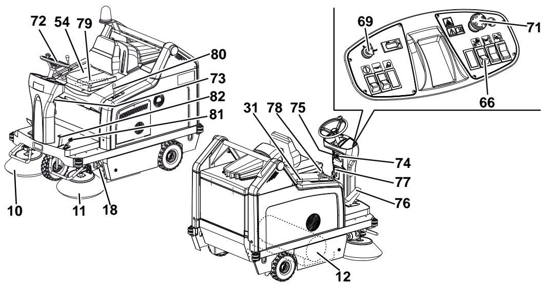
STRUCTURE DE LA MACHINE
STRUCTURE DE LA MACHINE (suite)
P100207
TABLEEAU DE BORD ET COMMANDES
ACCESSIONS / OPTIONS
REEMPLACEMENT DU BALAI CENTRAL

REMARQUE
REEMPLACEMENT DU BALAI LATERAL

REMARQUE
MANUAL PURPOSE AND CONTENTS 2
TARGET 2
HOW TO KEEP THIS MANUAL 2
DECLARATION OF CONFORMITY 2
IDENTIFICATION DATA. 2
OTHER REFERENCE MANUALS 2
SPARE PARTS AND MAINTENANCE 2
CHANGES AND IMPROVEMENTS 3
OPERATION CAPABILITIES 3
CONVENTIONS 3
UNPACKING/DELIVERY 3
SAFETY 3
SYMBOLS 3
GENERAL INSTRUCTIONS 4
MACHINE DESCRIPTION 6
MACHINE STRUCTURE 6
CONTROL PANEL 8
ACCESSIONS/OPTIONS 9
TECHNICAL DATA. 9
WIRING DIAGRAM 11
HOPPER LIFTING SYSTEM HYDRAULIC DIAGRAM 13
DRIVE SYSTEM HYDRAULIC DIAGRAM 13
USE 14
BEFORE STARTING THE MACHINE 14
STARTING AND STOPPING THE MACHINE 14
MACHINE OPERATION 15
HOPPER EMPTYING 16
AFTER USING THE MACHINE 17
PUSHING/TOWING THE MACHINE 17
WORKING LIGHT ADJUSTMENT (optional) 17
MACHINE LONG INACTIVITY 17
FIRST PERIOD OF USE 17
MAINTENANCE 18
SCHEDULED MAINTENANCE TABLE 18
MAIN BROOM HEIGHT CHECK AND ADJUSTMENT 20
MAIN BROOM REPLACEMENT 21
SIDE BROOM HEIGHT CHECK AND ADJUSTMENT 22
SIDE BROOM REPLACEMENT 23
PANEL DUST FILTER CLEANING AND INTEGRITY CHECK 24
CLOSED POCCKET FILTER CLEANING AND INTEGRITY CHECK 25
SKIRTHEIGHT AND OPERATION CHECK 26
HOPPER HYDRAULIC LIFTING SYSTEM OIL LEVEL CHECK 27
DRIVE SYSTEM OIL LEVEL CHECK 27
ENGINE OIL LEVEL CHECK 28
ENGINE OIL CHANGE 28
ENGINE AIR PRE-FILTER CLEANING AND ENGINE AIR FILTER CARTRIDGE MAINTENANCE 29
ENGINE COOLING SYSTEM CLEANING 29
SPARK SCREEN CLEANING 30
SPARK PLUG CLEANING/REPLACEMENT 30
FUSE CHECK/REPLACEMENT/RESET 30
TROUBLESHOOTING 31
SCRAPPING 32
INTRODUCTION

NOTE
The numbers in brackets refer to the components shown in Machine Description chapter.
MANUAL PURPOSE AND CONTENTS
The purpose of this Manual is to provide the operator with all necessary information to use the machine properly in a safe and autonomous way. It contains information about technical data, safety, operation, storage, maintenance, spare parts and disposal. Before performing any procedure on the machine, the operators and qualified technicians must read this Manual carefully. Contact Nilfisk Alto in case of doubts concerning the interpretation of the instructions and for any further information.
TARGET
This Manual is intended for operators and technicians qualified to perform the machine maintenance.
The operators must not perform procedures reserved for qualified technicians. Nilfisk Alto will not be answerable for damages coming from the non-observation of this prohibition.
HOW TO KEEP THIS MANUAL
The User Manual must be kept near the machine, inside an adequate case, away from liquids and other substances that can cause damage to it.
DECLARATION OF CONFORMITY
The declaration of conformity, supplied with the machine, certifies the machine conformity with the law in force.

NOTE
Two copies of the original declaration of conformity are provided together with the machine documentation.
IDENTIFICATION DATA
The machine model and serial number are marked on the plate (1).
The machine model year is written in the declaration of conformity and it is also indicated by the first two figures of the machine serial number.
The petrol engine model and serial number are marked on the plate (33).
This information is useful when ordering machine and engine spare parts. Use the following table to write down the machine and engine identification data for any further reference.
MACHINE model
MACHINE serial number
ENGINE model
ENGINE serial number
OTHER REFERENCE MANUALS
Petrol Engine Manual, supplied with the machine, to be considered an integral part of this Manual.
Moreover, the following Manuals are available:
- Spare Parts List (supplied with the machine)
Service Manual (that can be consulted at Nifisk Alto Service Centers)
SPARE PARTS AND MAINTENANCE
All necessary operating, maintenance and repair procedures must be carried out by qualified personnel or by Nilfisk Alto Service Centers. Only original spare parts and accessories must be used.
Contact Nilfisk Alto for service or to order spare parts and accessories, specifying the machine model and serial number.
CHANGES AND IMPROVEMENTS
Nilfisk Alto constantly improves its products and reserves the right to make changes and improvements at its discretion without being obliged to apply such benefits to the machines that were sold previously.
Any change and/or addition of accessory must be approved and performed by Nilfisk Alto.
This sweeper has been designed and built to clean/sweep smooth and solid floors, and to collect dust and light debris, in civil and industrial environments, under safe operation conditions by a qualified operator.
CONVENTIONS
Forward, backward, front, rear, left or right are intended with reference to the operator's position, that is to say on the driver's seat (54).
UNPACKING/DELIVERY
To unpack the machine carefully follow the instructions on the packing.
Upon delivery check that the packing and the machine were not damaged during transportation. In case of visible damages, keep the packing and have it checked by the carrier that delivered it. Call the carrier immediately to fill in a damage claim.
Check that the machine is equipped with the following features:
-
Technical documents:
-
Sweeper User Manual
- Petrol Engine Manual
-
Sweeper Spare Parts List
-
No. 1 10 A fuse
- No. 170 A fuse
SAFETY
The following symbols indicate potentially dangerous situations. Always read this information carefully and take all necessary precautions to safeguard people and property.
The operator's cooperation is essential in order to prevent injury. No accident prevention program is effective without the total cooperation of the person responsible for the machine operation. Most of the accidents that may occur in a factory, while working or moving around, are caused by failure to comply with the simplest rules for exercising prudence. A careful and prudent operator is the best guarantee against accidents and is essential for successful completion of any prevention program.
SYMBOLS

DANGER!
It indicates a dangerous situation with risk of death for the operator.

WARNING!
It indicates a potential risk of injury for people or damage to objects.

CAUTION!
It indicates a caution or a remark related to important or useful functions. Pay careful attention to the paragraphs marked by this symbol.

NOTE
It indicates a remark related to important or useful functions.

CONSULTATION
It indicates the necessity to refer to the User Manual before performing any procedure.
GENERAL INSTRUCTIONS
Specific warnings and cautions to inform about potential damages to people and machine are shown below.

DANGER!
Before performing any maintenance, repair, cleaning or replacement procedure disconnect the battery connector, remove the ignition key and engage the parking brake.
- This machine must be used by properly trained operators only. Children or disabled people cannot use this machine.
- Do not wear jewels when working near electrical components.
- Keep the batteries away from sparks, flames and incandescent material. During the normal operation explosive gases are released.
- Do not work under the lifted machine without supporting it with safety stands.
- When working under the open hood, ensure that it cannot be closed by accident.
- Do not operate the machine near toxic, dangerous, flammable and/or explosive powders, liquids or vapours. This machine is not suitable for collecting dangerous powders.
- Be careful: fuel is highly flammable.
- Do not smoke or bring naked flames in the area where the machine is refuelled or where the fuel is stored.
- Refuel outdoors or in a well-ventilated area with the engine off.
- Turn off the engine and let it cool down for a few minutes, then remove the fuel tank plug.
- Leave at least a space of 4cm in the filler to allow the fuel to expand.
After refuelling, check that the fuel tank cap is firmly closed.
- If any fuel is spilled while refuelling, clean the tank area and allow the vapours to evaporate before starting the engine.
- Do not let fuel come into contact with the skin; do not breathe fuel vapours. Keep out of reach of children.
- Do not tilt the engine too much to avoid fuel spillage.
- When moving the machine, the fuel tank must not be full and the fuel tap must be closed.
- Do not lay any object on the engine.
- Stop the petrol engine before performing any procedure on it. To avoid any incidental start, disconnect the spark plug cap or disconnect the battery negative terminal.
- Also see the GENERAL SAFETY RULES in the Petrol Engine Manual, which is to be considered an integral part of this Manual.
- When lead batteries (WET) are installed on this machine, do not tilt the machine more than 30^ from its horizontal position to not allow the highly corrosive acid to leak out of the batteries. When the machine is to be tilted to perform maintenance procedures, remove the batteries.


WARNING!
Carbon monoxide (CO) can cause brain damage or death.
The internal combustion engine of this machine can emit carbon monoxide.
Do not inhale exhaust gas fumes.
Only use indoors when adequate ventilation is provided, and with the help of an assistant.

WARNING!
- Carefully read all the instructions before performing any maintenance/repair procedure.
Take all necessary precautions to prevent hair, jewels and loose clothes from being caught by the machine moving parts. - To avoid any unauthorized use of the machine, remove the ignition key.
- Do not leave the machine unattended without being sure that it cannot move independently.
- Do not use the machine on slopes with a gradient exceeding the specifications.
- Use only brooms supplied with the machine and those specified in the User Manual. Using other brooms could reduce safety.
Before using the machine, close all doors and/or covers. - Do not use the machine in excessively dusty areas.
- Do not wash the machine with direct or pressurised water jets, or with corrosive substances.
- Do not use compressed air to clean this type of machine, except for the filters (see the relevant paragraph).
While using this machine, take care not to cause damage to other people, and children especially. - Do not put any can containing fluids on the machine.
The machine storage temperature must be between 0^ and +40^ .
The machine working temperature must be between 0^ and +40^ .
The humidity must be between 30% and 95% . - Always protect the machine against the sun, rain and bad weather, both under operation and inactivity condition. Store the machine indoors, in a dry place. This machine must be used in dry conditions, it must not be used or kept outdoors in wet conditions.
- Do not use the machine as a means of transport, or for pushing/towing.
- The machine maximum capacity, operator's weight not included, is 110kg (the weight of waste).
- Do not allow the brooms to operate while the machine is stationary to avoid damaging the floor.
In case of fire, possibly use a powder fire extinguisher, not a water one. - Do not bump into shelves or scaffoldings, especially where there is a risk of falling objects.
- Adjust the operation speed to suit the floor conditions.
- Do not use the machine on slopes with a gradient exceeding the specifications.
- This machine cannot be used on roads or public streets.
- Do not tamper with the machine safety guards.
- Follow the routine maintenance procedures scrupulously.
- Do not remove or modify the plates affixed to the machine.
In case of machine malfunctions, ensure that these are not due to lack of maintenance. Otherwise, request assistance from the authorised personnel or from an authorised Service Center.
If parts must be replaced, require ORIGINAL spare parts from an Authorised Dealer or Retailer. - To ensure machine proper and safe operation, the scheduled maintenance shown in the relevant chapter of this Manual must be performed by the authorised personnel or by an authorised Service Center.
- The machine must be disposed of properly, because of the presence of toxic-harmful materials (batteries, oils, plastics, etc.), which are subject to standards that require disposal in special centres (see the Scrapping chapter).
- If the machine is used according to the instructions, the vibrations are not dangerous. The machine vibration level is below 2.5 m/s^2 (EN 1032-96/A1-98, EN 1033).
- While the engine is running, the silencer warms up; do not touch the silencer when it is hot to avoid burns or fires.
- Running the engine with an insufficient quantity of oil can seriously damage the engine. Check the oil level with the engine off and the machine on a level surface.
- Never run the engine if the air filter is not installed, because the engine could be damaged.
- Technical service procedures on the engine must be performed by an authorised Dealer. Use only original spare parts or equivalent for the engine. Using spare parts of lower quality can seriously damage the engine.
- Also see the GENERAL SAFETY RULES in the Petrol Engine Manual, which is to be considered an integral part of this Manual.
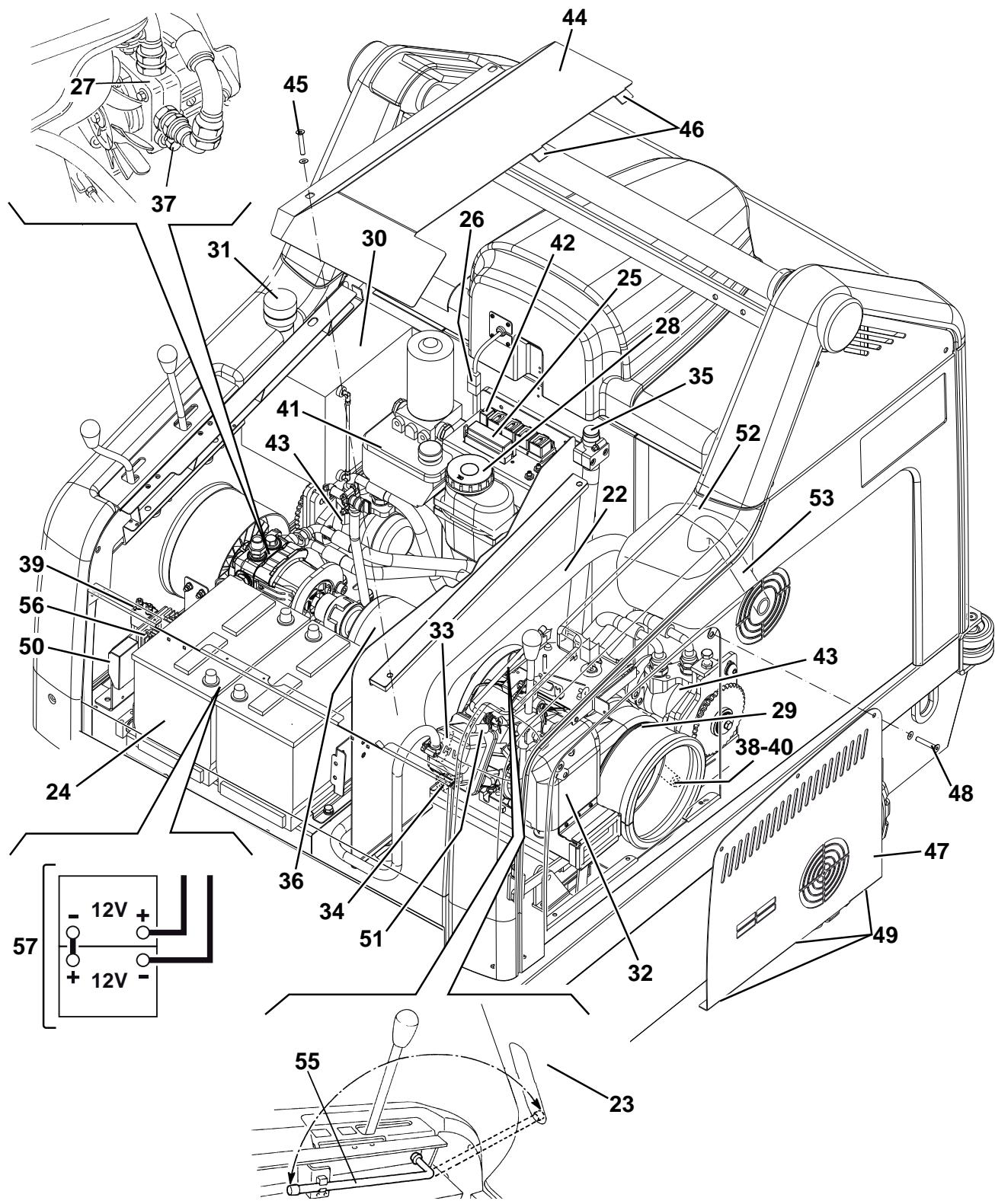
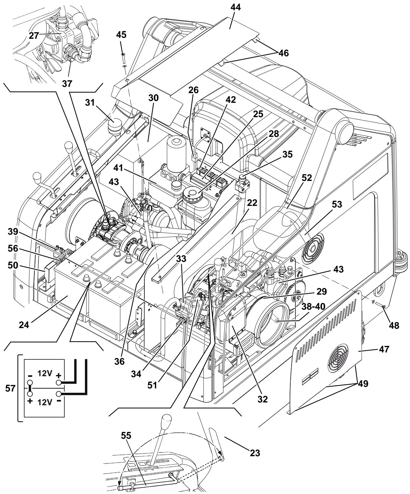
MACHINE DESCRIPTION
MACHINE STRUCTURE
- Serial number plate/technical data/conformity certification
- Flashing light (always on when the ignition key is turned to "I") (optional)
- Vacuum system motor cover
- Hopper (empty it when it is full)
- Left door (to be opened for performing maintenance procedures only)
- Left closing fastener with safety mounting screw
- Right door (for main broom removal)
- Right fastener
- Working light (optional)
- Right side broom
- Left side broom (optional)
- Main broom
- Engine compartment hood
- Rear driving wheels on fixed axle
- Front steering wheel
- Left side skirt
- Right side skirt
- Front skirt
- Rear skirt
- Dust filter container
- Working light aiming adjusting screws
- Engine exhaust manifold
- Engine compartment hood (open)
- Battery
-
Lamellar fuse box
-
Vacuum system motor connector
- Drive system pump
- Drive system oil tank
- Petrol engine
- Fuel tank
- Fuel filler cap
- Engine air filter
- Petrol engine model and serial number
- Engine oil level plug
- Engine oil filler plug
- Dynamotor
- Hydraulic pump release screw (for machine pushing/towing when the drive system is not available)
- Engine oil drain plug
- Engine start relay
- Engine oil drain hose
- Hopper hydraulic lifting system oil tank
- Hopper lifting pump drive relay
- Drive system motors
- Petrol engine guard
- Guard mounting screws
- Guard fasteners
- Left side bulkhead
- Bulkhead mounting screws
- Bulkhead fasteners
- Charging system fuse
- Spark plug
- Engine silencer
- Engine exhaust end pipe
- Driver's seat
- Hood support rod
- Diode
- Battery connection diagram
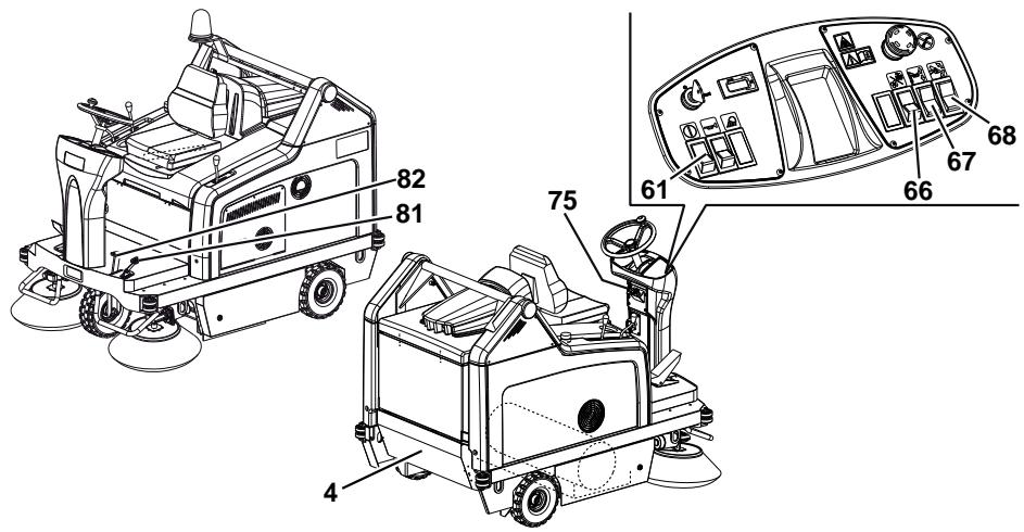
MACHINE STRUCTURE (Continues)
P100207
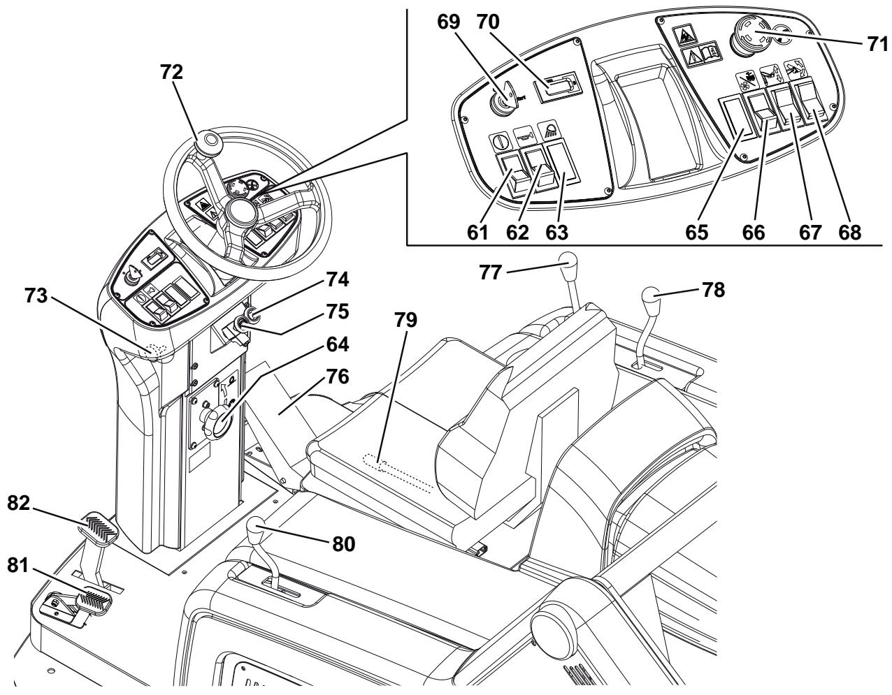
CONTROL PANEL
- Hopper lifting/lowering/dumping enabling switch
- Horn switch
- Position for working light switch (optional)
-
Main broom print adjusting knob
-
Turn it counter-clockwise to increase the broom print
-
Turn it clockwise to decrease the broom print
-
Position for optional switch
- Switch
-
(Lower position) vacuum system activation
-
(Upper position) filter shaker activation
-
Hopper lifting/lowering switch
- Hopper dumping switch
-
Ignition key
-
When turned to "0", it turns the engine off and disables all functions.
- When turned to "I", it enables all machine functions; it also turns on the flashing light.
-
When completely turned clockwise ("Start" position), it starts the engine; when the engine is running release the key, which returns to "I".
-
Hour counter
- Emergency push-button. Press it in case of emergency to stop all the machine functions.
- To deactivate the emergency push-button, turn it in the direction shown by the arrow.
- Steering wheel
- Steering wheel tilting control knob
- Choke lever
- Parking brake lock control lever. It locks the service brake (82) thus switching it to parking brake.
- Forward/reverse gear pedal
- Right side broom lifting/lowering lever
- Left side broom lifting/lowering lever (optional)
- Seat longitudinal position adjusting lever
- Main broom lifting/lowering lever
- Front skirt lifting pedal
- Service brake pedal
P100208
ACCESSIONS/OPTIONS
In addition to the standard components, the machine can be equipped with the following accessories/options, according to the machine specific use:
- Left side broom
- Main and side brooms with harder or softer bristles
- Antistatic polyester or polyester BIA C dust filter
- Closed pocket filter
- Flashing light
Working light
Non-marking skirts
Non-marking wheels - Protective roof
For further information concerning the optional accessories, contact an authorised Retailer.
TECHNICAL DATA
(*) Under normal working conditions, on a level asphalt surface.
| General | Values |
| Working width (with one side broom) | 1,054 mm |
| Working width (with two side brooms) | 1,308 mm |
| Machine length | 1,776 mm |
| Machine width (with one side broom) | 1,208 mm |
| Machine width (with two side brooms) | 1,310 mm |
| Machine maximum height (at the steering wheel) | 1,350 mm |
| Minimum distance from the floor (skirts not included) | 60 mm |
| Hopper maximum lifting height | 1,650 mm |
| Minimum/maximum dumping height | 270/1,370 mm |
| Minimum turning radius | 1,685 mm |
| Main broom size (diameter x length) | 300 x 800 mm |
| Side broom diameter | 500 mm |
| Maximum forward speed | 7 km/h |
| Maximum reverse speed | 3 km/h |
| Gradeability | 20 % |
| Hopper capacity | 130 litres |
| Maximum weight liftable by the hopper | 110 kg |
| Front axle weight in running conditions | 297 kg |
| Rear axle weight in running conditions | 446 kg |
| Machine kerb weight (with operator) | 743 kg |
| Rear wheel specific pressure on the floor | 1.2 N/mm² |
| Front wheel specific pressure on the floor | 1.1 N/mm² |
| Front steering wheel (diameter x width) | 305 x 92 mm |
| Rear driving wheel (diameter x width) | 305 x 92 mm |
| Sound pressure level at workstation (ISO 11201, ISO 4871) (LpA) | 80 dB(A) ±3 dB(A) |
| Machine output acoustic power (ISO 3744, ISO 4871) (LwA) | 98 dB(A) |
| Vibration level at the operator's arms (ISO 5349-1) (*) | < 2.5 m/s² |
| Vibration level at the operator's body (ISO 2631-1) (*) | < 0.5 m/s² |
(*) For other petrol engine data/values, see the relevant Manual.
| Petrol engine (*) | Data |
| Make | Briggs & Stratton |
| Model | Vanguard 9 HP |
| Regulated power (ISO 1585) | 6.7 kW |
| Working speed | 3,100 ±50 rpm |
| Average consumption | 1.7 litres/hour |
| Fuel tank capacity | 8.5 litres |
| Oil type | SAE 5 W 30 - SYNTHETIC API SJ |
| Dust vacuuming and filtering | Values |
| Paper dust filter 15-20 μm | 3.6 m² |
| Main broom compartment vacuum | 10.9 mm/H₂O |
| Electrical system | Values |
| Batteries | 2 x 12 V – 70 Ah |
| Vacuum system motor | 310 W, 3,000 rpm |
| Main broom motor | 500 W, 550 rpm |
| Filter shaker motor | 90 W, 5,700 rpm |
| Closed pocket filter shaker motor (optional) | 110 W, 3,000 rpm |
| Drive system | Values |
| Drive system pump | SAUER HIDRO-GEAR BDP 10A |
| Drive system pump displacement | 10.2 cm3 |
| Filling pump displacement | 1.9 cm3 |
| Maximum working pressure | 70 Bar |
| Maximum peak pressure | 145 Bar |
| Hydraulic system oil tank capacity | 0.8 litres |
| Hydraulic circuit total capacity | 1.2 litres |
| Oil type | SAE 10 W 40 |
| Hopper hydraulic lifting system | Values |
| Pump | Parker 108 AE S32 – 24 V |
| Maximum pressure | 110 Bar |
| Oil tank capacity | 0.75 litres |
| Hydraulic circuit total capacity | 1.4 litres |
| Hydraulic system oil (at ambient temperature above 10°C) | AGIP Arnica 46 (*) |

CAUTION!
If the machine is to be used at ambient temperatures below +10^ , the oil should be changed with equivalent oil having a viscosity of 32 cSt. For temperatures below 0^ , use an oil with lower viscosity.
(*) See the oil technical data and reference data tables below.
| TECHNICAL DATA | |||
| AGIP ARNICA | 46 | 32 | |
| Viscosity at 40°C | mm²/s | 45 | 32 |
| Viscosity at 100°C | mm²/s | 7.97 | 6.40 |
| Viscosity index | / | 150 | 157 |
| Flash point COC | °C | 215 | 202 |
| Pour point | °C | -36 | -36 |
| Density at 15°C | kg/l | 0.87 | 0.865 |
| REFERENCE DATA |
| ISO-L-HV |
| ISO 11158 |
| AFNOR NF E 48603 HV |
| AISE 127 |
| ATOS Tab. P 002-0/I |
| BS 4231 HSE |
| CETOP RP 91 H HV |
| COMMERCIAL HYDRAULICS |
| Danieli Standard 0.000.001 (AGIP ARNICA22,46,68) |
| EATON VICKERS I-286-S3 |
| EATON VICKERS M-2950 |
| DIN 51524 t.3 HVLP |
| LAMB LANDIS-CINCINNATI P68, P69, P70 |
| LINDE |
| PARKER HANNIFIN (DENISON) HF-0 |
| REXROTH RE 90220-1/11.02 |
| SAUER-DANFOSS 520L0463 |
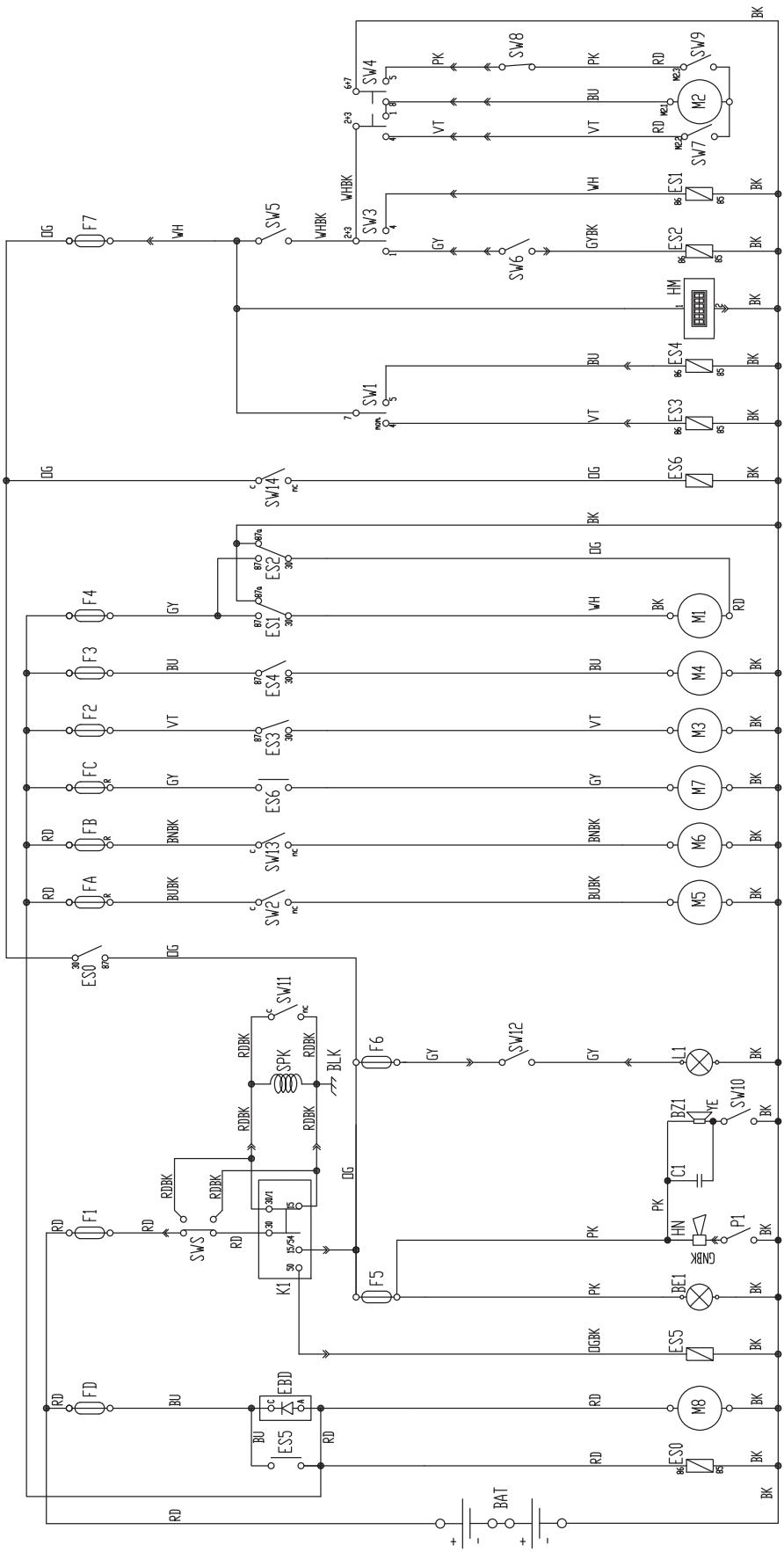
WIRING DIAGRAM
Key
| BAT | 24V battery |
| BE1 | Pivoting light (optional) |
| BLK | Engine frame |
| BZ1 | Reverse gear buzzer/horn |
| C1 | Reverse gear buzzer capacitor |
| EBD | Diode board |
| ES0 | Engine ON relay |
| ES1 | Hopper lifting pump relay |
| ES2 | Hopper lowering pump relay |
| ES3 | Filter shaker relay |
| ES4 | Vacuum system relay |
| ES5 | Start-up electromagnetic switch |
| ES6 | Main broom electromagnetic switch |
| FA | Right side broom circuit breaker (10 A) |
| FB | Left side broom circuit breaker (10 A) (optional) |
| FC | Main broom circuit breaker (30 A) |
| FD | Charging system fuse (70 A) |
| F1 | Key fuse (30 A) |
| F2 | Filter shaker fuse (30 A) |
| F3 | Vacuum system fuse (30 A) |
| F4 | Hopper lifting pump fuse (30 A) |
| F5 | Reverse gear warning buzzer and pivoting light fuse (10 A) |
| F6 | Working light fuse (10 A) |
| F7 | Hopper dumping actuator fuse (10 A) |
| HM | Hour counter |
| K1 | Ignition key |
| L1 | Working light (optional) |
| M1 | Hopper lifting pump |
| M2 | Hopper dumping actuator |
| M3 | Filter shaker motor |
| M4 | Vacuum system motor |
| M5 | Right side broom motor |
| M6 | Left side broom motor (optional) |
| M7 | Main broom motor |
| M8 | Dynamo |
| P1 | Horn switch |
| SPK | Engine spark plug |
| SW1 | Vacuum system/filter shaker switch |
| SW2 | Right side broom microswitch |
| SW3 | Hopper lifting/lowering switch |
| SW4 | Hopper dumping switch |
| SW5 | Hopper movement enabling switch |
| SW6 | Horizontal hopper microswitch |
| SW7 | Closed hopper end-of-stroke microswitch |
| SW8 | Lifted hopper microswitch |
| SW9 | Opened hopper end-of-stroke microswitch |
| SW10 | Reverse gear microswitch |
| SW11 | Opened hood microswitch |
| SW12 | Working light switch (optional) |
| SW13 | Left side broom microswitch (optional) |
| SW14 | Main broom microswitch |
| SWS | Emergency push-button |
Colour code
| BK | Black |
| BU | Blue |
| BN | Brown |
| GN | Green |
| GY | Grey |
| OG | Orange |
| PK | Pink |
| RD | Red |
| VT | Violet |
| WH | White |
| YE | Yellow |
WIRING DIAGRAM (Continues)
P100209
HOPPER LIFTING SYSTEM HYDRAULIC DIAGRAM
Key
- Oil tank
- Oil filter
- Pump
- Motor
- Lifting cylinder safety valve
- Hopper lifting cylinder
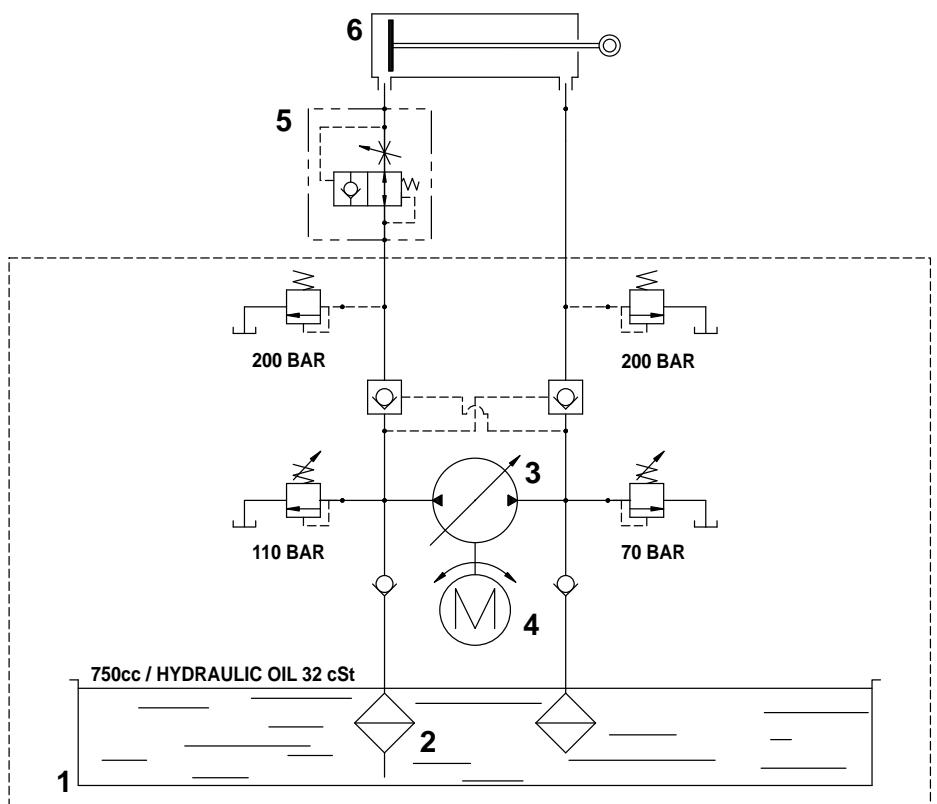
P100210
DRIVE SYSTEM HYDRAULIC DIAGRAM
Key
- Oil tank
- Oil filter
- Pump
- Motors
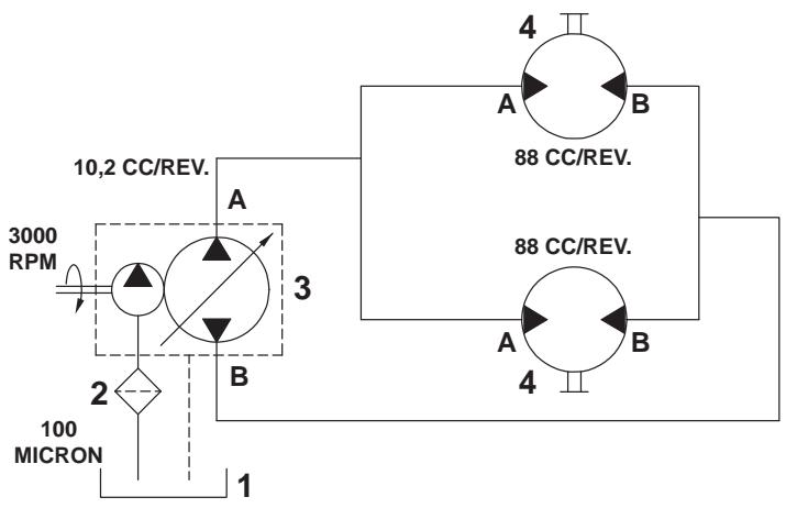
P100211
USE
P100212

WARNING!
On some points of the machine there are some adhesive plates indicating:
DANGER
WARNING
- CAUTION
CONSULTATION
While reading this Manual, the operator must pay careful attention to the symbols shown on the plates.
Do not cover these plates for any reason and immediately replace them if they are damaged.
BEFORE STARTING THE MACHINE
- If it is necessary, unscrew the plug (31) and refuel the machine.

WARNING!
Leave at least a space of 4cm in the filler to allow the fuel to expand.
- Make sure that there are no open doors/hoods and that the machine is in normal operating conditions.
- If the machine has not been used after being transported, check that all the blocks used for the transportation have been removed.
STARTING AND STOPPING THE MACHINE
Starting the machine
- Sit on the driver's seat (54), then adjust the seat in order to reach a comfortable position by using the lever (79).
- Unlock the knob (73) by pulling it, then tilt the steering wheel (72) in order to reach a comfortable position. After the adjustment, release the knob (73) and slightly move the steering wheel to lock it.
- Engage the parking brake with the pedal (82) and the lever (75).
- Lift the main and side brooms with the levers (80), (77), (78).
- Pull the engine choke lever (74).

NOTE
Do not use the choke lever if the engine is hot and if the air temperature is sufficiently high.
- Start the engine with the ignition key (69). When the engine starts, release the ignition key immediately.

WARNING!
When starting the engine with the ignition key (69) do not press the drive pedal (76).
- After the ignition, let the engine run for a few seconds, then release the choke lever (74).
- Let the engine warm up for a few minutes.
- Disengage the parking brake by pressing the pedal (82) and by disengaging the lever (75).
- Drive the machine to the working area, by keeping the hands on the steering wheel (72) and pressing the pedal (76) on the front side to move forward and on the rear side to move backward.
The drive speed can be adjusted from zero to maximum speed by increasing the pressure on the pedal.
- Lower the main broom with the lever (80), then turn on the vacuum system by pressing the lower part of the switch (66).
- Lower the right side broom with the lever (77).
- If equipped, lower the left side broom with the lever (78).

NOTE
The brooms (10, 11, 12) can be lowered and lifted even when the machine is moving.
The brooms do not turn when they are lifted.
- Start sweeping by turning the steering wheel (72) and moving the machine forward by pressing the pedal (76).
Stopping the machine
- To stop the machine, release the pedal (76).
To stop the machine quickly, also press the service brake pedal (82).
In case of emergency, press the emergency push-button (71) to immediately stop the machine.
To deactivate the emergency push-button (71), turn it in the direction shown by the arrow.
- Lift the main and side brooms with the levers (80), (77), (78).
- Turn off the vacuum system with the switch (66).
- Turn off the machine by turning the ignition key (69) to "0", then remove it.
- Engage the parking brake by pressing the pedal (82), then engage the brake lock control lever (75).
MACHINE OPERATION
- Avoid stopping for a long time with the machine in the same position and the brooms turning: this could create unwanted marks on the floor.
- To collect light and bulky waste materials, lift the front skirt (18) by pressing the pedal (81); take into consideration that the machine vacuum capability is reduced when the front skirt is lifted.

WARNING!
When operating on wet floors, it is essential to turn off the vacuum system by pressing the switch (66) to prevent the dust filter from being damaged.
- For machine proper operation, the dust filter must be as clean as possible. To clean the dust filter while sweeping, turn on the filter shaker for a short interval by pressing the upper part of the switch (66), then turn on the vacuum system by pressing the lower part of the switch (66).
While working, repeat the procedure every 10 minutes on average (depending on the dustiness of the area to be cleaned).

NOTE
This procedure can also be performed when the machine is moving.

CAUTION!
When the dust filter is clogged and/or the hopper is full, the machine cannot collect dust and debris anymore.
- The hopper (4) should be dumped after each working period and whenever it is full (see the procedure in the next paragraph).

CAUTION!
The engine is equipped with a warning system to prevent damages to the engine itself in case the oil quantity in the carter is insufficient. Before the oil level goes below the safety limit, the warning system automatically stops the engine.
HOPPER EMPTYING
P100213

WARNING!
Always empty the hopper when the engine is running.
Do not dump the hopper with the engine turned off, otherwise the battery discharges.
- The hopper maximum dumping height is 1,370 mm (see Fig. 2).
-
To empty it, move the machine close to the dustbin and proceed as follows:
-
Lift the side and main brooms.
- Turn off the vacuum system with the switch (66).
- Turn on the filter shaker by pressing the upper part of the switch (66).

WARNING!
Always perform this procedure on a level floor to avoid machine unbalance.

WARNING!
When lifting and emptying the hopper (4), engage the parking brake with the pedal (82) and the lever (75).
- Keep people away from the machine and from the hopper (4) especially.
- Press the enabling switch (61) while pressing the hopper lifting switch (67) to lift the hopper (A, Fig. 1) up to the desired position.
- Press the enabling switch (61) and the dumping switch (68) of the hopper (B, Fig. 2) at the same time, and discharge all the debris in the dustbin (A).

CAUTION!
The hopper (B, Fig. 2) can be dumped only when lifted at a minimum height of 270~mm .
- Press the enabling switch (61) and the hopper dumping switch (68) at the same time to bring the hopper back to horizontal position.
- To lower the hopper, press the hopper enabling switch (61) while pressing the hopper lowering switch (67).

CAUTION!
The hopper cannot be lowered if it is not brought to horizontal position first.
- The machine is ready to start sweeping again.
Figure 1
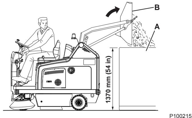
Figure 2
AFTER USING THE MACHINE
After working, before leaving the machine:
- Turn on the filter shaker shortly, by pressing the upper part of the switch (66).
Empty the hopper (4) (see the procedure in the previous paragraph). - Lift the main broom with the lever (80).
- Lift the side brooms with the levers (77) and (78).
- Turn off the machine by turning the ignition key (69) to "0", then remove it.
- Engage the parking brake by pressing the pedal (82), then engage the brake lock control lever (75).
To easily push/tow the machine when it is off, proceed as follows:
Turn off the machine by turning the ignition key (69) to "0".
- Open the hood (23) and fasten it with the support rod (55).
- Remove the screw (37).
- Remove the support rod (55) and close the hood (23).
Push or tow the machine.
After pushing/towing the machine, install the screw (37).
WORKING LIGHT ADJUSTMENT (optional)
If necessary, adjust the working light beam aiming (9) with the screws (21).
MACHINE LONG INACTIVITY
If the machine is not going to be used for more than 30 days, proceed as follows:
- Check that the machine storage area is dry and clean.
- Disconnect the negative connector (-) of the batteries (24).
- Handle the petrol engine (29) as shown in the relevant Manual.
FIRST PERIOD OF USE
After the first 5 hours perform the following procedures:
- Check the fastening and connecting parts for proper tightening; check the visible parts for integrity and leakages.
- Change the engine oil (see the procedure in Maintenance chapter).
MAINTENANCE
The lifespan of the machine and its maximum operating safety are ensured by correct and regular maintenance.
The following table provides the scheduled maintenance. The intervals shown may vary according to particular working conditions, which are to be defined by the person in charge of the maintenance.
All scheduled or extraordinary maintenance procedures must be performed by qualified personnel, or by an authorised Service Center.
This Manual describes only the easiest and most common maintenance procedures.
For other maintenance procedures shown in the Scheduled Maintenance Table, refer to the Service Manual that can be consulted at any Service Center.

WARNING!
To perform maintenance procedures, the machine must be off, the ignition key removed, and, if necessary, the batteries must be disconnected.
Before performing any maintenance procedure, carefully read the instructions shown in Safety chapter.
SCHEDULED MAINTENANCE TABLE
| Procedure | Upon delivery | After the first 5 hours | Every 10 hours or before use | Every 25 hours | Every 50 hours | Every 100 hours | Every 200 hours | Every year |
| Engine oil level check | ||||||||
| Battery fluid level check | ||||||||
| Side and main broom height check | ||||||||
| Engine air pre-filter cleaning | (3) | |||||||
| Frame dust filter cleaning and integrity check | ||||||||
| Hopper hydraulic lifting system oil level check | ||||||||
| Drive system oil level check | ||||||||
| Skirt height and operation check | ||||||||
| Fuel filter cleaning | ||||||||
| Spark screen check and cleaning | ||||||||
| Engine oil change | (2) | |||||||
| Filter shaker operation check | (1) | |||||||
| Brake adjustment | (1) | |||||||
| Driving wheel chain cleaning and tension check | (1) | |||||||
| Closed pocket filter cleaning and integrity check | ||||||||
| Vacuum system efficiency check | (1) | |||||||
| Driving belt visual inspection | (1) | (1) | ||||||
| Spark plug check/cleaning | ||||||||
| Nut and screw tightening check | (1) | (1) | ||||||
| Steering chain cleaning and tension check | (1) | |||||||
| Safety system operation check | (1) | |||||||
| Engine speed check | (1) | |||||||
| Engine air filter element maintenance | (3) | |||||||
| Spark plug replacement | (2) | |||||||
| Engine cooling system cleaning | (2) | |||||||
| Driving belt replacement | (1) (5) | |||||||
| Hopper gasket integrity check | (1) | |||||||
| Lifted hopper control microswitch adjustment check | (1) | |||||||
| Horizontal hopper control microswitch adjustment check | (1) | |||||||
| Valve clearance check/adjustment | (4) | |||||||
| Hopper hydraulic lifting system and drive system oil change | (1) (6) |
(1) For the relevant procedure, see the Service Manual.
(2) Or every year.
(3) Or more often in dusty areas.
(4) Maintenance procedures to be performed by an authorised Briggs & Stratton dealer.
(5) If the person in charge for the maintenance considers it necessary.
(6) Change the hydraulic system oil for the first time after 500 hours, then every 2,000 hours or every year.
MAIN BROOM HEIGHT CHECK AND ADJUSTMENT

NOTE
Brooms with harder or softer bristles are available. This procedure is applicable to all types of brooms.
-
Check the main broom distance from the floor as shown below:
-
Drive the machine on a level floor.
- Keep the machine stationary, lower the main broom and turn it on for a few seconds.
- Stop and lift the main broom, then move the machine and switch it off.
- Check that the main broom print (A, Fig. 3), along its length, is 2 to 4 cm wide.
If the print (A) is not within specifications, adjust the main broom height according to the following procedure.
-
Turn the knob (A, Fig. 4) as shown below:
-
To increase the print width, turn the knob counterclockwise
- To decrease the print width, lift the broom with the lever (80) and turn the knob clockwise.

NOTE
The knob can be used both to adjust the print and to adjust the broom according to the bristle wear.
- Perform step 1 again to check the proper adjustment of the main broom height.
- When the broom is too worn to be adjusted, replace it as shown in the next paragraph.

NOTE
If it is not possible to adjust the print (A, Fig. 3) properly, because the pressure on the floor at the ends of the broom is different, refer to the Service Manual.
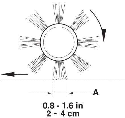
P100216
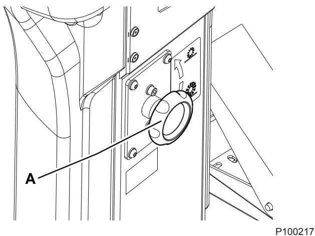
Figure 3
Figure 4
MAIN BROOM REPLACEMENT

NOTE
Brooms with harder or softer bristles are available. This procedure is applicable to all types of brooms.

WARNING!
It is advisable to wear protective gloves when replacing the main broom because there can be sharp debris between the bristles.
- Drive the machine on a level floor and engage the parking brake with the pedal (82) and the lever (75).
- Turn the ignition key (69) to "0" and remove it.
- Release the fastener (8) and open the right door (7).
- Unscrew and remove the knobs (A, Fig. 5).
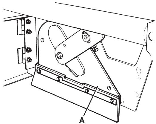
- Remove the main broom compartment cover (A, Fig. 6).
- Remove the main broom (A, Fig. 7).
- Check that the drive hub (A, Fig. 8) is free from dirt or foreign materials (ropes, rags, etc.) accidentally rolled up.
- The new main broom must be installed with the bristles rows (B, Fig. 8) bent as shown in the figure.
- Install the new main broom (C, Fig. 8) and ensure that the mesh (D) correctly fits into the relevant drive hub (A).
- Install the main broom compartment cover (A, Fig. 6) and tighten the knobs (A, Fig. 5).
- Close the right door (7) and engage the fastener (8).
- Check and adjust the main broom height as shown in the previous paragraph.
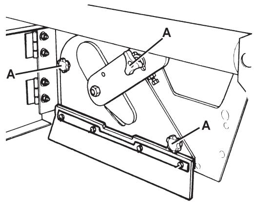
P100218
Figure 5
P100219
Figure 6
P100220
Figure 7
Figure 8
P100221
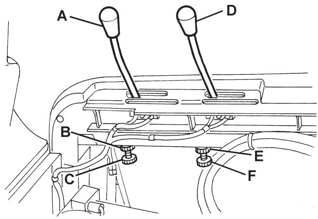
SIDE BROOM HEIGHT CHECK AND ADJUSTMENT

NOTE
Brooms with harder or softer bristles are available. This procedure is applicable to all types of brooms.
-
Check the side broom distance from the floor, according to the following procedure:
-
Drive the machine on a level floor.
- Keep the machine stationary, lower the side brooms and turn them on for a few seconds.
- Stop and lift the side brooms, then move the machine.
- Check that the side broom prints are as shown in the figure (A and B, Fig. 9).
If the print is not within specifications, adjust the side broom height according to the following procedure.
- Engage the parking brake with the pedal (82) and the lever (75).
- Turn the ignition key (69) to "0".
- Open the hood (23) and fasten it with the support rod (55).
- For the right side broom, operate on the idle gear of the lever (A, Fig. 10), by loosening the ring nut (B) and by adjusting the adjuster (C) until the correct print (A, Fig. 9) is achieved. Then fasten the adjuster with the ring nut (B, Fig. 10).
For the left side broom, operate on the idle gear of the lever (D, Fig. 10), by loosening the ring nut (E) and by adjusting the adjuster (F) until the correct print (B, Fig. 9) is achieved. Then fasten the adjuster with the ring nut (E, Fig. 10).
- Perform step 1 again to check the proper adjustment of the side broom height.
- When the broom is too worn to be adjusted, replace it as shown in the next paragraph.

NOTE
If necessary, the side broom tilting can be adjusted too (see the procedure in the Service Manual).
P100222
Figure 9
Figure 10
P100223
SIDE BROOM REPLACEMENT

NOTE
Brooms with harder or softer bristles are available. This procedure is applicable to all types of brooms.

WARNING!
It is advisable to wear protective gloves when replacing the side broom because there can be sharp debris between the bristles.
- Drive the machine on a level floor and engage the parking brake with the pedal (82) and the lever (75).
- Turn the ignition key (69) to "0".
- Lift the side broom which has to be removed, with the lever (77) or (78).
- Remove the screw (A, Fig. 11) inside the side broom, then remove the side broom (B) with the hub (B) by disengaging it from the shaft (C).
Recover the key (D) and the washer (E).
- At the workbench, remove the two screws (F, Fig. 11) and separate the broom (H) from the hub (G).
- Install the new side broom (H, Fig. 11) onto the hub (G), and tighten the screws (F).
- Install the key (D), then install the new side broom with the hub (B, Fig. 11). Install the washer (E) and tighten the screw (A).
- Check and adjust the side broom height as shown in the previous paragraph.
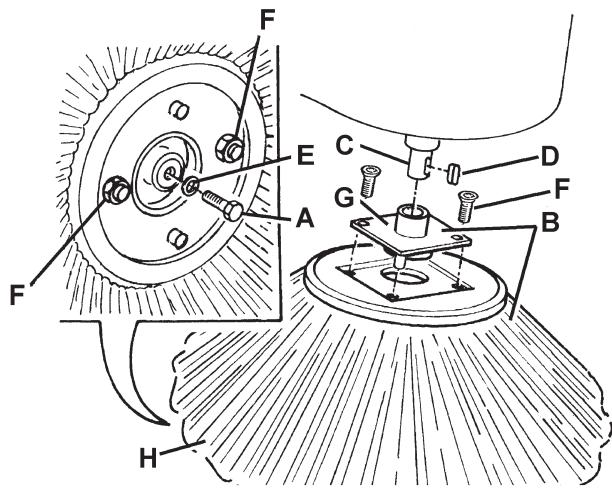
Figure 11
P100224
PANEL DUST FILTER CLEANING AND INTEGRITY CHECK

NOTE
Besides the standard paper filter, polyester filters are also available. The following procedure is applicable to each type of filter.
- Drive the machine on a level floor and engage the parking brake with the pedal (82) and the lever (75).
- Turn the ignition key (69) to "0".
- Open the hood (23) and fasten it with the support rod (55).
- Disconnect the vacuum system motor connector (26).
- Release the fasteners (A, Fig. 12) and remove the vacuum system cover (B).
- Disconnect the connector (A, Fig. 13) from the filter shaker.
- Unscrew the knobs (B, Fig. 13) and remove the filter mounting frame (C).
- Remove the dust filter (D, Fig. 13).
- In an outdoor area, clean the filter by shaking it on a level and clean surface, tapping the side (A, Fig. 14) opposite to the wire gauze (B).
Complete the cleaning procedure by using compressed air (C) at maximum 6 Bar, blowing only from the side protected by the wire gauze (B), at a minimum distance of 30~cm .
Check the filter body for tears.
According to the filter type, observe the following cautions:
- Paper filter (standard): Do not use water or detergents to clean it, otherwise it can be damaged.
-
Polyester filter (optional): For a better cleaning, it is allowed to wash the filter with water and non-lathering detergents. This provides better quality cleaning but reduces the life of the filter, which will have to be replaced more frequently. The use of inadequate detergents can damage the filter.
-
If necessary, clean the filter compartment rubber gasket (A, Fig. 15) along its perimeter and check it for integrity. If necessary, replace it.
- Assemble the components in the reverse order of disassembly, and note the following:
Install the filter with the wire gauze (B, Fig. 14) facing upwards.
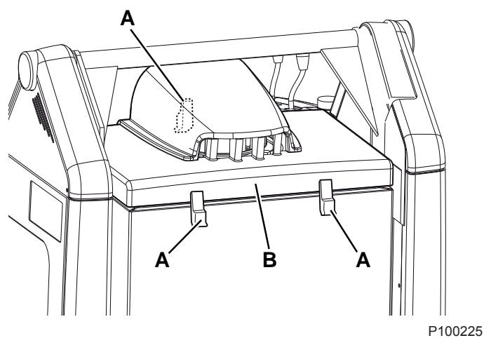
Figure 12
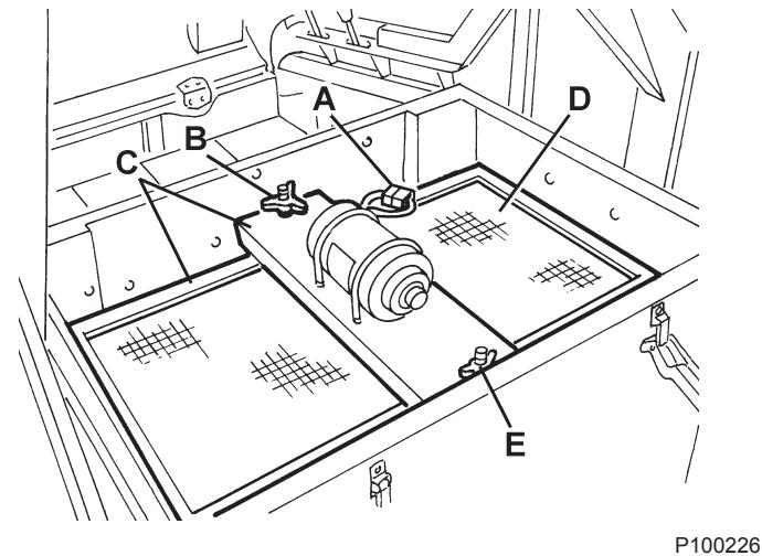
Figure 13
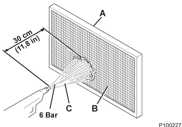
Figure 14
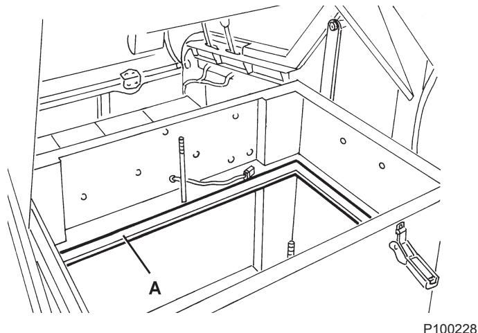
Figure 15
CLOSED POUCHET FILTER CLEANING AND INTEGRITY CHECK

NOTE
The polyester closed pocket filters are normally kept clean by using the filter shaker supplied with the machine.
If necessary, they can be cleaned externally according to the following procedure.
When the filtering surfaces are worn, the filter must be replaced.
- Drive the machine on a level floor and engage the parking brake with the pedal (82) and the lever (75).
- Turn the ignition key (69) to "0".
- Open the hood (23) and fasten it with the support rod (55).
- Disconnect the vacuum system motor connector (26).
- Release the fasteners (A, Fig. 12) and remove the vacuum system cover (B).
- Unscrew the knobs (A, Fig. 16) and remove the brackets (B).
- Disconnect the filter shaker connector (B, Fig. 17) and remove the dust filter (A).
- In an outdoor area, and with the operator wearing suitable equipment (gloves, mask, glasses), remove the polyester filtering surface, according to the following procedure.
- Remove the filter shaker motor (A, Fig. 18) by unscrewing the two mounting screws.
- Open the filter shaker motor support unit (B, Fig. 18) completely, and release the filtering pocket tension rods (C).
- Remove all the filtering pocket tension rods (D, Fig. 18).
- Open the upper retaining cord (E, Fig. 18) of the closed pocket filter to remove it from the upper frame (F).
- Remove the inner pocket separator (G, Fig. 18).
- Clean the polyester fibber surface (H, Fig. 18) from the dirty side (by using an external vacuum cleaner), spreading it out completely or cleaning pocket by pocket. At the same time, clean both surfaces of the pocket separator (G, Fig. 18), thus removing anything deposited on them. Check the filtering surface for tears and replace it if necessary. It is also possible to use compressed air (maximum 6 Bar), blowing the air from the clean side towards the dirty side.

WARNING!
Do not wash the filter with water. The polyester fibber can shrink and become unusable.
- If necessary, clean the filter compartment rubber gasket (C, Fig. 17) along its perimeter and check it for integrity. If necessary, replace it.
- Assemble the components in the reverse order of disassembly.
P100229
Figure 16
P100230
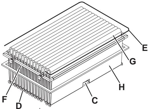
Figure 17
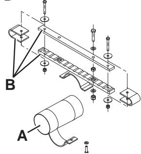
Figure 18
P100231
Preliminary procedure
- Empty the hopper (as shown in the User Manual), because the weight of the waste inside the hopper can affect the skirt height check.
- Drive the machine on a level floor that is suitable for checking the skirt height.
- Engage the parking brake with the pedal (82) and the lever (75).
- Turn the ignition key (69) to "0".
Side skirt check
- Release the fasteners (8 and 6), then open the right and left door (7 and 5).
- Check the side skirts (A, Fig. 19) for integrity. Replace the skirts when they have cuts (A, Fig. 20) larger than 20mm or cracks/tears (B) larger than 10mm (for skirt replacement, refer to the Service Manual).
- Check that the distance from the floor of the side skirts (A, Fig. 19) is within 0 - 3mm (see Fig. 21).
If necessary, loosen the screws (B, Fig. 19) and adjust the skirt position. Then tighten the screws (B).
Front and rear skirt check
- Remove the main broom as shown in the relevant paragraph.
- Check the front (A, Fig. 22) and rear skirts (B) for integrity. Replace the skirts when they have cuts (A, Fig. 20) larger than 20mm or cracks/tears (B) larger than 10mm (for skirt replacement, refer to the Service Manual).
- Check that the front (A, Fig. 22) and rear skirts (B) slightly rub on the floor (see Fig. 24).
If necessary, loosen the screws (C, Fig. 22) and adjust the skirt position. Then tighten the screws (C).
- Press the front skirt lifting pedal (81) completely, and check that the front skirt lifts 5 cm approximately. Release the pedal and check that the skirt does not remain in an intermediate position but returns to its initial position. If necessary, adjust the skirt lifting cable (A, Fig. 23) with the adjuster (B) on the left front side of the skirt (for the front skirt control cable replacement, see the Service Manual).
Reset
- Assemble the components in the reverse order of disassembly.
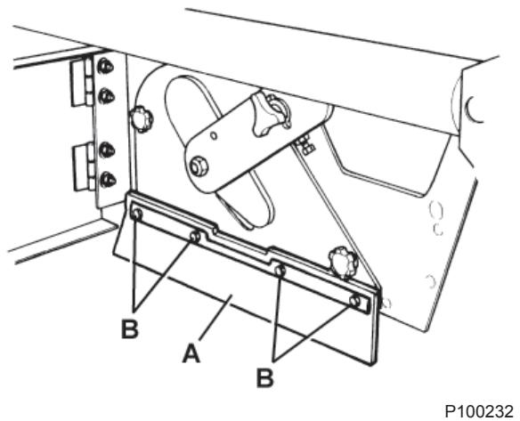
Figure 19

Figure 20
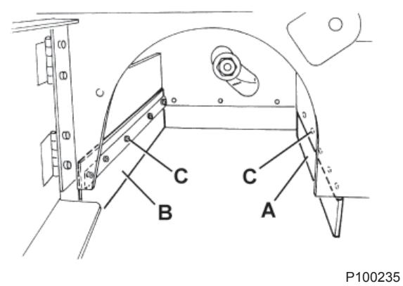
Figure 22
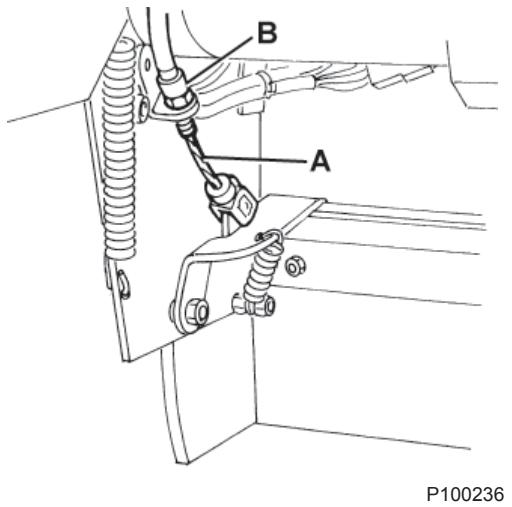
Figure 23
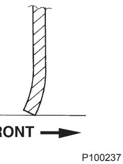
Figure 24
HOPPER HYDRAULIC LIFTING SYSTEM OIL LEVEL CHECK

WARNING!
This procedure must be performed with the hopper (4) fully retracted (as shown in the figure).
- Engage the parking brake with the pedal (82) and the lever (75).
- Turn the ignition key (69) to "0".
- Open the hood (23) and fasten it with the support rod (55).
- Check that the oil level in the tank (41) is between the minimum (MIN) and maximum (MAX) marks shown in Fig. 25.
- If necessary, add oil through the plug (A, Fig. 25), using the oil specified in Technical Data paragraph.
- Remove the support rod (55) and close the hood (23).
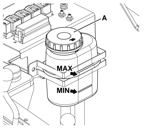
DRIVE SYSTEM OIL LEVEL CHECK
- Engage the parking brake with the pedal (82) and the lever (75).
- Turn the ignition key (69) to "0".
- Open the hood (23) and fasten it with the support rod (55).
- Check that the oil level in the tank (28) is between the minimum (MIN) and maximum (MAX) marks shown in Fig. 26.
- If necessary, add engine oil SAE 10 W 40 through the plug (A, Fig. 26).
- Remove the support rod (55) and close the hood (23).
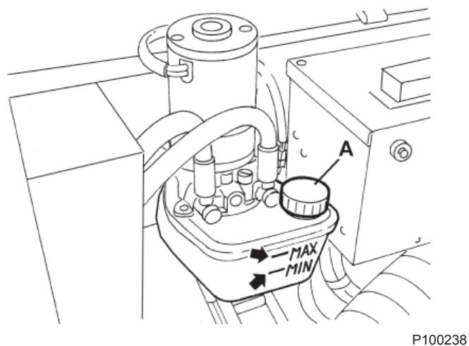
Figure 25
Figure 26
P100239
ENGINE OIL LEVEL CHECK
- Drive the machine on a level floor.
- Engage the parking brake with the pedal (82) and the lever (75).
- Turn the ignition key (69) to "0".
- Open the hood (23) and fasten it with the support rod (55).
- Remove the screws (45), then disengage the fasteners (46) to remove the engine guard (44).
- Unscrew the engine oil level plug (34) and clean it with a clean cloth. Fully screw down the oil level plug (34) then unscrew it again after a few seconds, and check that the oil level is between the ADD (minimum level) and FULL (maximum level) marks (A, Fig. 27).
If the oil level is lower than the minimum mark (ADD), remove the filler plug (35) and top up.

CAUTION!
Top up using the same type of oil as that in the engine.
- Install the filler plug (35) and check the oil level as shown in the previous steps.
Perform steps 3 to 5 in the reverse order.
Figure 27
P100240
ENGINE OIL CHANGE

CAUTION!
It is advisable to change the oil when the engine is still hot, to make the oil downflow easier.
- Drive the machine on a level floor.
- Engage the parking brake with the pedal (82) and the lever (75).
- Turn the ignition key (69) to "0".
- Remove the screws (48), then disengage the fasteners (49) to remove the left side bulkhead (47).
- Open the hood (23) and fasten it with the support rod (55).
- Remove the screws (45), then disengage the fasteners (49) to remove the engine guard (44).
- Remove the engine oil filler plug (35).
- Remove the engine oil drain plug (38) from the hose (40) and drain the oil into a suitable container.

CAUTION!
The discharged engine oil must be disposed of properly according to the Law in force.
- Install the engine oil drain plug (38) to the hose (40).
- Top up with new oil through the filler (35).

NOTE
As for engine oil type and quantity, see the Technical Data chapter and the Petrol Engine Manual.
- Install the filler plug (35).
- After a few seconds, unscrew the engine oil level plug (34) again and check that the oil level is between the ADD (minimum level) and FULL (maximum level) marks (A, Fig. 27).
If necessary top up. Screw down the oil level plug (34).
- Perform steps 4 to 6 in the reverse order.
ENGINE AIR PRE-FILTER CLEANING AND ENGINE AIR FILTER CARTRIDGE MAINTENANCE
- Drive the machine on a level floor.
- Engage the parking brake with the pedal (82) and the lever (75).
- Turn the ignition key (69) to "0".
- Remove the screws (48), then disengage the fasteners (49) to remove the left side bulkhead (47).
- Clean the engine air pre-filter and/or service the air filter element (A, Fig. 28), as shown in the Petrol Engine Manual.
- Install the left side bulkhead (47).
ENGINE COOLING SYSTEM CLEANING
- Drive the machine on a level floor.
- Engage the parking brake with the pedal (82) and the lever (75).
- Turn the ignition key (69) to "0".
- Remove the screws (48), then disengage the fasteners (49) to remove the left side bulkhead (47).
- Remove the screws (B, Fig. 28), then remove the air deflector (C).
- Clean the engine cooling system (D), as shown in the Petrol Engine Manual.
- Install the left side bulkhead (47).
Figure 28
P100241
SPARK SCREEN CLEANING
- Drive the machine on a level floor.
- Engage the parking brake with the pedal (82) and the lever (75).
- Turn the ignition key (69) to "0".
- Remove the screws (48), then disengage the fasteners (49) to remove the left side bulkhead (47).
- Remove the mounting screws, then remove the engine exhaust end pipe (53).
- Clean the spark screen as shown in the Petrol Engine Manual.
- Perform steps 4 and 5 in the reverse order.
SPARK PLUG CLEANING/REPLACEMENT
- Drive the machine on a level floor.
- Engage the parking brake with the pedal (82) and the lever (75).
- Turn the ignition key (69) to "0".
- Open the hood (23) and fasten it with the support rod (55).
- Remove the screws (45), then disengage the fasteners (46) to remove the engine guard (44).
- Clean/replace the spark plug (51), as shown in the Petrol Engine Manual.
- Perform steps 4 and 5 in the reverse order.
FUSE CHECK/REPLACEMENT/RESET
- Drive the machine on a level floor and engage the parking brake with the pedal (82) and the lever (75).
- Turn the ignition key (69) to "0".
- Open the hood (23) and fasten it with the support rod (55).
Lamellar fuse check/replacement
- Remove the cover (A, Fig. 29) and mark the positions of the fuses shown on the adhesive.
- Check/replace the relevant fuse among the following (B):
F1 fuse (30 A): Key circuit
F2 fuse (30 A): Filter shaker
F3 fuse (30 A): Vacuum system
F4 fuse (30 A): Hydraulic pump
F5 fuse (10 A): Flashing light (optional)
F6 fuse (10 A): Working light (optional)
F7 fuse (10 A): Hopper actuator
F8 fuse (30 A): Spare fuse
Charging system fuse check/replacement
- Check/replace the FD (70 A) charging system fuse (50).
Circuit breaker check
- Check for deactivation of one of the following fuses, then reset it after the relevant motor has cooled down:
FA fuse (C, Fig. 29): Right side broom motor circuit breaker
- FB fuse (D): Left side broom motor circuit breaker (optional)
FC fuse (E): Main broom motor circuit breaker
Assembly
- Assemble the components in the reverse order of disassembly.
Figure 29
P100249
TROUBLESHOOTING
| Trouble | Possible cause | Remedy |
| The engine does not start with the ignition key. | The hood (13) is not properly closed. | Close the hood properly. |
| The engine oil level is too low. | Check that the engine oil level is within the limits. (*) | |
| The machine has run out of fuel. | Check that there is fuel in the tank (30). | |
| The fuel does not reach the carburettor. | Check that the fuel reaches the carburettor and that the fuel filter is clean. (*) | |
| The spark plug does not produce a spark. | Check that the spark plug produces a spark. (*) | |
| The engine stops during operation. | The engine oil level is too low. | Check that the engine oil level is within the limits. (*) |
| The machine is running out of fuel. | Check that there is fuel in the tank (30). | |
| The fuel filter is dirty. | Clean the fuel filter. (*) | |
| The machine collects little debris/dust. | The vacuum system is turned off. | Turn on the vacuum system with the switch (56). |
| The dust filter is clogged. | Clean the dust filter. | |
| The hopper is full. | Empty the hopper (4). | |
| The skirts are not integral or not properly adjusted. | Check the skirts (16, 17, 18, 19) for integrity and proper adjustment. | |
| The broom height is not properly adjusted. | Adjust the height of the brooms (10, 11, 12). | |
| When pressing the drive pedal, the machine does not move, or it moves slowly. | The parking brake is engaged. | Check that the parking brake (84 and 76) has been released. |
| The hydraulic system oil level is incorrect. | Check the hydraulic system oil level in the tank (28). | |
| The centrifugal pulley does not operate properly. | Check that the centrifugal pulley (petrol engine-drive pump coupling joint) operates properly. (***) | |
| The drive pedal is not properly adjusted. | Adjust the drive pedal. **) | |
| The hopper does not lift. | The hydraulic system oil level is incorrect. | Check the hydraulic system oil level in the tank (41). |
| The F4 or F7 fuse is open. | Replace the fuse. | |
| The hopper does not dump. | The F7 fuse is open. | Replace the fuse. |
| The hopper is not lifted enough. | Lift the hopper over 300 mm. | |
| The hopper does not lower. | The hopper has not returned to horizontal position. | Turn the hopper to horizontal position. |
| In case of particular weather conditions, the hydraulic system oil is slow in flowing through the safety valve. | Wait a few moments to let the hydraulic system oil flow. | |
| When the engine compartment hood (13) is open, the engine keeps running. | The hood safety microswitch does not work. | Repair the microswitch.**) |
() For the relevant procedure, see the Petrol Engine Manual.
(*) Procedure to be performed by Nilfisk Alto Service Center.
For further information, refer to the Service Manual, available at any Nilfisk Alto Service Center.
SCRAPPING
Have the machine scrapped by a qualified scrapper.
Before scrapping the machine, remove and separate the following materials, which must be disposed of properly according to the Law in force:
Batteries
- Polyester dust filter
- Main and side brooms
Engine oil
Hydraulic system oil
Hydraulic system oil filter
- Plastic hoses and components
- Electrical and electronic components (*)
(*) Refer to the nearest Nilfisk Alto Center especially when scrapping electrical and electronic components.
INHOUDSOPGAVE
INLEIDING 2
DOEL EN INHOUD VAN DEZE HANDLEIDING 2
BETREFFENDE PERSONEN 2
OPBERGEN VAN DE HANDLEIDING 2
CONFORMITEITSVERKLARING 2
IDENTIFICATIEGEGEVENS 2
ANDERE GEBRUKERSHANDLEIDENGIN 2
VERVANGINGSONDERDELEN EN ONDERHOUD 2
MODIFICATIES EN VERBETERINGEN 3
BEDRIJFSCAPACITEIT 3
ALGEMENE OPMERKINGEN 3
VERPAKKING VERWIJDEREN/AFLEVERING 3
VEILIGHEID 3
GEBRUIKTE SYMBOLEN 3
ALGEMENE INSTRUCTIONS 4
BESCHRIJVING VAN DE MACHINE 6
BOUW VAN DE MACHINE 6
BEDIENINGSPANEEL EN KNOPPEN 8
ACCESSIONS / OPTIES 9
TECHNISCHE EIGENSCHAPPEN 9
ELEKTRISCH SCHEMA 11
HYDRAULISCH SCHEMA VAN HET HEFSYSTEEM VOOR DE AFVALCONTAINER 13
HYDRAULISCH SCHEMA VAN DE AANDRIJVING 13
GEBRUIK 14
VOOR HET STARTEN VAN DE MACHINE 14
DE MACHINE STARTEN EN STOPPEN 14
MACHINE IN BEDRIJF 15
DE AFVALCONTAINER LEGEN 16
NA GEBRUIK VAN DE MACHINE 17
DUW-/TREKBEWEGING VAN DE MACHINE 17
DE BEDRIJFSVERLICHTING AFSTELLLEN (optioneel) 17
LANGE PERIODE VAN STILLSTAND 17
EERSTE GEBRUIKSPERIODE 17
ONDERHOUD 18
ONDERHOUDSSCHEMA 18
DE HOOGTE VAN DE HOOFDBORSTEL CONTROLLEREN EN AFSTellen 20
DE HOOFDBORSTELVERVANGEN 21
DE HOOGTE VAN DE ZIJBORSTELS CONTROLEREN EN AFSTellen 22
DE ZIJBORSTEL VERVANGEN 23
REINIGING EN CONTROLE OP BESCHADIGING VAN HET STOFPANEELFILTER 24
REINIGING EN CONTROLLE OP BESCHADIGING VAN HET ZAKFILTER 25
CONTROLE VAN DE HOOGTE EN WERKING VAN DE FLAPS 26
CONTROLE VAN HET PEIL VAN DE OLIE VOOR HET HYDRAULISCH SYSTEEM VOOR HET HEFFEN VAN DE
AFVALCONTAINER 27
CONTROLE VAN HET OLIEPEIL IN HET AANDRIJVINGSSYSTEEM 27
CONTROLE VAN HET MOTOROLIEPEIL 28
VERVERSING VAN DE MOTOROLIE 28
REINIGING VAN HET LUCHTVOORFILTER VAN DE MOTOR EN ONDERHOUD VAN DE LUCHTFILTERHOUDER
VAN DE MOTOR 29
REINIGING VAN HET KOELSYSTEEM VAN DE MOTOR. 29
REINIGING VAN DE VONKENVANGER 30
REINIGING/VERVANGING VAN DE BOUGIE 30
CONTROLE / VERVANGING / RESETTEN VAN DE ZEKERINGEN 30
STORINGEN LOKALISEREN 31
VERWIJDERING 32
INLEIDING

OPMERKING
Dornveld/Sphere Business Park
Industrie Asse 3, nr 11 - bus 41
1731 Zellik-Asse
Belgium
Tel.: (+32) 02 467 60 50
Fax: (+32) 02 466 61 50
E-mail: info.be@nilfisk-alto.com
AUSTRIA
Nilfisk-Advance GmbH.
Nilfisk-ALTO
Metzgerstrasse 68
Part of the Nilfisk-Advance Group
4080 B Sladeview Crescent, Unit 1
Mississauga, Ontario L5L 5Y5
Canada
Division of Nilfisk-Advance A/S
Industrivej 1
9560 Hadsund
Denmark
Tel.: (+45) 72 18 21 00
Fax: (+45) 72 18 21 11
Nilfisk-ALTO Food Division
Division of Nilfisk-Advance A/S
Blytaekkervej 2,
9000 Aalborg Denmark
Tel.: (+45) 72182100
Fax: (+45) 72 18 20 99
E-mail: scanio.technology@nilfisk-alto.dk
www.nilfisk-alto.com
FRANCE
Nilfisk-ALTO
ALTO France SAS
Aeroparc 1
19 rue lcare
67960 Entzheim
France
Tel.: (+33) 3 88 28 84 00
Fax: (+33) 388 30 05 00
E-mail: info@nilfisk-alto-fr
www.nilfisk-alto.com
GERMANY
Nilfisk-ALTO
Division of Nilfisk-Advance AG
Division of Nilfisk-Advance BV
Camastraat 9
NL-1322 BB Almere
Tel.: (+31) 365460760
Fax: (+31) 36 5460 761
E-mail: info@nilfisk-alto.nl
www.nilfisk-alto.nl
HONG KONG
Nilfisk-Advance Ltd.
2001 HK Worsted Mills Ind'l Bldg.,
31-39 Wo Tong Tsui St.
Kwai Chung,
Hong Kong
Tel.: (+852) 2427 5951
Fax: (+852) 2487 5828
HUNGARY
Nilfisk-Advance Kereskedelmi Kft.
PEOPLE'S REPUBLIC OF CHINA
Nilfisk-Advance (Shenzhen) Ltd
Blok 3, Unit 130, 1001 Honghua Road
Int. Commercial & Trade Center
Fuitian Free Trade Zone
518038 Shenzhen
P.R. China
Tel.: (+86) 755 8359 7937
Fax: (+86) 755 8359 1063
POLAND
Nilfisk-Advance Sp. Z.O.O.
05-800 Pruszków
ul. 3-go MAJA 8
Poland
Tel.: (+48) 22 738 37 50
Fax: (+48) 22 738 37 51
info@nilfisk-alto.pl
www.nilfisk-alto.pl
PORTUGAL
Nilfisk-ALTO
Division of Nilfisk-Advance Lda.
Sintra Business Park
Zona Industrial Da Abrunheira
Edificio 1, 10 A
P-2710-089 Sintra
Tel.: (+35) 808 200 537
Fax: (+35) 121 911 2679
E-mail: mkt@nilfisk-advance.es
www.nilfisk-alto.com
RUSSIA
Nilfisk-Advance LLC
127015 Moskow
Vyatskaya str. 27, bld. 7
Russia
Tel.: (+7) 495 783 96 02
Fax: (+7) 495 783 96 03
E-mail: info@nilfisk-advance.ru
SINGAPORE
Nilfisk-Advance Pte. Ltd.
Nilfisk-ALTO Division
40 Loyang Drive
Singapore 508961
sales@nilfisk-advance.com.sg
Tel.: (+65) 6759 9100
Fax: (+65) 6759 9133
SPAIN
Nilfisk-ALTO
Division of Nilfisk-Advance S.A.
Torre DAr
Paseo del Rengle, 5 PI.10
E-08302 Mataró
Tel.: (+34) 902 200 201
Fax: (+34) 937578020
E-mail: mkt@nilfisk-advance.es
www.nilfisk-alto.com
SWEDEN
ALTO Sverige AB
Member of Nilfisk-Advance Group
Aminogatan 18, Box 4029
S-431 04 Molndal
Sweden
Tel.: (+46) 317067300
Fax: (+46) 31706 73 40
E-mail: info@nilfisk-alto.se
www.nilfisk-alto.se
TAIWAN
Nilfisk-Advance Taiwan Branch
No. 5, Wan Fang Road
Taipei
Taiwan, R.O.C.
Tel.: (+886) 227 002 268
Fax: (+886) 227 840 843
THAILAND
Nilfisk-Advance Co. Ltd.
89 Soi Chokechai-Ruammitr
Viphavadee-Rangsit Road
Ladyao, Jatuchak, Bangkok 10900
Thailand
Tel.: (+66) 2 275 5630
Fax: (+66) 2691 4079
TURKEY
Nilfisk-Advance Profesional Temizlik
Gilwilly Industrial Estate
Penrith Cumbria CA11 9BQ
Great Britain
Tel.: (+44) (0) 1768 868995
Fax: (+44) (0) 1768 864713
E-mail: sales@nilfisk-alto.co.uk
www.nilfisk-alto.co.uk
VIETNAM
Nilfisk-Advance Representative Office
No. 46 Doc Ngu Str.
Ba Dinh Dist.
Hanoi
SR. Vietnam
Tel.: (+84) 47615642
Fax: (+84) 47615643
E-mail: nilfisk@vnn.vn
USA ALTO
Cleaning Systems Inc.
Part of the Nilfisk-Advance Group
12249 Nations Ford Road
Pineville, NC 28134
USA
Tel.: (+1) 704 971 1240
Fax: (+1) 704 971 1241
E-mail: info@altocsi.com
Clarke
2100 Highway 265
Springdale, AR 72764
USA
Clarke American Sanders
2100 Highway 265
Springdale, AR 72764
USA
Bowling Green, OH 43402
USA
Tel.: (+1) 4193527511 option 2
Fax: (+1) 4193734221
E-mail:
customerservice@americanlincoln.com
www.AmericanLincoln.com