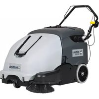
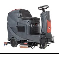
SW 750 - Sweeper NILFISK - Free user manual and instructions
Find the device manual for free SW 750 NILFISK in PDF.

| Product type | Sweeper |
| Brand | NILFISK |
| Model | SW 750 |
| Cleaning width (without side brush) | 500 mm |
| Cleaning width (with side brush) | 720 mm |
| Dimensions (L x W x H) | 998 x 797 x 501 mm (handlebar tilted forward) |
| Total weight (with standard batteries) | 68 kg |
| Waste container capacity | 60 L |
| Electrical system voltage | 12 V |
| Standard battery | 12 V, 45 Ah, GEL (maintenance-free) |
| Optional battery | 12 V, 80 Ah, GEL |
| Battery charger | 6 A |
| Main motor | 200 W, 1,500 rpm |
| Side brush motor | 40 W |
| Suction system motor | 50 W |
| Central brush rotation speed | 335 rpm |
| Side brush rotation speed | 100 rpm |
| Maximum drive speed | 3.7 km/h |
| Maximum slope capability | 2% |
| Dust filter | Polyester, 5-10 μm, surface area 1 m² |
| Sound pressure level (LpA) | 59.3 ±3 dB(A) |
| Sound power level (LwA) | 78 dB(A) |
| Hand-arm vibration level | < 2.5 m/s² |
| Working temperature | 0°C to +40°C |
| Intended use | Cleaning of smooth and solid floors in civil and industrial environments |
Frequently Asked Questions - SW 750 NILFISK
User questions about SW 750 NILFISK
0 question about this device. Answer the ones you know or ask your own.
Ask a new question about this device
Download the instructions for your Sweeper in PDF format for free! Find your manual SW 750 - NILFISK and take your electronic device back in hand. On this page are published all the documents necessary for the use of your device. SW 750 by NILFISK.
USER MANUAL SW 750 NILFISK
1.2 in - 2 in
3 cm - 5 cm
S311352
CONSERVATION DU MANUEL 2
DECLARATION DE CONFORMITE 2
DONNEES D'IDENTIFICATION 2
ACCESSIONS / OPTIONS 6
MACHINE AU TRAVAIL 9
VIDANGE DU CONTENEUR DECHETS 9
APRES L'UTILISATION DE LA MACHINE 9
INACTIVITE PROLONGEE DE LA MACHINE 9
PREMIERE PERIODE D'UTILISATION 9
ENTRETIEN 10
PLAN D'ENTRETIEN PROGRAMME 10
CONTROLE DU CABLE DU CHARGEUR DE BATTERIE 10
CONTROLE ET REGLAGE DE LA HAUTEUR DU BALAI LATERAL 11
DEPOSE / REPOSE DU BALAI LATERAL 11
CONTROLE ET REGLAGE DE LA HAUTEUR DU BALAI CENTRAL 12
DEPOSE / REPOSE DU BALAI CENTRAL 13
NETTOYAGE ET CONTROLE DE L'INTEGRITE DU FILTR A POUSSIÈRE, CONTROLE DES JOINTS
D'ETANCHEITE DU CONTENEUR DECHETS 14
CONTROLE DE LA HAUTEUR ET DU FONCTIONNEMENT DES VOLETS 15
CHARGEMENT DES BATTERIES 15
DEPISTAGE DES PANNES 16
MISE A LA FERRAILLE 16
INTRODUCTION

REMARQUE
CONSERVATION DU MANUEL
ACCESSORIES / OPTIONS
DEPOSE / REPOSE DU BALAI LATERAL

AVERTISSEMENT!

1.2 in - 2 in
3 cm - 5 cm
S311352
Figure 3
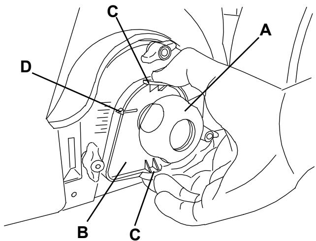
Figure 4
S311353
DEPOSE / REPOSE DU BALAI CENTRAL

AVERTISSEMENT!
MANUAL PURPOSE AND CONTENTS 2
TARGET 2
HOW TO KEEP THIS MANUAL 2
DECLARATION OF CONFORMITY 2
IDENTIFICATION DATA 2
OTHER REFERENCE MANUALS 2
SPARE PARTS AND MAINTENANCE 2
CHANGES AND IMPROVEMENTS 2
MACHINE STRUCTURE AND CONTROLS 5
ACCESSIONS/OPTIONS 6
TECHNICAL DATA. 6
WIRING DIAGRAM 7
USE 8
BATTERY CHECK ON A NEW MACHINE 8
BEFORE STARTING THE MACHINE 8
STARTING AND STOPPING THE MACHINE 8
MACHINE OPERATION 9
HOPPER EMPTYING 9
AFTER USING THE MACHINE 9
MACHINE LONG INACTIVITY 9
FIRST PERIOD OF USE 9
MAINTENANCE 10
SCHEDULED MAINTENANCE TABLE 10
BATTERY CHARGER CABLE CHECK 10
SIDE BROOM HEIGHT CHECK AND ADJUSTMENT 11
SIDE BROOM DISASSEMBLY/ASSEMBLY 11
MAIN BROOM HEIGHT CHECK AND ADJUSTMENT 12
MAIN BROOM DISASSEMBLY/ASSEMBLY 13
DUST FILTER CLEANING AND INTEGRITY CHECK, HOPPER GASKET CHECK 14
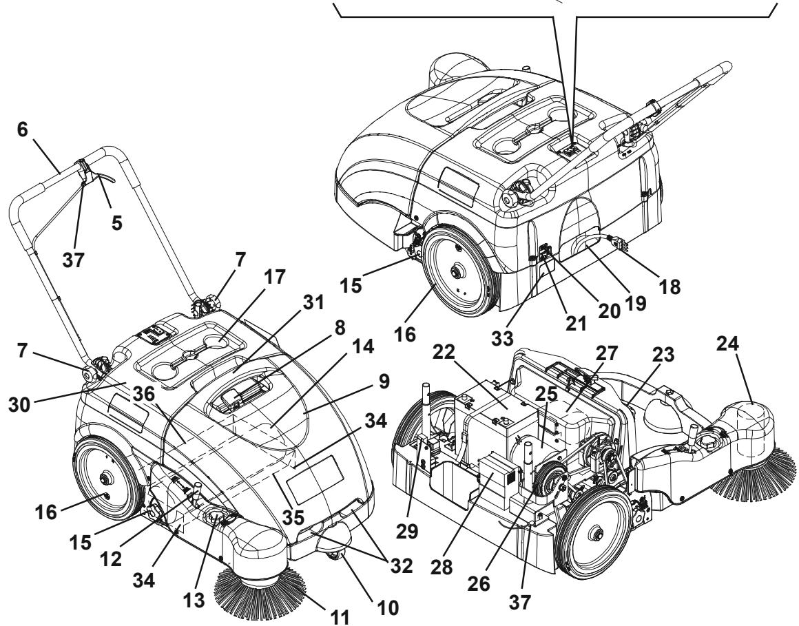
The numbers in brackets refer to the components shown in Machine Description chapter.
MANUAL PURPOSE AND CONTENTS
The purpose of this Manual is to provide the operator with all necessary information to use the machine properly in a safe and autonomous way. It contains information about technical data, safety, operation, storage, maintenance, spare parts and disposal. Before performing any procedure on the machine, the operators and qualified technicians must read this Manual carefully. Contact Nilfisk in case of doubts regarding the interpretation of the instructions and for any further information.
TARGET
This Manual is intended for operators and technicians qualified to perform the machine maintenance.
The operators must not perform procedures reserved for qualified technicians. Nilfisk will not be answerable for damages coming from the non-observation of this prohibition.
HOW TO KEEP THIS MANUAL
The User Manual must be kept near the machine, inside an adequate case, away from liquids and other substances that can cause damage to it.
DECLARATION OF CONFORMITY
The declaration of conformity, supplied with the machine, certifies the machine conformity with the law in force.

NOTE
Two copies of the original declaration of conformity are provided together with the machine documentation.
IDENTIFICATION DATA
The machine model and serial number are marked on the plate (33).
The machine model year is written in the declaration of conformity and it is also indicated by the first two figures of the machine serial number.
This information is useful when requiring machine spare parts. Use the following table to write down the machine identification data.
MACHINE model
MACHINE serial number
OTHER REFERENCE MANUALS
- Spare Parts List (supplied with the machine)
Service Manual (that can be consulted at Nilfisk Service Centers)
SPARE PARTS AND MAINTENANCE
All necessary operating, maintenance and repair procedures must be performed by qualified personnel or by Nilfisk Service Centers. Only original spare parts and accessories must be used.
Contact Nilfisk for service or to order spare parts and accessories, specifying the machine model and serial number.
CHANGES AND IMPROVEMENTS
Nilfisk constantly improves its products and reserves the right to make changes and improvements at its discretion without being obliged to apply such benefits to the machines that were previously sold.
Any change and/or addition of accessories must be approved and performed by Nilfisk.
This sweeper has been designed and built to clean (by sweeping and vacuuming) smooth and solid floors, in civil and industrial environments and to collect dust and light debris under safe operation conditions by a qualified operator.
CONVENTIONS
Forward, backward, front, rear, left or right are intended with reference to the operator's position, that is to say with the hands on the handlebar (6).
UNPACKING/DELIVERY
Upon delivery check that the packing and the machine were not damaged during transportation. In case of visible damages, keep the packing and have it checked by the carrier that delivered it. Call the carrier immediately to fill in a damage claim.
Check that the machine is equipped with the following features:
Technical documents:
- Sweeper User Manual
- Sweeper Spare Parts List
No. 1 vacuum system motor fuse
SAFETY
The following symbols indicate potentially dangerous situations. Always read this information carefully and take all necessary precautions to safeguard people and property.
The operator's cooperation is essential in order to prevent injury. No accident prevention program is effective without the total cooperation of the person responsible for the machine operation. Most of the accidents that may occur in a factory, while working or moving around, are caused by failure to comply with the simplest rules for exercising prudence. A careful and prudent operator is the best guarantee against accidents and is essential for successful completion of any prevention program.
SYMBOLS

DANGER!
It indicates a dangerous situation with risk of death for the operator.

WARNING!
It indicates a potential risk of injury for people.

CAUTION!
It indicates a caution or a remark related to important or useful functions.
Pay careful attention to the paragraphs marked by this symbol.

NOTE
It indicates a remark related to important or useful functions.

CONSULTATION
It indicates the necessity to refer to the User Manual before performing any procedure.
GENERAL INSTRUCTIONS
Specific warnings and cautions to inform about potential damages to people and machine are shown below.

DANGER!
Before performing any maintenance, cleaning or replacement procedure turn the main switch to "0" and, if necessary, disconnect the battery.
- This machine must be used by properly trained operators only. Children or disabled people cannot use this machine.
- Keep the battery away from sparks, flames and incandescent material.
- Do not wear jewels when working near electrical components.
- Do not work under the lifted machine without supporting it with safety stands.
- Do not operate the machine near toxic, dangerous, flammable and/or explosive powders, liquids or vapours. This machine is not suitable for collecting dangerous powders.

WARNING!
Before using the battery charger, ensure that frequency and voltage values, shown on the machine serial number plate, match the electrical mains voltage.
- Do not pull or carry the machine by the battery charger cable and never use the battery charger cable as a handle. Do not close a door on the battery charger cable, or pull the battery charger cable around sharp edges or corners. Do not run the machine on the battery charger cable.
- Keep the battery charger cable away from heated surfaces.
- Do not charge the batteries if the battery charger cable or the plug are damaged. If the battery charger cable is damaged, contact Nilfisk Service Center.
- To reduce the risk of fire, electric shock, or injury, do not leave the machine unattended when it is plugged in. Before performing any maintenance procedure, disconnect the battery charger cable from the electrical mains.
If the machine is not working as it should, has been damaged, left outdoors or dropped into water, return it to the Service Center.
- Do not smoke while charging the batteries.
- Do not leave the machine unattended without being sure that it cannot move independently.
- Always protect the machine against the sun, rain and bad weather, both under operation and inactivity condition. Store the machine indoors, in a dry place. This machine must be used in dry conditions, it must not be used or kept outdoors in wet conditions.
Before using the machine, close all doors and/or covers.
- Do not use the machine in excessively dusty areas.
- Do not allow to be used as a toy. Close attention is necessary when used near children.
- Use only as shown in this Manual. Use only Nilfisk's recommended accessories.
Take all necessary precautions to prevent hair, jewels and loose clothes from being caught by the machine moving parts.
- Do not wash the machine with direct or pressurised water jets, or with corrosive substances. Do not use compressed air to clean this type of machine.
- While using this machine, take care not to cause damage to other people, and children especially.
- Do not put any can containing fluids on the machine.
- The machine storage temperature must be between 0^ and +40^ .
- The machine working temperature must be between 0^ and +40^ .
The humidity must be between 30% and 95% .
- Do not use the machine as a means of transport.
- Do not use the machine on slopes with a gradient exceeding the specifications.
- Do not allow the brooms to operate while the machine is stationary to avoid damaging the floor.
In case of fire, possibly use a powder fire extinguisher, not a water one.
- Do not bump into shelves or scaffoldings, especially where there is a risk of falling objects.
- Adjust the operation speed to suit the floor conditions.
- This machine cannot be used on roads or public streets.
- Do not remove or modify the plates affixed to the machine.
- Do not tamper with the machine safety guards and follow the routine maintenance procedures scrupulously.
- Use only brooms supplied with the machine and those specified in the User Manual. Using other brooms could reduce safety.
In case of machine malfunctions, ensure that these are not due to lack of maintenance. Otherwise, request assistance from the authorised personnel or from an authorised Service Center.
- Carefully read all the instructions before performing any maintenance/repair procedure.
- To ensure machine proper and safe operation, the scheduled maintenance shown in the relevant chapter of this Manual must be performed by the authorised personnel or by an authorised Service Center.
If parts must be replaced, require ORIGINAL spare parts from an Authorised Dealer or Retailer.
- The machine must be disposed of properly, because of the presence of toxic-harmful materials (batteries, plastics, etc.), which are subject to standards that require disposal in special centres (see the Scrapping chapter).
MACHINE DESCRIPTION
MACHINE STRUCTURE AND CONTROLS
-
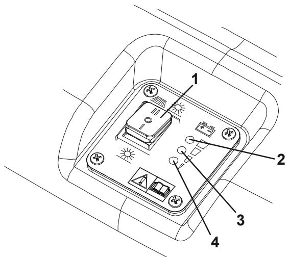
Main switch:
-
when turned to "I" the vacuum system and main broom are turned on;
-
when turned to "II" the vacuum system, main broom and side broom are turned on.
-
Charged battery warning light (green)
- Semi-discharged battery warning light (yellow)
- Discharged battery warning light (red)
- Drive control lever
- Handlebar
- Handlebar adjusting knobs
- Filter shaker knob
- Hopper
- Front steering wheel
- Side broom
- Side broom lifting/lowering lever
- Side broom height adjusting knob
- Main broom
- Main broom height adjusting knobs
- Rear driving wheels
- Can holder
- Battery charger cable
- Battery charger cable housing
- Side broom motor circuit breaker
- Main motor circuit breaker
- Battery
- Dust filter
- Side broom motor
- Main motor
- Drive system gear
- Vacuum fan
-
Battery charger
-
Vacuum system motor lamellar fuse (7.5 A)
- Hood
- Hopper upper handle
- Hopper lower handles
- Serial number plate/technical data/conformity certification
- Side skirts
- Front skirt
- Rear skirt
- Drive belt adjuster
ACCESSORIES/OPTIONS
In addition to the standard components, the machine can be equipped with the following accessories/options, according to the machine specific use:
- Brooms of different materials
- 80 Ah battery
- Non-marking skirts

NOTE
For further information concerning the optional accessories, contact an authorised Retailer.
TECHNICAL DATA
| General | Values |
| Cleaning width (without side broom) | 500 mm |
| Cleaning width (with side broom) | 720 mm |
| Machine size with folded handlebar and without side broom (length x width x height) | 998 x 797 x 501 mm |
| Minimum distance from the floor (skirts not included) | 25 mm |
| Main broom size (diameter x length) | 200 x 500 mm |
| Side broom diameter | 315 mm |
| Main broom speed | 335 rpm |
| Side broom speed | 100 rpm |
| Gradeability | 2% |
| Hopper capacity | 60 litres |
| Total machine weight (with standard battery) | 68 kg |
| Front steering wheel size (diameter x length) | 75 x 32 mm |
| Rear wheel size (diameter x length) | 300 x 45 mm |
| Maximum drive speed | 3.7 km/h |
| Sound pressure level at workstation (ISO 11201, ISO 4871) (LpA) | 59.3 ±3 dB(A) |
| Machine output acoustic power (ISO 3744, ISO 4871) (LwA) | 78 dB(A) |
| Vibration level at the operator's arms (ISO 5349-1) | < 2.5 m/s2 |
| Electrical components | Values |
| Electrical system voltage | 12 V |
| Standard battery | GEL, 12 V, 45 Ah |
| Optional battery | GEL, 12 V, 80 Ah |
| Battery charger | 6 A |
| Main motor | 200 W, 1,500 rpm |
| Side broom motor | 40 W |
| Vacuum system motor | 50 W |
| Dust vacuuming and filtering | Values |
| Dust filter | 5–10 μm (polyester) |
| Dust filter surface | 1 m² |
| Main broom compartment vacuum | 12 mm H₂O |
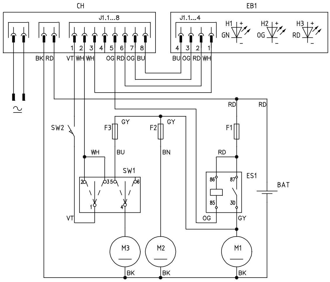
WIRING DIAGRAM
Key
| BAT | Batteries |
| CH1 | Battery charger |
| EB1 | Electronic board LED |
| ES1 | Relay |
| F1 | Main fuse |
| F2 | Vacuum fan fuse |
| F3 | Side broom fuse |
| M1 | Main motor |
| M2 | Vacuum system motor |
| M3 | Side broom motor |
| SW1 | Main switch |
| SW2 | Hopper microswitch |
Colour code
| BK | Black |
| BU | Blue |
| BN | Brown |
| GN | Green |
| GY | Grey |
| OG | Orange |
| PK | Pink |
| RD | Red |
| VT | Violet |
| WH | White |
| YE | Yellow |
S311349
USE
S311348AB

DANGER
WARNING
- CAUTION
- NOTE
While reading this Manual, the operator must pay careful attention to the symbols shown on the plates.
Do not cover these plates for any reason and immediately replace them if they are damaged.
BATTERY CHECK ON A NEW MACHINE
The machine is supplied with a standard 12 V, 45 Ah GEL battery (which does not require maintenance).
BEFORE STARTING THE MACHINE
- Make sure that there are no open doors/woods and that the machine is in normal operating conditions.
- If the machine has not been used after being transported, check that all the blocks used for the transportation have been removed.
- Check that side and main broom are installed, otherwise install them (see the procedure in Maintenance chapter).
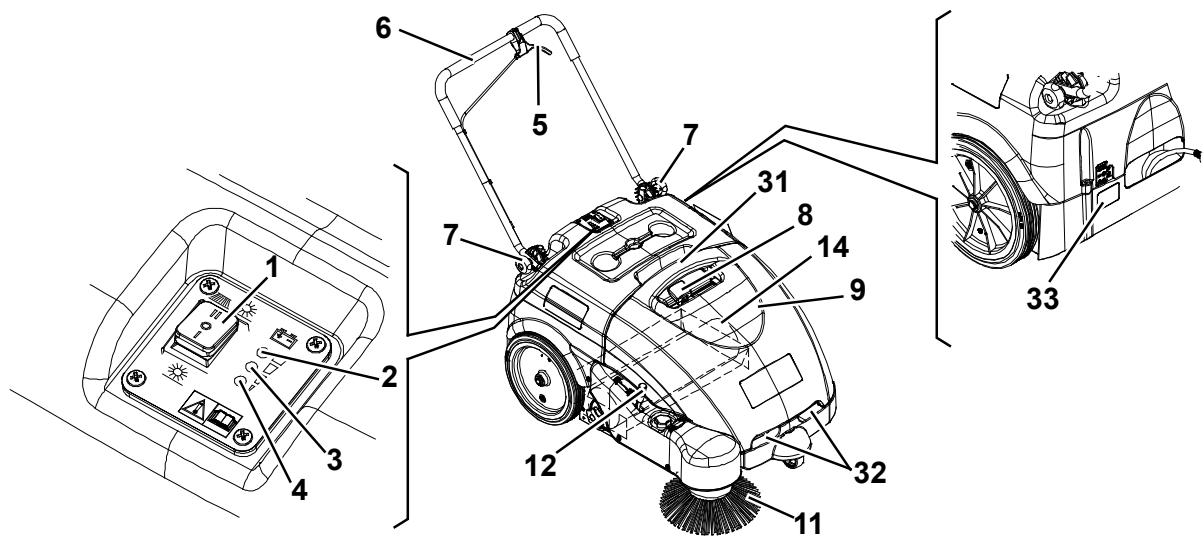
STARTING AND STOPPING THE MACHINE
Starting the machine
- Adjust the handlebar (6) to reach a comfortable position, by loosening the knobs (7).
When the adjustment is completed, tighten the knobs.
- To use the main broom only (14), turn the main switch (1) to "I".
To use also the side broom (11), turn the main switch (1) to "II", then lower the side broom by disengaging the lever (12). Check that the green warning light (2) (charged battery) turns on.
If the yellow or red warning light (3 or 4) turns on, turn the main switch (1) back to "0" and charge the batteries (see the procedure in Maintenance chapter).

NOTE
The side broom (11) can be lifted and lowered even if it is turned on.
- Start sweeping by grasping the handlebar (6) and pulling the drive control lever (5) gradually.
Stopping the machine
- Release the drive control lever (5) to stop the drive system.
- Turn off the vacuum system and the brooms, by turning the main switch (1) to "0".
- Lift the side broom (11) by pulling the lever (12) backwards and by engaging it to the fastener.
MACHINE OPERATION
- Avoid stopping for a long time with the machine in the same position and the brooms turning: this could create unwanted marks on the floor.
- For machine proper operation, the dust filter must be as clean as possible. Therefore the filter shaker must be used at regular intervals (every 10 minutes, but this interval may vary according to the floor conditions), according to the following procedure.
- Stop the machine and turn the main switch (1) to "0".
To shake the filter, move the filter shaker knob (8) to the right and then to the left several times. - Turn the main switch (1) to "I" or to "II" and start sweeping again.

NOTE
When the dust filter is clogged, the machine cannot collect dust and debris anymore.

CAUTION!
If the machine is to be used on wet floors, use it only for short intervals.
- The hopper (9) should be emptied after each working cycle and whenever it is full.

NOTE
When the hopper is full, the machine cannot collect dust and debris anymore.
HOPPER EMPTYING
Stop the machine and turn the main switch (1) to "0".
Remove the hopper (9) by using the handles (31) and (32), then empty it at the waste collection centre.
Then install the hopper.
The machine is ready to start sweeping again.

NOTE
When the hopper is removed, all machine functions are disabled.
AFTER USING THE MACHINE
After working, before leaving the machine:
- Turn the main switch (1) to "0".
- Turn on the filter shaker with the knob (8).
- Empty the hopper (9) (see the procedure in the previous paragraph).
- Lift the side broom (11) by pulling the lever (12) backwards and by engaging it to the fastener.
- Make sure that the machine cannot move independently.
- Charge the batteries (see the procedure in Maintenance chapter).
MACHINE LONG INACTIVITY
If the machine is not going to be used for more than 30 days, proceed as follows:
- Perform the daily maintenance procedures (see the Maintenance chapter).
- Check that the machine storage area is dry and clean.
- Slightly lift the machine so that the skirts, the main broom and the wheels do not touch the ground.
FIRST PERIOD OF USE
After the first 8 hours, check the machine fastening and connecting parts for proper tightening and check the visible parts for integrity and leakage.
MAINTENANCE
The lifespan of the machine and its maximum operating safety are ensured by proper and regular maintenance.
The following table provides the scheduled maintenance. The intervals shown may vary according to particular working conditions, which are to be defined by the person in charge of the maintenance.

WARNING!
To perform maintenance procedures, the machine must be off and, if necessary, the batteries must be disconnected.
Moreover, carefully read the instructions in Safety paragraph.
All scheduled or extraordinary maintenance procedures must be performed by qualified personnel, or by an authorised Service Center.
This Manual describes only the easiest and most common maintenance procedures.

NOTE
For other maintenance procedures shown in the Scheduled Maintenance Table, refer to the Service Manual that can be consulted at any Service Center.
SCHEDULED MAINTENANCE TABLE
| Procedure | Every 10 hours | Every 50 hours | Every 200 hours | Every 400 hours |
| Battery charger cable check | ||||
| Side and main broom height check and adjustment | ||||
| Skirt height and operation check | ||||
| Dust filter cleaning and integrity check | ||||
| Hopper gasket check | ||||
| Filter shaker operation check | (*) | |||
| Driving belt and clutch visual inspection | (*) | |||
| Driving belt tensioner adjustment | (*) | |||
| Nut and screw tightening check | (*) (1) | |||
| Motor carbon brush check or replacement | (*) |
(*) For the relevant procedure, see the Service Manual.
(1) And after the first 8 hours.
BATTERY CHARGER CABLE CHECK
Carefully check the battery charger cable (18) and the relevant plug for wear, cuts, cracks or other damages.
If the battery charger cable or the relevant plug is damaged, contact the Nilfisk Service Center.
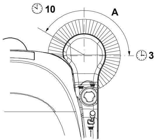
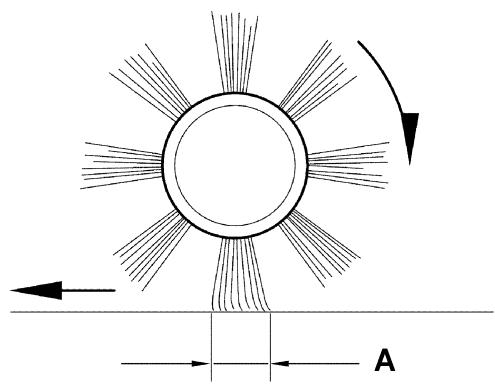
SIDE BROOM HEIGHT CHECK AND ADJUSTMENT
-
Check the side broom distance from the floor as shown below:
-
Drive the machine on a level ground and lower the side broom.
- Keep the machine stationary and turn on the side broom for a few seconds.
- Turn off the side broom by pressing the switch (1), then lift it and move the machine.
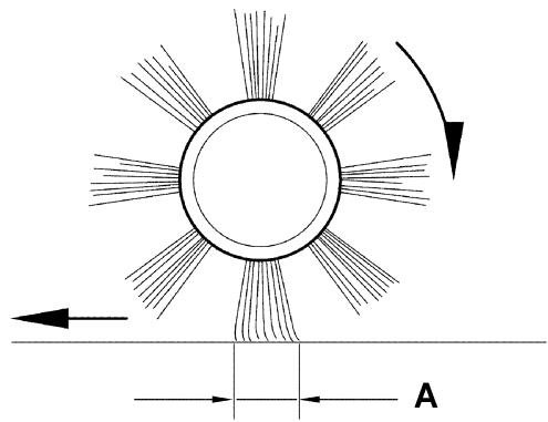
- Check that the side broom print is as shown in the figure (A, Fig. 1): the side broom must touch the ground along a circle arc ranging from "10 o'clock" position to "3 o'clock" position.
-
If the print is not within specifications, adjust the broom height as shown in step 2.
-
Turn the knob (13) clockwise and counter-clockwise to adjust the broom height.
- Perform step 1 again to check the proper adjustment of the side broom height.
- When the broom is too worn to be adjusted, replace it as shown in the next paragraph.
SIDE BROOM DISASSEMBLY/ASSEMBLY

CAUTION!
It is advisable to wear protective gloves when replacing the side broom because there can be sharp debris between the bristles.
- Drive the machine on a level floor.
- Turn the main switch (1) to "0".
- Lift the side broom.
- Loosen the knob (A, Fig. 2) inside the side broom, then remove the broom (B) by disengaging it from the pins (C).
- Install the new broom by engaging it on the pins (C), then tighten the knob (A).
- Adjust the new broom height as shown in the previous paragraph.
S311350
Figure 1
S311351
Figure 2
MAIN BROOM HEIGHT CHECK AND ADJUSTMENT
-
Check the main broom distance from the floor as shown below:
-
Drive the machine on a level floor.
- Keep the machine stationary and turn on the main broom for a few seconds.
- Turn off the main broom by pressing the switch (1), then move the machine.
- Check that the main broom print (A, Fig. 3), along its length, is 3 - 5cm wide.
-
If the print is not within specifications, adjust the broom height as shown in step 2.
-
Turn the main switch (1) to "0".
- Loosen the knob (A, Fig. 4) on both sides of the machine.
- Grasp the support (B) on the points (C) and move it upwards, then lift it or lower it to change the main broom height. For height variation, refer to the indicator (D). Then tighten the knob (A) on both sides of the machine.
- Perform step 1 again to check the proper adjustment of the main broom height.
- When the broom is too worn to be adjusted, replace it as shown in the next paragraph.

CAUTION!
If the main broom print is excessive (larger than 5 cm), the machine regular operation is affected and the moving or electrical parts can overheat, thus reducing machine life.
Pay careful attention when performing the above-mentioned checks, and always use the machine according to the indicated conditions.

1.2 in - 2 in
3 cm - 5 cm
S311352
Figure 3
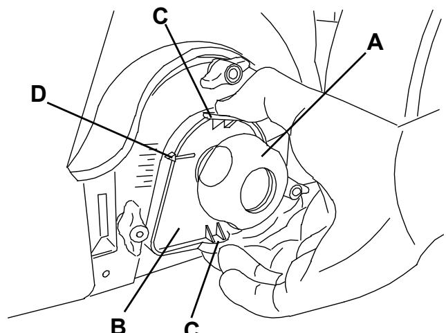
Figure 4
S311353
MAIN BROOM DISASSEMBLY/ASSEMBLY

CAUTION!
It is advisable to wear protective gloves when replacing the main broom because there can be sharp debris between the bristles.
- Drive the machine on a level floor.
- Turn the main switch (1) to "0".
- Remove the hopper (9).
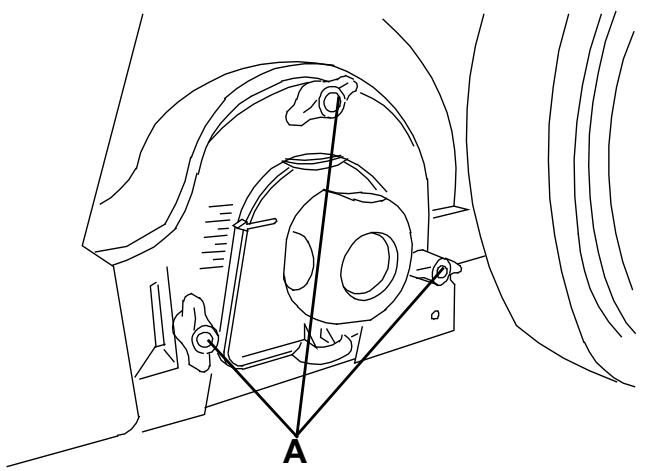
- Loosen the handwheels (A, Fig. 5) completely on the left side of the machine.
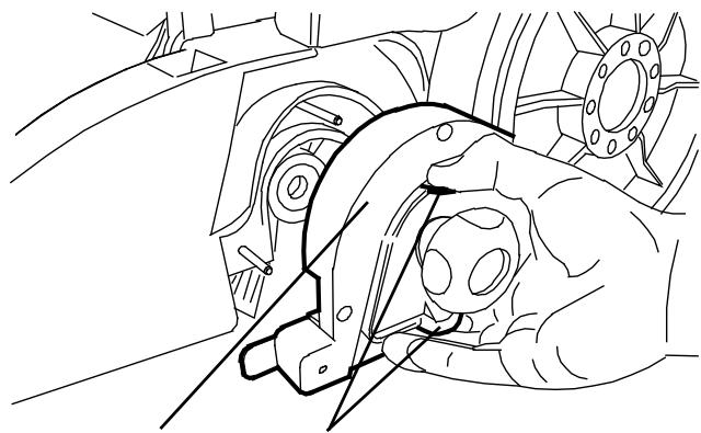
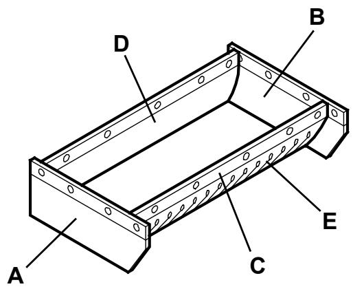
- Remove the lid (A, Fig. 6) by grasping it on the points (B).
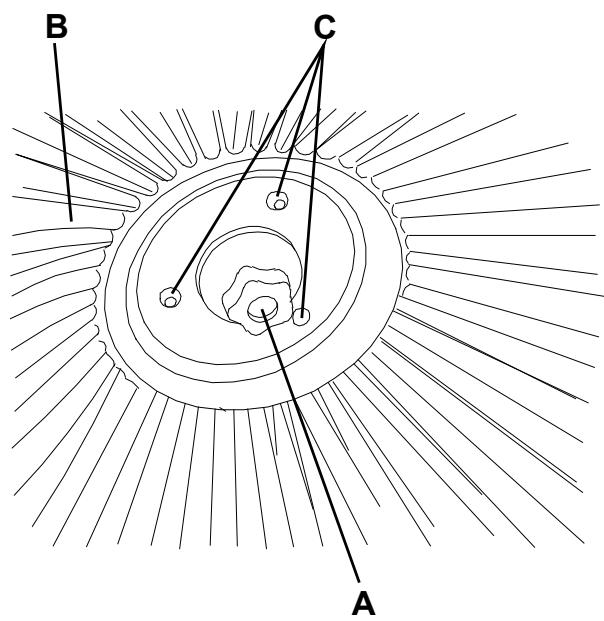
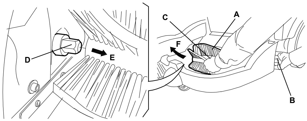
- Grasp the main broom (A, Fig. 7) on the points (B) and (C), then disconnect it from the drive hub (D) by pulling it in the direction shown by the arrow (E); then remove it in the direction shown by the arrow (F).
- The new main broom must be installed with the bristles rows bent as shown in the figure.
- Install the new broom by performing steps 3 to 6 in the reverse order.
- Adjust the new broom height as shown in the previous paragraph.
S311354
Figure 5
A
B
S311355
Figure 6
Figure 7
S311356
DUST FILTER CLEANING AND INTEGRITY CHECK, HOPPER GASKET CHECK
- Drive the machine on a level floor.
- Turn the main switch (1) to "0".
- Remove the hopper (9).
- Loosen the knobs (A, Fig. 8).
- Grasp the dust filter (B) as shown in the figure.
- Remove the dust filter by turning it in the direction shown by the arrow (A, Fig. 9) to disengage it from the pins (B), then lower the filter to disengage it from the filter shaker combs (C).
- Remove the filter (A, Fig. 10) from the frame (B) by disengaging the 2 rubber bands (C).
- In an appropriate outdoor area, clean the filter by shaking it on a level and clean surface, tapping the side (D) opposite to the gasket (E).
Complete the cleaning procedure by using compressed air (F) at maximum 6 Bar, blowing only from the side of the gasket (E), at a minimum distance of 30~cm .
Check the filter body for tears. If necessary, replace it. For a better cleaning, it is allowed to wash the filter with water and non-lathering detergents. This provides better quality cleaning but reduces the life of the filter, which will have to be replaced more frequently. The use of inadequate detergents can damage the filter.
- Clean the bearing surface of the filter rubber gasket (E) and check it for integrity and sealing capabilities. If necessary, replace the filter.
- Clean the bearing surface of the hopper gasket (D, Fig. 9) and check it for integrity and sealing capabilities. If necessary, replace it.
- Assemble the components in the reverse order of disassembly.

NOTE
Assemble the filter with the gasket (E, Fig. 10) positioned as shown in the figure.
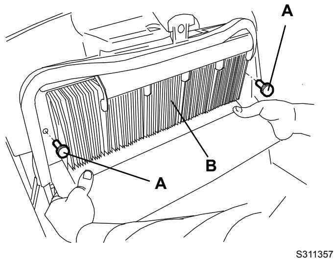
Figure 8
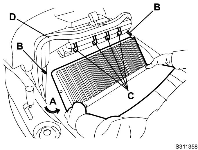
Figure 9
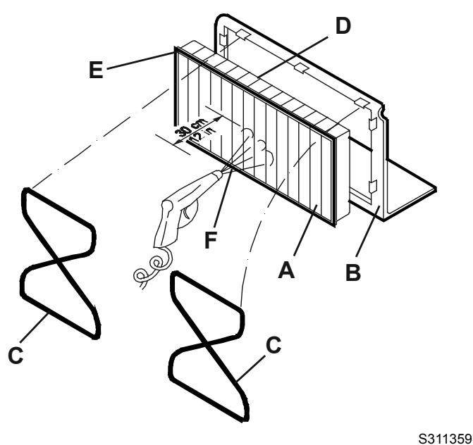
Figure 10
- Drive the machine on a level floor that is suitable for checking the skirt height.
- Turn the main switch (1) to "0".
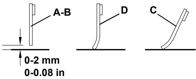
- Check that the distance from the ground of the side skirts (A and B, Fig. 11) is 0 - 2 ~mm .
Check the skirts for integrity, cuts or tears, which can reduce the machine vacuum capabilities. If necessary replace the side skirts (see the procedure in the Service Manual).
- Check that the front and rear skirts (C and D, Fig. 11) slightly rub on the ground. Check the skirts for integrity, cuts or tears, which can reduce the machine vacuum capabilities. Note that the front skirt has typical vertical cuts (E). If necessary replace the front and rear skirts (see the procedure in the Service Manual).
BATTERY CHARGING
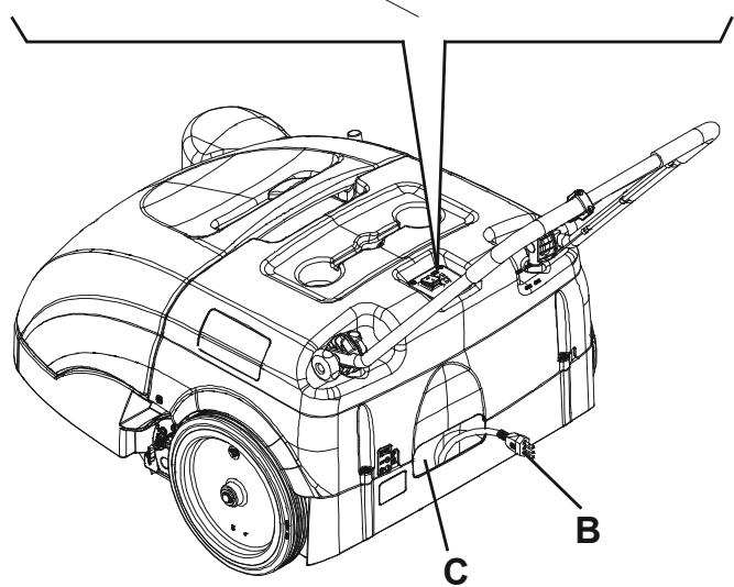
- Drive the machine to the appointed recharging area and ensure that it cannot move independently.
- Turn the main switch (A, Fig. 12) to "0".
- Remove the battery charger cable (B) from the housing (C) and connect it to the electrical mains.

CAUTION!
Before connecting the battery charger (B), ensure that frequency and voltage values, shown on the machine serial number plate (33), match the electrical mains voltage.
In case of doubt, do not connect the plug to the electrical mains, but contact the qualified personnel.
- While charging the batteries, the red warning light (D) and the yellow warning light (E) turn on in sequence.
When the green warning light (F) turns on, the batteries are charged. - Disconnect the battery charger cable (B) from the electrical mains and place it in the housing (C).

NOTE
When the battery charger is connected to the electrical mains, all machine functions are automatically disabled.
S311360
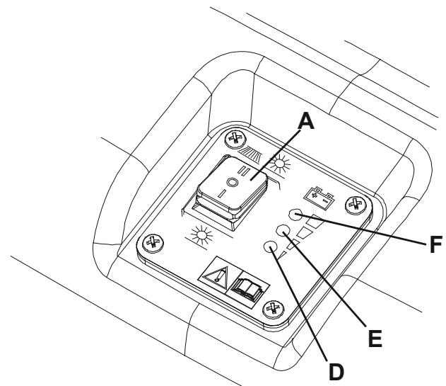
Figure 11
Figure 12
S311361
TROUBLESHOOTING
| Trouble | Possible cause | Remedy |
| The machine does not start when turning the main switch to "I" or to "II". | There is an open in the fuse (21). | Reset the fuse by pressing the relevant push-button. |
| The battery charger cable is connected to the electrical mains. | Disconnect it and place it in the housing. | |
| The batteries are discharged. | Charge the batteries. | |
| The side broom does not operate. | There is an open in the fuse (20). | Reset the fuse by pressing the relevant push-button. |
| The machine operates only when stationary, otherwise the red warning light turns on. | The batteries are discharged. | Charge the batteries. If the trouble persists, have the batteries replaced at Nilfisk Service Center. |
| The battery autonomy is low. | The batteries are dead. | Have the batteries replaced at Nilfisk Service Center. |
| The batteries do not charge: the red warning light (4) does not turn on when the plug is inserted in the electrical mains socket. | There is no power supply at the electrical mains socket. | Check the electrical mains socket by trying to connect another domestic appliance. |
For further information, refer to the Service Manual, available at any Nilfisk Service Center.
SCRAPPING
Have the machine scrapped by a qualified scrapper.
Before scrapping the machine, remove and separate the following materials, which must be disposed of properly according to the Law in force:
Battery
Brooms
- Plastic hoses and components
- Electrical and electronic components (*)
(*) Refer to the nearest Nilfisk Center especially when scrapping electrical and electronic components.
INHOUDSOPGAVE
INLEIDING 2
DOEL EN INHOUD VAN DEZE HANDLEIDING 2
BETREFFENDE PERSONEN 2
OPBERGEN VAN DE HANDLEIDING 2
CONFORMITEITSVERKLARING 2
IDENTIFICATIEGEGEVENS 2
ANDERE GEBRUKERSHANDLEIDENGIN 2
VERVANGINGSONDERDELEN EN ONDERHOUD 2
MODIFICATIES EN VERBETERINGEN 2
BEDRIJFSCAPACITEIT 2
ALGEMENE OPMERKINGEN 2
VERPAKKING VERWIJDEREN/AFLEVERING 3
VEILIGHEID 3
GEBRUIKTE SYMBOLEN 3
ALGEMENE INSTRUCTIONS 3
BESCHRIJVING VAN DE MACHINE 5
OPBOUW EN BEDIENINGSELEMENTEN VAN DE MACHINE. 5
ACCESSIONS / OPTIES 6
1.2 in - 2 in
3 cm - 5 cm
S311352