Energysilence Aero 570 - Ceiling fan CECOTEC - Free user manual and instructions
Find the device manual for free Energysilence Aero 570 CECOTEC in PDF.


| Product type | Ceiling fan |
| Brand | Cecotec |
| Model | Energysilence Aero 570 |
| Blade diameter | 132 cm |
| Number of blades | 5 |
| Blade material | ABS |
| Color | White |
| Motor type | DC motor |
| Power | 50 W |
| Voltage | 220-240 V / 50 Hz |
| Number of speeds | 6 |
| Remote control | Yes, included |
| Winter/summer function | Yes, reverse rotation |
| Timer | Yes (1 to 8 hours) |
| Recommended installation height | 2.5 m |
| Net weight | 5.5 kg |
| Dimensions | 132 cm diameter, 30 cm height |
| Noise level | 25 dB |
| Maximum airflow | 570 m³/h |
| Blade pitch angle | 15° |
| Warranty | 2 years |
Frequently Asked Questions - Energysilence Aero 570 CECOTEC
User questions about Energysilence Aero 570 CECOTEC
0 question about this device. Answer the ones you know or ask your own.
Ask a new question about this device
Download the instructions for your Ceiling fan in PDF format for free! Find your manual Energysilence Aero 570 - CECOTEC and take your electronic device back in hand. On this page are published all the documents necessary for the use of your device. Energysilence Aero 570 by CECOTEC.
USER MANUAL Energysilence Aero 570 CECOTEC
- Parts and components 32
- Before use 32
- Assembly 33
- Operation 35
- Cleaning and maintenance 36
- Troubleshooting 37
- Technical specifications 38
- Disposal of old electrical and electronic appliances 38
- Technical support and warranty 39
- Copyright 39
SOMMAIRE
Read these instructions thoroughly before using the product. Keep this instruction manual for future reference or new users.
- Make sure that the mains voltage matches the voltage stated on the rating label of the appliance and that the wall outlet is grounded.
- Do not use the product if its structure or any of its parts is damaged or not working properly, has been dropped, or damaged.
- This appliance can be used by children aged 8 years and above and persons with reduced physical, sensory, or mental capabilities or lack of experience and knowledge if they have been given supervision or instruction concerning the use of the appliance in a safe way and understand the hazards involved. Children must not play with the appliance. Cleaning and user maintenance should not be carried out by unsupervised children.
- The minimum distance between the fan blades and the floor must be 2.3 m.
- Make sure the appliance is unplugged from the power supply before cleaning or user maintenance.
- This appliance is designed for domestic use only and is not intended for bars, restaurants, farmhouses, hotels, motels, and offices.
- Do not use the appliance in spaces with explosive or toxic vapours.
-
The appliance shall be installed in accordance with national wiring regulations.
-
Never insert objects or body parts between rotating fan blades. To control the fan blades' speed, only use the means for speed control provided by Cecotec.
- To reduce the risk of injury, attach the fan directly to the support structure of the building as indicated in this manual and use only parts and components provided or recommended by Cecotec.
- Turn off the mains power by turning off the circuit breakers before installing your fan to avoid risk of electric shock.
- Do not bend the blade-attachment system during the installation or cleaning process.
- If you are mounting the fan to a joist, make sure it is strong enough as to support the moving weight of the fan (at least 50 kg). If you hang the fan on a hook, it must withstand at least 100 kg.
- After installing the fan, make sure all the connections are secured.
- Turn the fan off and wait for it to stop before reversing the fan direction.
- Make sure the installation location you choose allows the fan blades to rotate without any obstructions.
- Cleaning and maintenance must be carried out according to this instruction manual to make sure the device operates properly. Turn off the device and unplug it from the main power supply before cleaning it.
- Make sure the fan is not placed close to curtains or other objects it may become entangled with.
- To ensure your children's safety, please keep all packaging materials (plastic bags, boxes, polystyrene, etc.) away from their reach.
INSTRUCTIONS DE SÉCURITÉ
Tools and materials required (included)
- Mounting bracket
- Downrod and hanging ball
- Canopy
- Fan motor housing
- LED light
- Glass shade
- Blades
- Screw kit, tools for mounting bracket (cable nuts, rubber washers), and tools for fastening.
- Remote control
Tools and materials required (not included)
- Screwdriver
- Flat-blade screwdriver
- Adjustable pliers or wrench
- Step ladder
- Wire cutter
- Electrical tape
NOTE:
The graphics in this manual are schematic representations and may not exactly match the product.
2. BEFORE USE
- This appliance is packaged in a way as to protect it during transport. Take the device out of its box and remove all packaging materials. You can keep the original box and other packaging elements in a safe place. This will help you prevent product damage when transporting it in the future. In case the original packaging is disposed of, make sure all packaging materials are recycled accordingly.
- Make sure all parts and components are included and in good conditions. If there is any piece missing or not in good condition, immediately contact the Technical Support Service of Cecotec.
- Carefully open the ceiling fan's box, take all the components out, and place them on a cloth or soft surface to avoid damage. Do not lay the motor's box on its sides to avoid damage to the housing.
Box contents
- EnergySilence Aero 570 ceiling fan
- Assembly kit
- Remote control
- Instruction manual
3. ASSEMBLY
Warning
All electrical tasks should only be carried out after shutting off the electricity by removing fuses or turning off the circuit breaker to avoid risk of electric shocks.
Assembly steps
- Installation of the mounting bracket
- Installation of the downrod and hanger ball
- Hanging fan to bracket
- Remote control and wiring instruction
- Blade assembly
- Installing LED light and glass shade
Installation of the mounting bracket
Fig. 2.
- The hanger bracket must be screwed on to a firm flat surface. The structure to which it is installed must be able to withstand ten times the static weight of the fan. In case of installing the ceiling fan to a wooden joist, 2 self-tapping screws provided should be enough to support the ceiling fan. The washers provided must be placed in the following order: screw head > round washer > spring washer >mounting bracket > ceiling.
- Screw the mounting bracket to the ceiling and make sure all connections are secure to prevent the fan from falling. Loosen the two canopy screws from the mounting bracket.
Note: Self-tapping screws are only suitable for wooden ceilings. In case of installing the ceiling fan to concrete ceilings or joists, use a drill for making the holes and stoppers or expansion screws (not included).
Installation of the downrod and hanger ball
Fig. 3.
- Unscrew the screw on the downrod's hanger ball, then loosen the hanger ball. Remove the stop pin from inside the downrod and remove the hanger ball from the rod. Remove the clevis pin and hairpin clip from the downrod.. If you prefer using the longer downrod,, install the hanger ball on it and make sure to move the earth wire from one to the other. Pass the electrical supply leads from the top of the motor all the way through the downrod until they come out the other end.
Fig. 4.
- Insert the downrod into the motor housing's hole and turn it to align the holes on both sides with the holes on the down rod. Pass the clevis pin through the holes so that it passes through the downrod too. Be careful not to damage any of the wires. Pass the hairpin clip through the clevis pin so that it is securely fixed. Tighten all the screws set up to the moment. This will ensure minimum rod and fan tumbling.
Fig. 5.
- If screws are not properly tightened, the motor might oscillate. This could be dangerous. Once the steps above are all finished, install the hanger ball onto the downrod,, insert the stop pin in the downrod and lift the hanger ball. Then, tighten all the screws firmly so that all the elements are completely and securely fixed
Hanging the fan to the mounting bracket and attaching the blades
Fig. 6.
Lift the fan up to the mounting bracket, insert the hanger ball in the mounting bracket through the opening, and carefully let it rest. Rotate the ball and make sure that the tab located in the mounting bracket is aligned with the hanging ball's slot. When aligned, the fan will automatically sit on its correct position. This will prevent rotation of the rod and fan when the unit is operating.
Remote control and wiring instructions
Fig. 7.
-
Place the receiver through the hanging bracket and connect the wires following the colour codes.
-
Connect the push connectors from the fan to the remote control as stated below:
-
Black > black
- White > white
- Blue > blue
Fig. 8.
-
N (white)
-
L (black)
-
N (white)
- L (black)
-
Light (blue)
-
Blue (neutral)
- Brown (fan connection)
- Black (light connection)
Motor
Blade assembly
Fig. 9.
- Remove the three screws and the lamp holder from the fixing panel.
Fig. 10.
- Insert the blades through the motor housing's side slots and align them with the 3 holes. Secure the blades with 3 blade screws and ensure that the 3 blade screws are tightened properly. Do not over tighten the screws, as this can damage the blades. Repeat this process for all blades.
Note
If installing more than 1 fan, be careful not to mix blades and screws. Each model is designed with specific materials and parts.
Installing LED light and glass shade
Fig. 11.
- Align the lamp holder's screw holes with those on the motor and attach both parts by means of the screws provided.
Fig. 12.
- Connect the LED light's wires to the fan motor's wires.
Fig. 13.
- Carefully install the glass shade into the main body and turn it clockwise to lock it.
Warning
Do not over tighten when installing the glass shade.
4. OPERATION
- The direction switch on the fan's body controls air flow.
- Winter function: press the switch UP for the blades to move warm air near the ceiling around.
- Summer function: press the switch DOWN for blades to create breeze and improve air circulation.
- Warning: before using the direction switch, turn the fan off and make sure it has completely stopped moving to avoid personal and product damage. Turn the blade-rotation direction by turning the switch up or down while the fan is off.
Remote control
Use the remote control to turn the fan and the light on and off, and to change speed.
Fig. 14.
- Power light indicator
- Speed control
- Off button
- Timer
-
Light
-
The indicator will light up while the product is operating.
- Use the 3 speed buttons to select the air power level: low, medium, or high.
- Press the off button to turn the device off.
- Use the 4 timer buttons to select the fan's operation time: 1, 2, 4, or 8 hrs. The fan will turn off once the selected time has elapsed.
- Press the light button to turn the fan's lamp on and off.
- Press repeatedly to select one of the 3 available colours, the light will turn off and will turn back on.
Replacing cells
- To replace the remote control cells, press the battery cover and slide it towards the arrow direction.
- This remote control requires 1 x A23 12 V cell.
- Reassemble the cell compartment cover.
Warnings
- Always ensure the cell compartment cover is closed properly.
- Never leave the remote control directly exposed to sun light.
- Do not try recharging the discharged cells by heating them or with a cell charger.
- Rechargeable batteries are always specified as so.
- Do not throw cells into fire, as it could cause an explosion.
5. CLEANING AND MAINTENANCE
- Always turn disconnect the fan from the power supply and allow it to stop before cleaning it.
- Clean the outside surface with a soft damp cloth.
Warnings
- Make sure the power is turned off at the main fuse or circuit panel before you attempt any repairs.
- Do not immerse the fan in water.
-
Do not use any cleaning chemicals such as detergents and abrasives.
-
Clean your fan periodically. Use only a cloth or brush. Metal finishes are finished with a lacquer to prevent tarnishing.
- Do not allow the interior (special for the PCB) to get wet as this could create a hazard.
- When the unit is not in use, make sure that it is unplugged from the wall socket. To store the fan, you may pack it in the original carton and store it in a cool and dry place until later use.
- In case of fault or doubt, do not try to repair the fan by yourself to avoid risk of fire or electric shock.
6. TROUBLESHOOTING
The fan does not start up
- Check all the fuses or circuit breakers.
- Turn off the electrical power and check all wire connections.
The fan makes noises
- Always allow a few days "break in" time for any new fan at medium or high speed. Try to diagnose the exact location of the noise by listening carefully from several sides (blades, motor, light kit, etc.). The fan noise can come from a light kit.
- Make sure all screws in the fan assembly and light kit are tight and properly threaded. If not, back out and re-tighten. Tighten these screws at least once a year because they may loosen slowly over time and cause a clicking noise.
- Make sure the light kit is securely fastened to the fan, and all glass screws are finger-tightened only. Do not tighten with pliers or a screw driver.
- Make sure the mounting bracket is installed snugly to the junction box.
- Make sure wire nuts in the switch housing or the canopy are not rattling against each other or against the housing's wall. Wrap with electrical tape if necessary.
- Make sure the canopy is not touching the ceiling.
- Assure that the screws fastening the blade holders to the motor are tight and the lock washers provided for that purpose have been used.
The fan does not produce much air
- The fan may be running in reverse, so air is directed upward.
- The room may contain items that obstruct the airflow.
- The fan may be too small for the size of the room.
Blade wobbling
Note
A small amount of wobble is considered acceptable and should not be considered a defect.
ENGLISH
- Make sure the mounting bracket is fixed tightly to the ceiling with no movement at all. Tighten screws if necessary.
- Make sure all screws holding the blades to the blade support and blade support to motor are tight.
- Make sure the light kit and the glass screws are tight.
7. TECHNICAL SPECIFICATIONS
Model: EnergySilence Aero 570
Product reference: 05948
Power: 60 W
LED: 16 W
Voltage and frequency: 220-240 V, 50-60 Hz
| Description | Symbol | Value | Unit |
| Fan maximum flow | F | 145.1 | m^3/min |
| Fan power consumption | P | 52.3 | W |
| Service value | SV | 2.8 | (m^3/min) / W |
| Power consumption on standby mode | P_SB | 0.2 | W |
| Fan sound power level | L_WA | 48 | dB (A) |
| Maximum air speed | C | 2.1 | m/seg |
| Service value measurement standard | IEC 60879 | ||
| Contact details to obtain more information | Cecotec Innovaciones S.L.C/ de la Pinadeta s/n, 46930Quart de Poblet, Valencia (Spain) | ||
This product features a light source with an energy efficiency grade F.
Technical specifications may change without prior notification to improve product quality.
Made in China | Designed in Spain
8. DISPOSAL OF OLD ELECTRICAL AND ELECTRONIC APPLIANCES

This symbol indicates that, according to the applicable regulations, the product and/or cells must be disposed of separately from household waste. When this product reaches the end of its shelf life, you should dispose of the batteries/accumulators and take them to a collection point designated by the local authorities.
ENGLISH
Consumers must contact their local authorities or retailer for information concerning the correct disposal of old appliances and/or their batteries.
Compliance with the above guidelines will help protecting the environment.
9. TECHNICAL SUPPORT AND WARRANTY
Cecotec shall be liable to the end user or consumer for any lack of conformity that exists at the time of delivery of the product under the terms, conditions, and deadlines established by the applicable regulations.
It is recommended that repairs be carried out by qualified personnel.
If at any moment you detect any problem with your product or have any doubt, do not hesitate to contact Cecotec's official Technical Support Service at +34 963 210 728.
10. COPYRIGHT
The intellectual property rights over the texts in this manual belong to CECOTEC INNOVACIONES, S.L. All rights reserved. The contents of this publication may not, in whole or in part, be reproduced, stored in a retrieval system, transmitted, or distributed by any means (electronic, mechanical, photocopying, recording or similar) without the prior authorization of CECOTEC INNOVACIONES, S.L.
1. PIÈCES ET COMPOSANTS
Img. 1.
6. PROBLEEMOPLOSSING
Fig./Img./Abb./Rys./Obr. 2
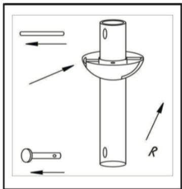
Fig./Img./Abb./Rys./Obr. 3
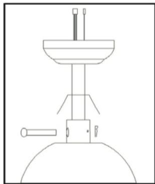
Fig./Img./Abb./Rys./Obr. 4

Fig./Img./Abb./Rys./Obr. 5
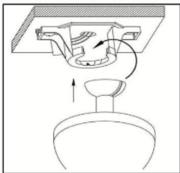
Fig./Img./Abb./Rys./Obr.6
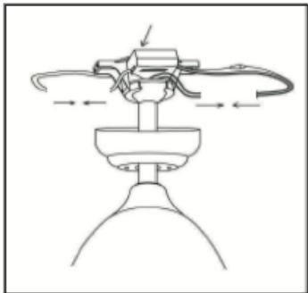
Fig./Img./Abb./Rys./Obr.7

Fig./Img./Abb./Rys./Obr.8

Fig./Img./Abb./Rys./Obr.9
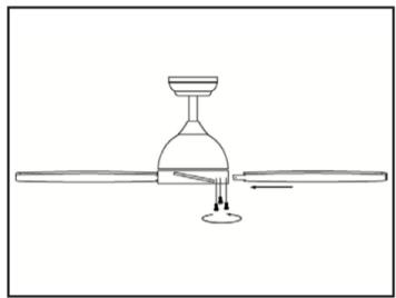
Fig./Img./Abb./Rys./Obr.10

Fig./Img./Abb./Rys./Obr.11
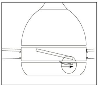
Fig./Img./Abb./Rys./Obr.12
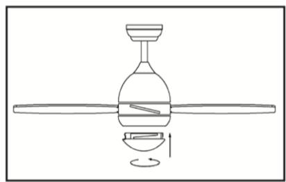
Fig./Img./Abb./Rys./Obr.13

Fig./Img./Abb./Rys./Obr.14
www.cecotec.es
- SOMMAIRE
- INSTRUCTIONS DE SÉCURITÉ
- Tools and materials required (included)
- Tools and materials required (not included)
- NOTE:
- BEFORE USE
- Box contents
- ASSEMBLY
- Warning
- Assembly steps
- Installation of the mounting bracket
- Installation of the downrod and hanger ball
- Hanging the fan to the mounting bracket and attaching the blades
- Remote control and wiring instructions
- Motor
- Blade assembly
- Note
- Installing LED light and glass shade
- OPERATION
- Remote control
- Fig. 14.
- Replacing cells
- Warnings
- CLEANING AND MAINTENANCE
- TROUBLESHOOTING
- The fan does not start up
- The fan makes noises
- The fan does not produce much air
- Blade wobbling
- ENGLISH
- TECHNICAL SPECIFICATIONS
- DISPOSAL OF OLD ELECTRICAL AND ELECTRONIC APPLIANCES
- TECHNICAL SUPPORT AND WARRANTY
- COPYRIGHT
- PIÈCES ET COMPOSANTS
- PROBLEEMOPLOSSING
Brand : CECOTEC
Model : Energysilence Aero 570
Category : Ceiling fan