
CIMR-J7AZ - Frequency converter OMRON - Free user manual and instructions
Find the device manual for free CIMR-J7AZ OMRON in PDF.

| Product type | Frequency inverter |
| Brand | OMRON |
| Model | CIMR-J7AZ |
| Power supply | Three-phase 200-230 VAC (models 20P1 to 24P0), Single-phase 200-240 VAC (models B0P1 to B1P5), Three-phase 380-460 VAC (models 40P2 to 44P0) |
| Frequency range | 0 to 400 Hz |
| Control methods | Digital operator (potentiometer + keys), control circuit terminals, optional communication |
| Multi-function inputs | 5 inputs (S1 to S5) configurable via parameters n36-n39 |
| Multi-function outputs | 1 relay output (MA-MB-MC) configurable via n40, 1 analog output (AM-AC) configurable via n44 |
| Display | 7-segment digital with status indicators (FREF, FOUT, IOUT, MNTR, F/R, LO/RE, PRGM, RUN, ALARM) |
| Programming | Parameters n01 to n79 accessible in PRGM mode |
| Protection functions | Overcurrent (OC), overvoltage (OV), main circuit undervoltage (Uv1), overheat (OH), motor overload (OL1), external error (EF+1), sequence error (SER), output stage blocked (bb) |
| Braking functions | DC injection braking (parameters n52, n53, n54); no internal braking transistor |
| Carrier frequency | Adjustable from 2.5 to 10 kHz (parameter n46) |
| Preset frequency references | Up to 8 speeds (parameters n21 to n28) selectable via multi-function inputs |
| Dimensions (example model 20P1) | 68 × 128 × 70 mm (W × H × D) |
| Mounting | Panel or DIN rail (depending on model) |
| Communication | Optional via MEMOBUS protocol (parameter n02=2) |
| Input filter | Optionally available (models PFI2010-SE, PFI2020-SE, etc.) |
| Maintenance | Clean with a dry cloth; periodically check the fan and connections |
Frequently Asked Questions - CIMR-J7AZ OMRON
User questions about CIMR-J7AZ OMRON
0 question about this device. Answer the ones you know or ask your own.
Ask a new question about this device
Download the instructions for your Frequency converter in PDF format for free! Find your manual CIMR-J7AZ - OMRON and take your electronic device back in hand. On this page are published all the documents necessary for the use of your device. CIMR-J7AZ by OMRON.
USER MANUAL CIMR-J7AZ OMRON
Compact General Purpose Inverter
Model: CIMR-J7AZ
200V Class 3-phase 0.1 to 4.0kW
200V Class Single-phase 0.1 to 1.5kW
400V Class 3-phase 0.37 to 4.0kW
QUICK MANUAL
General Precautions
- Some drawings in this manual are shown with protective covers or shields removed in order to show detail with more clarity. Make sure all covers and shields are replaced before operating the product.
- This manual may be modified when necessary because of improvements to the product, modifications, or changes in specifications.
- To order a copy of this manual, or if your copy has been damaged or lost, contact your OMRON YASKAWA Motion Control B. V. (Hereinafter called the OYMc) representatives.
- OYMC is not responsible for any modification of the product made by the user, since that will void the guarantee.
Safety Information
The following conventions are used to indicate precautions in this document. Failure to heed precautions provided in this document can result in serious or possibly even fatal injury or damage to the products or to related equipment and systems.

WARNING
Indicates precautions that, if not heeded, could possibly result in loss of life or serious injury.

CAUTION
Indicates precautions that, if not heeded, could result in relatively serious or minor injury, damage to the product, or faulty operation.
Failure to heed a precaution classified as a caution can result in serious consequences depending on the situation.
Precautions for UL/cUL Marking
- Do not connect or disconnect wiring, or perform signal checks while the power supply is turned ON.
- The Inverter internal capacitor is still charged even after the power supply is turned OFF. To prevent electric shock, disconnect all power before servicing the Inverter, and then wait at least one minute after the power supply is disconnected. Confirm that all indicators are OFF before proceeding.
- Do not perform a withstand voltage test on any part of the Inverter. The Inverter is an electronic device that uses semiconductors, and is thus vulnerable to high voltage.
- Do not remove the Digital Operator or the blank cover unless the power supply is turned OFF. Never touch the printed circuit board (PCB) while the power supply is turned ON.
- This Inverter is not suitable for use on a circuit capable of delivering more than 18,000RMS symmetrical amperes, 250 volts maximum (200V class Inverters) or 480 volts maximum (400 V class Inverters).

CAUTION
Use 75^ copper wires or equivalent. Low voltage wires shall be wired with Class I Wiring.
Precautions for CE Markings
Only basic insulation to meet the requirements of protection class I and overvoltage category II is provided with control circuit terminals.
Additional insulation may be necessary in the end product to conform to CE requirements.
- For 400V class Inverters, make sure to ground the supply neutral to conform to CE requirements.
- For conformance to EMC directives, refer to section 3 in this document.
For details, refer to the following document.
Document No. EZZ008390 for English version.
- Our products are tested by authorized bodies using the standards listed below.
Product standard: EN61800-3 : 1996
EN61800-3;A11:2000
Receiving
| CAUTION |
| Do not install or operate any Inverter that is damaged or has missing parts. Failure to observe this caution may result in injury or equipment damage. |
- Verify that the part numbers match your purchase order or packing slip.
- Check the unit for physical damage that may have occurred during shipping.
Warning Display
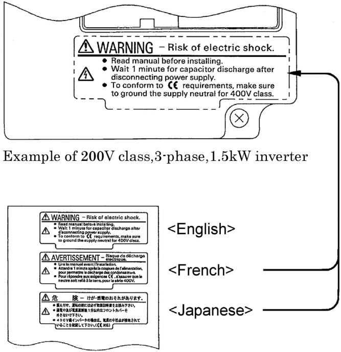
Japanese/French Warning Display
An English warning display is on the front panel of the inverter.
If you need Japanese or French warning display, use the stickers at the back of this manual.
Place it over the English warning display.
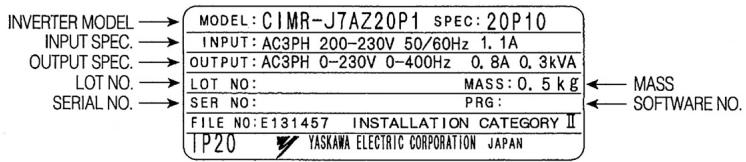
Checking the Name Plate
Example of 3-phase, 200VAC, 0.1kW (0.13HP)
Mounting
| CAUTION |
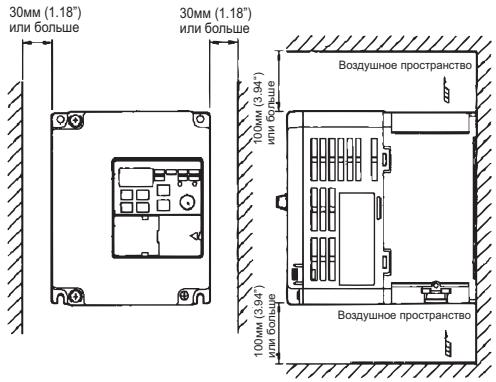
| · Lift the cabinet by the heatsink. When moving the Inverter, never lift it by the plastic case or the terminal covers. Otherwise, the main unit may fall and be damaged. · Mount the Inverter on nonflammable material (i.e., metal). Failure to observe this caution may result in a fire. · When mounting Inverters in an enclosure, install a fan or other cooling device to keep the intake air temperature below 122°F (50°C) for IP20 (open chassis type), or below 105°F(40°C) for NEMA1 (TYPE1). Overheating may cause a fire or damage the Inverter. · The VS mini generates heat. For effective cooling, mount it vertically. Refer to the figure in Mounting Dimensions on section 3. |

WARNING
- Only begin wiring after verifying that the power supply is turned OFF. Failure to observe this warning may result in an electric shock or a fire.
- Wiring should be performed only by qualified personnel.
- Failure to observe this warning may result in an electric shock or a fire.
- When wiring the emergency stop circuit, check the wiring thoroughly before operation. Failure to observe this warning may result in injury.
- Always ground the ground terminal according to the local grounding code. Failure to observe this warning may result in an electric shock or a fire.
- For 400V class, make sure to ground the supply neutral. Failure to observe this warning may result in an electric shock or a fire.
- If the power supply is turned ON during the FWD(or REV) RUN command is given, the motor will start automatically.
Turn the power supply ON after verifying that the RUN signal is OFF.
Failure to observe this warning may result in injury. - When the 3-wire sequence is set, do not make the wiring unless the multi-function input terminal parameter is set. Failure to observe this warning may result in injury.

CAUTION
- Verify that the Inverter rated voltage coincides with the AC power supply voltage. Failure to observe this caution may result in personal injury or a fire.
- Do not perform a withstand voltage test on the Inverter. Performing withstand voltage tests may damage semiconductor elements.
- To connect a Braking Resistor, Braking Resistor Unit, or Braking Unit, follow the Procedure described in this manual. Improper connection may cause a fire.
Always tighten terminal screws of the main circuit and the control circuits. Failure to observe this caution may result in a malfunction, damage or a fire. - Never connect the AC main circuit power supply to output terminals U/T1, V/T2 or W/T3. The Inverter will be damaged and the guarantee will be voided.
- Do not connect or disconnect wires or connectors while power is applied to the circuits. Failure to observe this caution may result in injury.
- Do not perform signal checks during operation. The machine or the Inverter may be damaged.
Preautions for wiring
Wiring the control circuit terminals
Screwdriver blade width
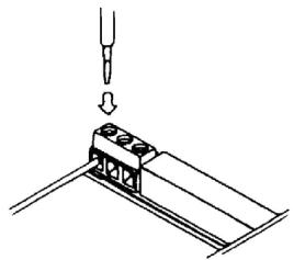
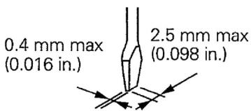
Insert the wire into the lower part of the terminal block and connect it tightly with a screwdriver.
5.5 mm
(0.22 in.) Wire sheath strip length must be 5.5mm (0.22in).

Operation
| WARNING |
| ·Only turn ON the input power supply after confirming the Digital Operator or blank cover(optional) are in place. Do not remove the Digital Operator or the covers while current is flowing. Failure to observe this warning may result in an electric shock. ·Never operate the Digital Operator or DIP the switches with wet hands. Failure to observe this warning may result in an electric shock. ·Never touch the terminals while current is flowing, even if the Inverter is stopping. Failure to observe this warning may result in an electric shock. ·When the fault retry function is selected, stand clear of the Inverter or the load. The Inverter may restart suddenly after stopping. (Construct the system to ensure safety, even if the Inverter should restart.) Failure to observe this warning may result in injury. ·When continuous operation after power recovery is selected, stand clear of the Inverter or the load. The Inverter may restart suddenly after stopping. (Construct the system to ensure safety, even if the Inverter should restart.) Failure to observe this warning may result in injury. ·The Digital Operator stop button can be disabled by a setting in the Inverter. Install a separate emergency stop switch. Failure to observe this warning may result in injury. |

WARNING
- If an alarm is reset with the operation signal ON, the Inverter will restart automatically. Reset an alarm only after verifying that the operation signal is OFF. Failure to observe this warning may result in injury.
- When the 3-wire sequence is set, do not make the wiring unless the multi-function input terminal parameter is set. Failure to observe this warning may result in injury.

CAUTION
- Never touch the heatsinks, which can be extremely hot.
Failure to observe this caution may result in harmful burns to the body.
- It is easy to change operation speed from low to high. Verify the safe working range of the motor and machine before operation.
Failure to observe this caution may result in injury and machine damage.
Install a holding brake separately if necessary.
Failure to observe this caution may result in injury.
- If using an Inverter with an elevator, take safety measures on the elevator to prevent the elevator from dropping.
Failure to observe this caution may result in injury.
- Do not perform signal checks during operation.
The machine or the Inverter may be damaged.
- All the constants set in the Inverter have been preset at the factory.
Do not change the settings unnecessarily.
The Inverter may be damaged.
Maintenance and Inspection
| WARNING |
| ·Never touch high-voltage terminals on the Inverter. Failure to observe this warning may result in an electrical shock. ·Disconnect all power before performing maintenance or inspection, and then wait at least one minute after the power supply is disconnected. Confirm that all indicators are OFF before proceeding. If the indicators are not OFF, the capacitors are still charged and can be dangerous. ·Do not perform withstand voltage test on any part of the VS mini. The Inverter is an electronic device that uses semiconductors, and is thus vulnerable to high voltage. ·Only authorized personnel should be permitted to perform maintenance, inspections, or parts replacement. (Remove all metal objects (watches, bracelets, etc.) before starting work.) Failure to observe these warnings may result in an electric shock. |
| CAUTION |
| ·The control PCB board employs CMOS ICs. Do not touch the CMOS elements. They are easily damaged by static electricity. ·Do not connect or disconnect wires, connectors, or the cooling fan while power is applied to the circuit. Failure to observe this caution may result in injury. |
Periodical Inspection
Periodically inspect the inverter as described the following table to prevent accidents and to ensure high performance with high-reliability.
| Location to check | Check for | Solution |
| Terminals, unit mounting screws, etc. | Connection hardware is properly seated and securely tightened. | Properly seat and tighten hardware. |
| Heatsink | Built up durst, and debris | Blow with dry compressed air: 39.2 x 10^4 to 58.8 x 10^4 Pa, 57 to 85 psi (4 to 6kg / cm^2) pressure. |
| Printed circuit board | Accumulation of conductive material or oil mist | Blow with dry compressed air: 39.2 x 10^4 to 58.8 x 10^4 Pa, 57 to 85 psi (4 to 6kg / cm^2) pressure If dust or oil cannot be removed, replace the inverter unit. |
| Power elements and smoothing capacitor | Abnormal odor or discoloration | Replace the inverter unit. |
| Cooling fan | Abnormal noise or vibration Cumulative operation time | Replace the cooling fan. |
Part Replacement
Inverter's maintenance periods are noted below. Keep them as reference.
Part Replacement Guidelines
| Part | Standard Replacement Period | Replacement Method |
| Cooling fan | 2 to 3 years | Replace with new part. |
| Smoothing capacitor | 5 years | Replace with new part. (Determine need by inspection.) |
| Breaker relays | - | Determine need by inspection. |
| Fuses | 10 years | Replace with new part. |
| Aluminium capacitors on PCBs | 5 years | Replace with new part. (Determine need by inspection.) |
Note: Usage conditions are as follows:
- Ambient temperature: Yearly average of 30^
- Load factor: 80% max.
- Operating rate: 12 hours max. per day
Others
| WARNING |
| ·Never modify the product. Failure to observe this warning can result in an electric shock or injury and will invalidate the guarantee. |
| CAUTION |
| ·Do not subject the Inverter to halogen gases, such as fluorine, chlorine, bromine, and iodine, at any time even during transportation or installation. Otherwise, the Inverter can be damaged or interior parts burnt. |
VS MINI J7
Quick Start Guide
- Wiring
- Control Circuit Terminals
- Installation
- Start up and Trial run
- Quick Parameter List
- Monitors
- Faults and Alarms
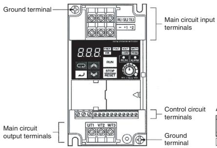
1. Wiring

Note 1: Connect single-phase 200 V AC to terminals R/L1 and S/L2 of the J7AZB
Note 2: The braking resistor cannot be connected because no braking transistor is incorporated.
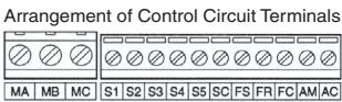
2. Control Circuit Terminals
| Symbol | Name | Function | Signal Level | |
| Input | S1 | Forward/Stop | Forward at ON/Stops at OFF | Photocoupler 8 mA at 24 V DC-1 |
| S2 | Multi-function Input 1 | Set by parameter n36 (Reverse/Stop)2 | ||
| S3 | Multi-function Input 2 | Set by parameter n37 (External Fault: NO)-2 | ||
| S4 | Multi-function Input 3 | Set by parameter n38 (Fault Reset)2 | ||
| S5 | Multi-function Input 4 | Set by parameter n39 (Multi-step reference 1)2 | ||
| SC | Sequence Input Common | Common for S1 through S5 | ||
| FS | Frequency Reference Power Supply | DC power supply for frequency reference use | 20 mA at 12 V DC | |
| FR | Frequency Reference Input | Input terminal for frequency reference use | 0 to 10 V DC (20 kΩ) | |
| FC | Frequency Reference Common | Common for frequency reference use | 4 to 20 mA0 to 20 mA | |
| Output | MA | Multi-function output: NO | Set by parameter n40 (during running)2 | Relay output 1 A max. at 30 V DC and 250 V AC |
| MB | Multi-function output: NC | |||
| MC | Multi-function output Common | Common for MA and MB use | ||
| AM | Analogue Monitor output | Set by parameter n44 (Output frequency)2 | 12 mA max. at 0 to 10 V DC | |
| AC | Analogue Monitor output Common | Common for AM use | ||
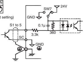
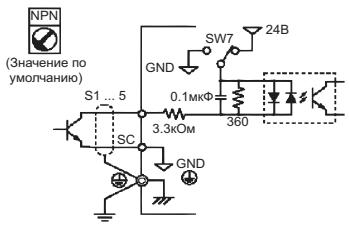
1 NPN is the setting for these terminals. No external power supply is required. Refer to connections shown below
2 Functions in parentheses are default settings.
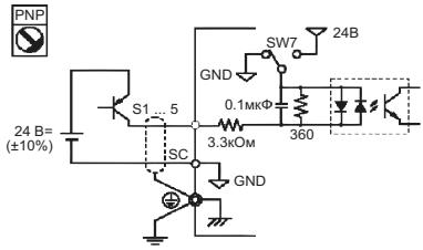
Selecting Input Method
Switches SW7and SW8, both of which are located above the control circuit terminals, are used for input method selection.
Remove the front cover and optional cover to use these switches.
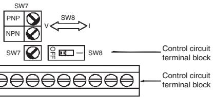
Selecting Sequence Input Method
By using SW7, NPN or PNP input can be selected as shown below

(Default setting)

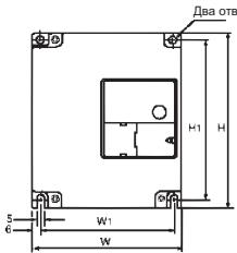
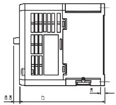
3. Installation
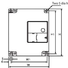
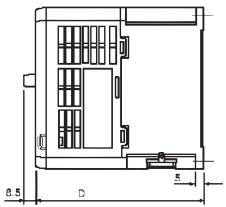
| Rated Voltage | Model J7AZ | Dimensions (mm) | Supply Recommendations | |||||
| W | H | D | W1 | H1 | MCCB (A) | Wire (mm2) | ||
| Three Phase 200 V AC | 20P1 | 68 | 128 | 70 | 56 | 118 | 5 | 2 |
| 20P2 | 68 | 128 | 70 | 56 | 118 | 5 | 2 | |
| 20P4 | 68 | 128 | 102 | 56 | 118 | 5 | 2 | |
| 20P7 | 68 | 128 | 122 | 56 | 118 | 10 | 2 | |
| 21P5 | 108 | 128 | 129 | 96 | 118 | 20 | 2 | |
| 22P2 | 108 | 128 | 154 | 96 | 118 | 20 | 3.5 | |
| 24P0 | 140 | 128 | 161 | 128 | 118 | 30 | 5.5 | |
| Single Phase 200 V AC | BOP1 | 68 | 128 | 70 | 56 | 118 | 5 | 2 |
| BOP2 | 68 | 128 | 70 | 56 | 118 | 5 | 2 | |
| BOP4 | 68 | 128 | 112 | 56 | 118 | 10 | 2 | |
| BOP7 | 108 | 128 | 129 | 96 | 118 | 20 | 3.5 | |
| B1P5 | 108 | 128 | 154 | 96 | 118 | 20 | 5.5 | |
| Three Phase 400 V AC | 40P2 | 108 | 128 | 81 | 96 | 118 | 5 | 2 |
| 40P4 | 108 | 128 | 99 | 96 | 118 | 5 | 2 | |
| 40P7 | 108 | 128 | 129 | 96 | 118 | 5 | 2 | |
| 41P5 | 108 | 128 | 154 | 96 | 118 | 10 | 2 | |
| 42P2 | 108 | 128 | 154 | 96 | 118 | 10 | 2 | |
| 43P0 | 140 | 128 | 161 | 128 | 118 | 20 | 2 | |
| 44P0 | 140 | 128 | 161 | 128 | 118 | 20 | 2 | |
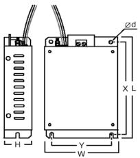
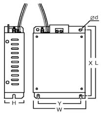
Noise Filter Specifications
| Model J7AZ | Filter 3G3JV- | Dimensions | |||||
| W | L | H | Y | X | d | ||
| 20P1 | PFI2010-SE | 82 | 194 | 50 | 92 | 181 | 5.3 |
| 20P2 | |||||||
| 20P4 | |||||||
| 20P7 | |||||||
| 21P5 | PFI2020-SE | 111 | 169 | 50 | 91 | 156 | 5.3 |
| 22P2 | |||||||
| 24P0 | PFI2030-SE | 144 | 174 | 50 | 120 | 161 | 5.3 |
| B0P1 | PFI1010-SE | 71 | 169 | 45 | 51 | 156 | 5.3 |
| B0P2 | |||||||
| B0P4 | |||||||
| B0P7 | PFI1020-SE | 111 | 169 | 50 | 91 | 156 | 5.3 |
| B1P5 | |||||||
| Model J7AZ | Filter 3G3JV- | Dimensions | |||||
| W | L | H | Y | X | d | ||
| 40P2 | PFI3005-SE | 111 | 169 | 50 | 91 | 156 | 5.3 |
| 40P4 | |||||||
| 40P7 | PFI3010-SE | 111 | 169 | 50 | 91 | 156 | 5.3 |
| 41P5 | |||||||
| 42P2 | |||||||
| 43P0 | PFI3020-SE | 144 | 174 | 50 | 120 | 161 | 5.3 |
| 44P0 | |||||||
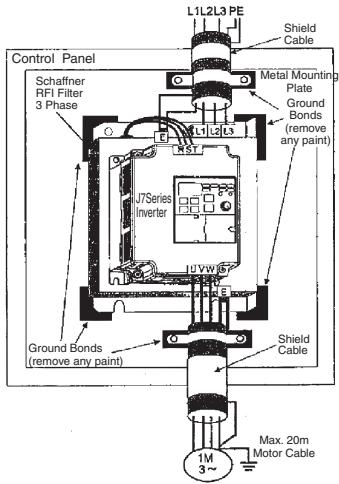
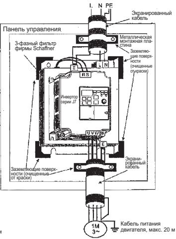
Installation of noise filter and J7
CIMR-J7□□□20P1 to 24P0
CIMR-J7□□□40P2 to 44P0
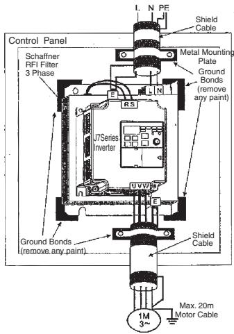
CIMR-J7□□□B0P1 to B4P0
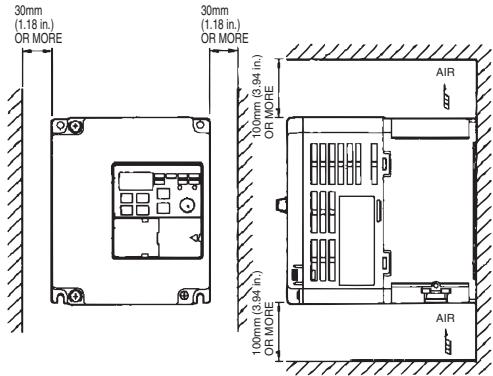
Mounting Dimensions
4. Start up and Trial run
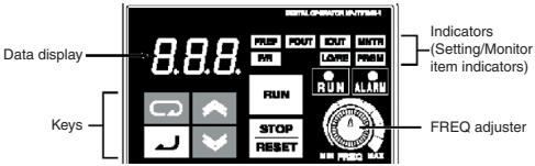
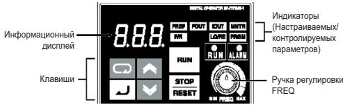
| Appearance | Name | Function |
| 888.88.88.88.88.88.88.88.88.88.88.88.88.88.88.88.88.88.88.88.88.88.88.88.88.88.88.88.88.88.88.88.88.88.0000000000000000000000000000000000000000000000000000000000000000000000000000000000000000000000000000 | Data display | Displays relevant data items, such as frequency reference, output frequency and parameter set values. |
| FREQ adjuster | Sets the frequency reference within a range between OHZ and the maximum frequency. | |
| FREF | FREF indicator | The frequency reference can b& monitored or set while this indicator is lit. |
| FOUT | FOUT indicator | The output frequency of the Inverter can be monitored or set while this indicator is lit. |
| IOUT | IOUT indicator | The output current of the inverter this indicator is lit. |
| MNTR | MNTR indicator | The values set in U01 through U10 are monitored while this indicator is lit. |
| F/R | F/R indicator | The direction of rotation can be selected while this indicator is lit when operating the Inverter with the RUN Key. |
| LOARE | LO/RE indicator | The operation of the Inverter through the Digital Operator or according to the sof parameters is selectable while this indicator is lit. Note: The status of this indicator can be only monitored while the Inverter is in operation. Any RUN command input is ignored while this indicator is lit. |
| PRGM | PRGM indicator | The parameter in n01 through to n79 can be set or monitored while this indicator is lit. Note: While the Inverter is in operation, the paramete can be only monitored and only some paramet can be changed. Any RUN command input is ignored while this indicator is lit. |
| Mode Key | Switches the setting and monitor item indicators in sequence. Parameter being set will be cancelled if this key is pressed before entering the setting. | |
| Increment Key | Increases multi-function monitor numbers, parameter num-bers and parameter set values. | |
| Decrement Key | Decreases multi-function monitor numbers, parametei numbers and parameter sel values. | |
| J | Enter Key | Enters multi-function monitor numbers, parameter numl and internal data values after they are set or changed. |
| RUN | RUN Key | Starts the Inverter running when the 3G3JV is in operation with the Digital Operator. |
| STOPRESET | STP/RESET Key | Stops the Inverter unless parameter nO6 is not set to disable the STOP Key. |
The following seven steps describe the recommended minimum operations to allow the J7 to control a connected motor in typical configuration, to allow simple operation in the quickest time:
Step 1 - initial checks
1-1 Checkpoints before connecting the power supply.
Check that the power supply is as of the correct voltage.
CIMR-J7AZ2□□□: Three phase 200 to 230VAC
CIMR-J7AZB□□□: Single phase 200 to 240VAC (Wire R/L1 and S/L2)
CIMR-J7AZ4□□□: Three phase 380 to 460VAC
1-2 Make sure that the motor output terminals (U/T1, V/T2, W/T3) are connected to the motor.
1-3 Ensure that the control circuit terminals and the control device are wired correctly.
1-4 Make sure that all control terminals are turned off.
1-5 Set the motor to no-load status (i.e. not connected to the mechanical system)
Step 2 - Connecting the power supply and check the display status
2-1 After conducting the checks in step-1, connect the power supply.
2-2 If the display is normal when the power is connected it will read as follows;
RUN indicator: flashes
ALARM indicator: off
Setting/monitor indicators: FREF, FOUT or IOUT is lit.
Data display: displays the corresponding data for the indicator that is lit.
When fault has occurred, the details of the fault will be displayed. In that case, refer to user's manual and take necessary action.
Step 3 - Initializing parameters
To initialize the drive parameters to factory defaults, set parameter n01 = 8 . This will set the J7 to accept start/stop commands in what is termed "2-wire control", i.e. 1 wire for a motor forward/stop command, and 1 wire for a motor reverse/stop command.
| KeySequence | Indicator | Displayexample | Explanation |
| FREF | 00 | Power On | |
| PRGM | n01 | Press the Mode Key repeatedly until the PRGM indicator is lit. | |
| PRGM | 1 | Press the Enter Key. The data of n01 will be displayed. | |
| PRGM | 8 | Use the Increment or Decrement Key to set n01 to 8. The display will flash. | |
| PRGM | 9 | Press the Enter Key so that the set value will be entered and the data display will be lit. | |
| In approximately1s. | PRGM | n01 | The parameter number will be displayed. |
Step 4 - Set the motor rated current
This parameter is used for the electronic thermal function for motor overload detection (OL1). By correctly setting this, the J7 will protect an overloaded motor from burning out.
Read the rated current (in amps) on the motor nameplate, and enter this into parameter n32. The example to the below shows entering a value of 1.8Amps.
| KeySequence | Indicator | Displayexample | Explanation |
| PRGM | n31 | Displays the parameter number | |
| PRGM | n32 | Use the Increment or Decrement Key until n32 is displayed. | |
| PRGM | n9 | Press the Enter Key. The data of n32 will be displayed. | |
| PRGM | n8 | Use the Increment or Decrement Key to set the rated motor current. The display will flash. | |
| PRGM | n8 | Press the Enter Key so that the set value will be entered and the data display will be lit. | |
| In approximately 1s. | PRGM | n32 | The parameter number will be displayed. |
Step 5 - Set the motor rated frequency
This is the maximum frequency the motor can run and allows the J7 to properly control the motor. Read the rated frequency (in Hz) on the motor nameplate, and enter this into parameters n09 and n11.
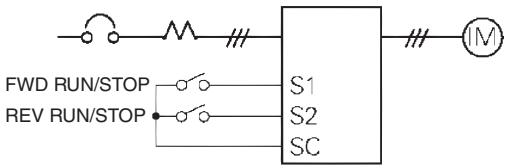
Step 6 - Set the operation command
This is the method for motor run and stop commands (i.e. how the inverter will start and stop the motor). The two basic operations are for the RUN and STOP/RESET keys on the Digital Operator, or for one of multi-function inputs through the control circuit terminals.
To set the operation command, enter the appropriate value into parameter n02:
0 = RUN and STOP/RESET keys on the Digital Operator are enabled.
1 = Multi-function inputs through the control circuit terminals.
The diagram to the below shows how to connect a switch to start/stop the motor in the forward direction in "2-wire control". Set parameter n02=1. To enable a separate switch for reverse rotation on control terminal S2, set parameter n36=2 (this is actually the factory default setting for n36).
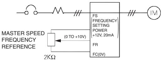
Step 7 - Set the frequency reference
This is the method for selecting the source for the motor speed command. The factory default is for the potentiometer on the digital Operator (FREF adjuster), in which case no setting is required.
Frequency reference can also come from an external potentiometer, an analog output from a PLC, or up to 8 pre-programmed speeds held in the inverter and selected via the multi-function inputs.
For example, to accept frequency reference from an external potentiometer, or a 0-10V analog output from a PLC, set parameter n03 = 2 .
- Quick Parameter List*1
| Parameter No. | Description | Range | Default |
| n01 | Parameter access:0: Limited parameter access1: Full parameter access8: Factory parameter initialise | 0 to 9 | 1 |
| n02 | Run command selection:0: Digital operator1: Control circuit terminal2: Communication (option) | 0 to 2 | 0 |
| n03 | Frequency reference selection:0: Digital operator (potentiometer)1: Frequency reference 1 (n21)2: Control circuit terminal (0 to 10V)3: Control circuit terminal (4 to 20mA)4: Control circuit terminal (0 to 20mA)6: Communication (option) | 0 to 4, 6 | 0 |
| n09 | Maximum output frequency | 50 to 400Hz | |
| n10 | Maximum output voltage | 1 to 255V (200V class)1 to 510V (400V class) | 200 (200V class)400 (400V class) |
| N11 | Maximum voltage output frequency | 50 to 400Hz | |
| n16 | Acceleration time 1 | 0.0 to 999sec | 10sec |
| n17 | Deceleration time 2 | 0.0 to 999sec | 10sec |
| n21 | Frequency reference 1 | 0.0 to 400Hz | 50Hz |
| n22 - n28 | Frequency reference 2 - 8 | 0.0 to 400Hz | 0Hz |
| n32 | Motor rated current | Depending on model | 0 to 120% of inverter rated output current |
| n36 - n39 | Multi-function input (S2 -S5) | 0 to 35 | -- |
| n40 | Multi-function output (MA-MB-MC) | 0 to 18 | 1 |
| n44 | Multi-function analog output (AM-AC):0: Output frequency (10V/Max, freq.)1: Output current (10V/Inverter rated current) | 0,1 | 0 |
| n46 | Carrier frequency | 1 to 4 (2.5 - 10kHz)7 to 9 (Proportional to output freq.) | Depending on model |
| n52 | DC injection braking current | 0 to 100% | 50% |
| n53 | DC injection braking at stop | 0 to 100% | 50% |
| n54 | DC injection braking at start | 0 to 100% | 50% |
| n55 | Stall prevention during deceleration:0: Enabled1: Disabled | 0,1 | 0 |
| Multi-function Inputs | Multi-function Outputs | ||
| Value*1 | Function | Value*1 | Function |
| 2 | Reverse/Stop | 0 | Fault Output |
| 3 | External Fault (NO) | 1 | During Run |
| 4 | External Fault (NC) | 2 | Frequency agree |
| 5 | Fault reset | 6 | Overtorque being monitored (NO) |
| 6 | Multi-step speed reference 1 | 12 | RUN mode |
| 7 | Multi-step speed reference 2 | 13 | Inverter ready |
| 8 | Multi-step speed reference 3 | 15 | Undervoltage in progress |
| 10 | Inching Command | Analogue Output Functionsts | |
| 12 | External base block (NO) | Value*1 | Function |
| 13 | External Base block (NC) | 0 | Otput frequency |
| 17 | Local/Remote selection | 1 | Output current |
*1 Refer to user's manual for full set value
Example of Parameter Settings

In approximately 1s.
| KeySequence | Indicator | Display example | Explanation |
| PREF | 00 | Power On | |
| PRGM | n01 | Press the Mode Key repeatedly until the PRGM indicator is lit. | |
| PRGM | n03 | Use the Increment or Decrement Key to set the parameter number. | |
| PRGM | 0 | Press the Enter Key. The data of the selected parameter number will be displayed. | |
| PRGM | 2 | Use the Increment or Decrement Key to set the data. At that time, the display will flash. | |
| PRGM | 2 | Press the Enter Key so that the set value will be entered and the data display will be lit (see note 1) | |
| In approximately 1s. | PRGM | n03 | The parameter number will be displayed. |
Note 1: To cancel the set value, press the Mode Key instead, The parameter number will be displayed.
2: There are parameters that cannot be changed while the Inverter is in operation. Refer to the list of parameters. When attempting to change such parameters, the data display will not change by pressing the Increment or Decrement Key.
6. Monitors
The Vs mini J7 allows you to monitor various conditions, such as output current and status of multifunction inputs.
This monitoring is performed via the "U" parameters.
| Key Sequence | Indicator | Display example | Explanation |
| FREP | 60 | Power On | |
| MNTR | U01 | Press the Mode Key repeatedly until the MNTR indicator is lit. U01 will be displayed. | |
| MNTR | U05 | Use the Increment or Decrement Key to select the monitor item to be displayed.. | |
| MNTR | 283 | Press the Enter Key so that the data of the selected monitor item will be displayed. | |
| MNTR | U05 | The monitor number display will appear again by pressing the mode key. |
| Constant No. | Name | Description | |
| U01 | Frequency Reference (FREF) | Hz | Frequency reference can be monitored. (Same as FREF) |
| U02 | Output frequency (FOUT) | Hz | Output frequency can be monitored. (Same as FOUT) |
| U03 | Output Current (IOUT) | A | Output current can be monitored. (Same as IOUT) |
| U04 | Output Voltage | V | Output voltage can be monitored |
| U05 | DC Voltage | V | Main circuit DC voltage can be monitored |
| U06 | Input Terminal Status | -- | Input terminal status of control circuit terminals can be monitored |
| U07 | Output Terminal Status | -- | Output terminal status of control circuit terminals can be monitored |
| U09 | Fault History | -- | Last four fault history is displayed |
| U10 | Software No. | -- | Software No. can be checked |
| U15 | Data Reception Error | -- | Contents of MEMOBUS communication data reception error can be checked. (contents of transmission register No. 003DH are the same) |
Input/Output terminal status
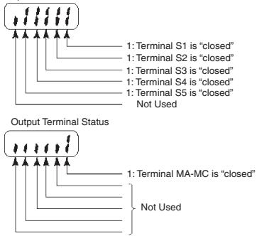
Input Terminal Status
7. Faults and Alarms
| Fault Display | Fault name and meaning | Possible cause and remedy |
| OC | Overcurrent | Check output for short circuit or ground fault. |
| Output current is higher than 250% of inverter rated current. | The Load is too large, reduce it ore use larger Inverter. Check motor FLA rating compared to inverter and V/F setting. | |
| OV | Overvoltage | Load inertia is too large and the motor is regenerating. |
| DC bus voltage has exceeded detection level. | Increase deceleration time (n020 or n022). Connect an external braking resistor and set n092 to 1. Check braking resistor and wiring. | |
| uV1 | Main circuit undervoltage | Check mains power supply voltage and connections. |
| DC bus voltage is below detection level. | Check correct supply for Inverter being used. Monitor for mains dips or interruptions. | |
| OH | Unit overheated | Refer to manual for installation guidelines and recommendations. |
| Temperature inside the inverter has exceeded 110°C. | Check cooling fan (if fitted). Check V/F characteristic ore reduce Carrier frequency. | |
| OL1 | Motor overload | Check and reduce the load. |
| The inverter is protecting the motor from overload based on an internal IT calculation using n036 setting. | Check V/F characteristic (Vmaxand Fmax). Increase the running speed of the motor. Increase acceleration/decelleration times. | |
| EF+1 | External fault | Check your control terminal wiring. |
| An external fault has been input. | A multi-functional digital input has been set to 3 or 4. Run signal must be removed before this can be reset. | |
| SER (flashing) | Sequence error | Inverter must be stopped when Local/Remote switching attempted. |
| Sequence input when inverter running. | Inverter must be stopped when Comms/Remote switching attempted | |
| bb (flashing) | External baseblock | Check your control terminal wiring. |
| An external baseblock command has been input. | A multi-functional digital input has been set to 12 or 13. | |
| EF (flashing) | Sequence error has occurred | Forward and reverse run signal have been applied simultaneously. |
*1 Refer to user's manual for full fault code listings
VS MINI J7
Kurzanleitung
IЯь blybopa cnocoba BvOda DnckpeTbIx CrrHAnoPnpdHa3NaHeBn pepeKlnOaTeiN SW7 n SW8, pacnoJooKeHbIe had kJIemMaMm cXeMb yUnpaBHeNIA.
TcBbI pOyHHT BDCTyI K 3TM NpeKIOuYaTeTlA, Heo6xDMIO CHrTpeNDHO IdoONHNTBHyU KpUkIs.
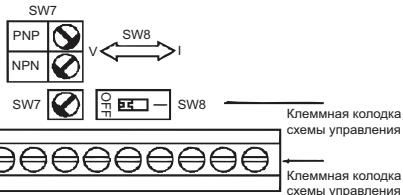
Bb6op cnocoba BBOda nckpeThbIX CnHAnOB
C nomoio nepeknioatea SW7 moKHO bIbpaT tIN dNcKeTHbX BXoOB (NPN uIN PNP).
3. MoHTax
| HOMINAHLBHe HANPRJXENHe | Mодь J7AZ | Размеры (MM) | Рекомен dyeчебу НOMINAJI | Побов (MM²) | ||||
| W | H | D | W1 | H1 | MCCB (A) | |||
| 200 B~3-фанhoe | 20P1 | 68 | 128 | 70 | 56 | 118 | 5 | 2 |
| 20P2 | 68 | 128 | 70 | 56 | 118 | 5 | 2 | |
| 20P4 | 68 | 128 | 102 | 56 | 118 | 5 | 2 | |
| 20P7 | 68 | 128 | 122 | 56 | 118 | 10 | 2 | |
| 21P5 | 108 | 128 | 129 | 96 | 118 | 20 | 2 | |
| 22P2 | 108 | 128 | 154 | 96 | 118 | 20 | 3.5 | |
| 24P0 | 140 | 128 | 161 | 128 | 118 | 30 | 5.5 | |
| 200 B~1-фанhoe | BOP1 | 68 | 128 | 70 | 56 | 118 | 5 | 2 |
| BOP2 | 68 | 128 | 70 | 56 | 118 | 5 | 2 | |
| BOP4 | 68 | 128 | 112 | 56 | 118 | 10 | 2 | |
| BOP7 | 108 | 128 | 129 | 96 | 118 | 20 | 3.5 | |
| B1P5 | 108 | 128 | 154 | 96 | 118 | 20 | 5.5 | |
| 400 B~3-фанhoe | 40P2 | 108 | 128 | 81 | 96 | 118 | 5 | 2 |
| 40P4 | 108 | 128 | 99 | 96 | 118 | 5 | 2 | |
| 40P7 | 108 | 128 | 129 | 96 | 118 | 5 | 2 | |
| 41P5 | 108 | 128 | 154 | 96 | 118 | 10 | 2 | |
| 42P2 | 108 | 128 | 154 | 96 | 118 | 10 | 2 | |
| 43P0 | 140 | 128 | 161 | 128 | 118 | 20 | 2 | |
| 44P0 | 140 | 128 | 161 | 128 | 118 | 20 | 2 | |
PpmeaHHe: MCCB = ABtOMaTnueckn BbIKNIOaTeJIb B IITOM KOpnyce.
TexHnueckne xapaKTepeNtKnФиЛьТра NOДaВлЕнЯ NOMEX
| Модан J7AZ | Фильтр 3G3JV- | РаЗмеры | |||||
| W | L | H | Y | X | d | ||
| 20P1 | PFI2010-SE | 82 | 194 | 50 | 92 | 181 | 5.3 |
| 20P2 | |||||||
| 20P4 | |||||||
| 20P7 | |||||||
| 21P5 | PFI2020-SE | 111 | 169 | 50 | 91 | 156 | 5.3 |
| 22P2 | |||||||
| 24P0 | PFI2030-SE | 144 | 174 | 50 | 120 | 161 | 5.3 |
| BOP1 | PFI1010-SE | 71 | 169 | 45 | 51 | 156 | 5.3 |
| BOP2 | |||||||
| BOP4 | |||||||
| BOP7 | PFI1020-SE | 111 | 169 | 50 | 91 | 156 | 5.3 |
| B1P5 | |||||||
| Модан Л7AZ | Фильтpr 3G3JV- | РаЗмеры | |||||
| W | L | H | Y | X | d | ||
| 40P2 | PFI3005-SE | 111 | 169 | 50 | 91 | 156 | 5.3 |
| 40P4 | |||||||
| 40P7 | PFI3010-SE | 111 | 169 | 50 | 91 | 156 | 5.3 |
| 41P5 | |||||||
| 42P2 | |||||||
| 43P0 | PFI3020-SE | 144 | 174 | 50 | 120 | 161 | 5.3 |
| 44P0 | |||||||
CIMR-J7□□□40P2...44P0
CIMR-J7□□□B0P1 ... B4P0
MoHTaXHbIe pa3Mepbl
4.Пробнызануск
6. KoHTpOJIpyeMbIe npaMeTpbl
B INHEPTope VS J mini 7J nepdycoMTpeha BO3MOXHOCTbKTOPOPA3aNINHbIX napaMeTPOB, hnapIMPEB, bIbXoHORO TOKA iNcOTOHAR MHORODYHKUHOHAfHBxix BXODOG.
Дя КОНТРОЯ рашичнынnapametpoB npedha3haeHy npamaTepbI rpynnb "U".
For the Middle East, Africa and other countries in Eastern Europe, Tel: +31 (0) 23568 13 00 www.europe.omron.com
Manufacturer

In the event that the end user of this product is to be the military and said product is to be employed in any weapons systems or the manufacture thereof, the export will fall under the relevant regulations as stipulated in the Foreign Exchange and Foreign Trade Regulations. Therefore, to be sure to follow all procedures and submit all required documents for the export, the foreign government shall not allow the export of the products. Specifications are subject to change without notice for ongoing product modifications and improvements.
2003 OMRON Yaskawa Motion Control. All rights reserved.
Note: Specifications subject to change without notice.
Manual No.139E-EN-01