GWUP180 - Roller shutter motorization CHAMBERLAIN - Free user manual and instructions
Find the device manual for free GWUP180 CHAMBERLAIN in PDF.

User questions about GWUP180 CHAMBERLAIN
0 question about this device. Answer the ones you know or ask your own.
Ask a new question about this device
Download the instructions for your Roller shutter motorization in PDF format for free! Find your manual GWUP180 - CHAMBERLAIN and take your electronic device back in hand. On this page are published all the documents necessary for the use of your device. GWUP180 by CHAMBERLAIN.
USER MANUAL GWUP180 CHAMBERLAIN
AT/BA/BE/BG/CH/CY/CZ/DE/DK/ES/
FR/GB/GR/HR/HU/IE/IS/IT/LU/MT/NL/
NO/PL/PT/RO/RU/SE/SI/SK/TR/YU
ACHTUNG
PLEASE START BY READING THESE IMPORTANT SAFETY RULES - SAVE THESE INSTRUCTIONS

Such warning signs mean "take care!" They require that you pay attention if personal injury and/or material damage is/are to be avoided. Please read these warnings carefully. This motor has been designed and tested in such a way as to ensure optimum safety of installation and use provided the following safety instructions are followed completely. Non-compliance of the following safety instructions can result in serious personal injury and/or material damage.

Please read these installation instructions carefully in order to avoid errors and to ensure the flawless operation of the shutter strap motor.

Any electrical work that may be necessary should only be carried out by a qualified electrician.

Examine the shutter strap motor prior to installation to ensure it is undamaged. A clean, undamaged and flexible strap is a prerequisite enabling the motor to perform optimally. The use of defective equipment can result in personal injury and/or material damage.

The shutter strap motor is only deemed to be operational when it has been installed and located in a closed housing.

Only use the shutter strap motor in a dry environment together with the original accessories (light sensor, large strap spool).

When connecting the equipment to the main supply, please ensure the main plug is accessible at all time.
Access to it should not be blocked by cabinet or similar.

The shutter strap motor is compatible with all built-in winding assemblies with hole pitches of 10.5 / 13.5 / 16.5 and 18,5cm. Suitable for all strap widths up to max. 23mm.

For shutters with mini plastic sections approx. 6.0m^2 with mini aluminum sections approx. 4.5m^2 with maxi plastic sections approx. 4.5m^2 and maxi aluminum sections approx. 2.6m^2 .

Please keep your receipt of purchase and these installation instructions in a safe place. Should you need to make use of your warranty entitlement, please submit the receipt together with the item concerned.

In order to avoid damage to the shutter installation during initial set up, the shutter strap must be wrapped around the strap spool at least twice when the shutter is open.
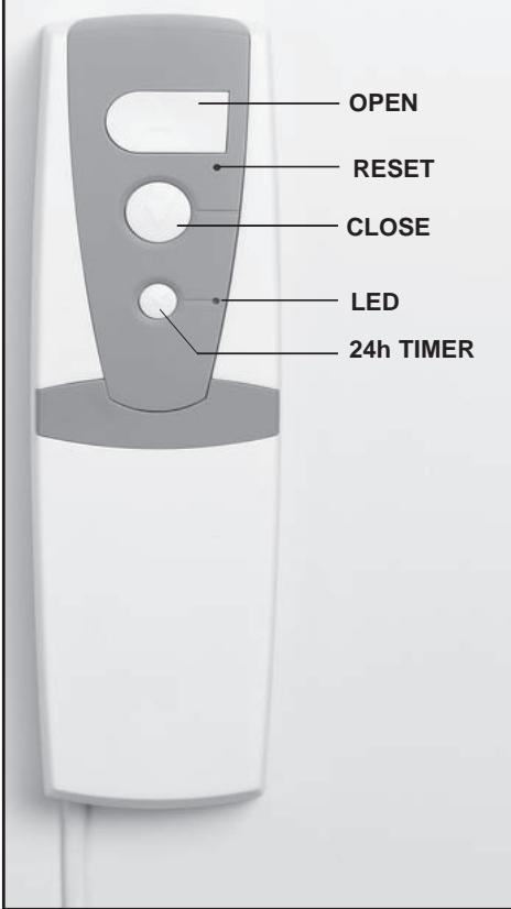
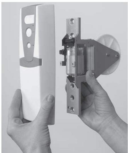
Control panel description:
Included in delivery:
-
A two part electric strap coiler consisting of 1x flush mount coiler 1x control panel to be assembled incl. plug and 1.5m of power cable (no fig.)
-
Operating instructions (no fig.)
Hardware required:
- Scissors
- Screw driver
INSTALLATION:

The motor replaces mechanical flush mount strap coils with strap widths from 16mm up to max. 23mm.

Permitted strap length is max. 4.5m with a strap thickness of 1.3mm. (The large strap spool, available as accessory, allows a strap length of 10m).

For shutters (without mechanical gear) with plastic framing up to approx. 6m^2

Check shutter construction regarding proper operation. The shutter must open and close easily when used manually. The strap must not be frayed; the shutter must not be wedged. Exchange defective parts.

Max. shutter size (shutter size = length x width):
Plastic-Mini-Profiles approx. 6m^2
Aluminium-Mini-Profiles approx. 4.5m^2
Plastic-Maxi-Profiles approx. 4.5m^2
Aluminium-Maxi-Profiles approx. 2.6m^2
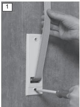
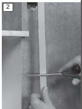
First completely close the shutter. Remove the fastening screws of the facing on the wall using a screw driver (fig.1) and store screws for later reuse. Pull the mechanical strap coiler out of the wall (Attention: the spring from the mechanical strap coiler may shoot back uncontrollably!). Block the spring casing with a metal flap. Extract the strap and cut it approx. 30cm beneath the opening in the wall (fig.2).
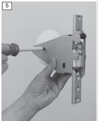
Now take the shutter strap motor and remove the screw cover on the front (fig.3). Remove the two unlosable screws and take the control panel off the flush mount coiler (fig.4). Loosen the fastening screw of the strap spool holder using a screw driver (fig.5). Slowly remove the strap spool and remove the sleeve from the centre of the spool.


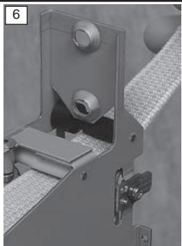
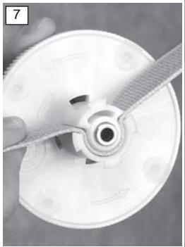
Now insert the strap from the front into the flush mount coiler first underneath the black reel and then underneath the white reel within (fig.6). Extract the strap about 30cm on the other side. Pay attention towards the strap not being twisted at any point from exiting the wall up to the flush mount coiler. Insert the strap as shown into the spool. The strap ending should protrude approx. 3cm (fig.7).
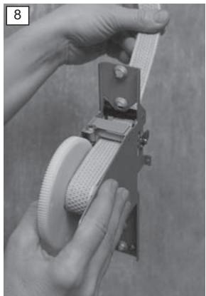
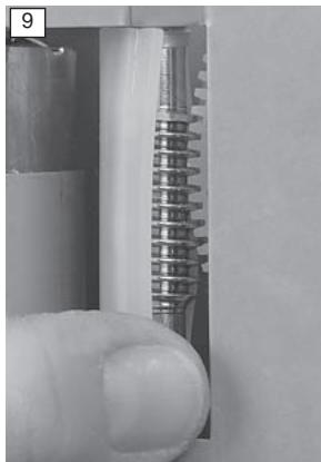
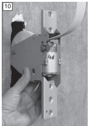
Reinsert the sleeve into the spool. Reinstall the spool into the flush mount coiler and check correct fitting: the cogs on the edge of the spool reach into the vertical drive shaft (fig.8+9). Insert the extracted screw back into the fastening of the spool and fasten using a screw driver. Slide the flush mount coiler into the opening in the wall and readjust it with the screws from the original facing (fig. 10+11).
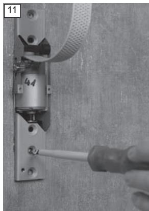
Pay attention towards the secure grip of the screws.
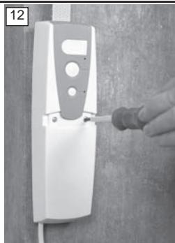
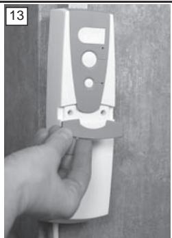
Put the control panel back on the flush mount coiler and tighten both of the unlosable screws back into their sockets using a screw driver. Reinsert the screw cover (fig. 12+13). Now put the plug into the socket. The installation of the shutter strap motor is complete.
The strap coiler may also be connected directly the mains supply (p.3).
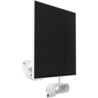
Installation of light sensor GWLS1 (accessory):
A light sensor incl. plug and approx. 1.3m of power cable are separately available.
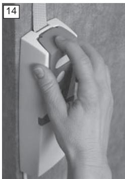
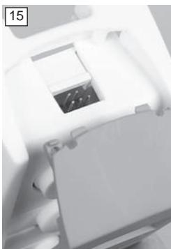
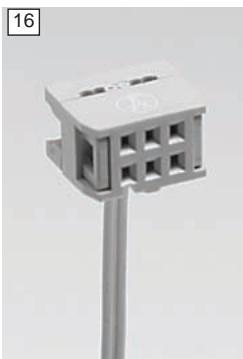
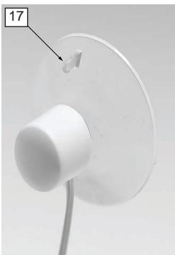
In order to install the light sensor press down lightly on the grey cover of the control panel and pull it back towards you (fig.14). Carefully put the plug of the light sensor on the six pins provided for in the middle (fig 15+16); the cable must be showing towards the wall. Slide the grey cover back onto the control panel. The light sensor cable may extrude from the cover either through the left- or right-hand carving in the cover. Clean the window pane and position the light sensor onto the window pane as desired. Information: The shutter strap motor will close the shutter after 15min of direct sunlight to the position of the light sensor. In order to open/close shutter again, press corresponding button on the control panel; this may also be achieved by activated timer control. To remove or relocate the light sensor only pull on the small plug (fig.17) of the transparent suction cup. Pulling/Pushing the white plastic top may lead to destruction of light sensor.
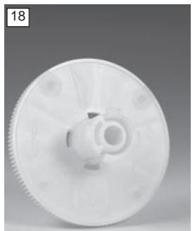
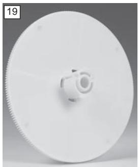
The following spare parts are available:
041AGW45 strap spool for strap lengths up to 4.5m (fig.18)
041AGW10 large strap spool for strap lengths up to 10m (fig.19)
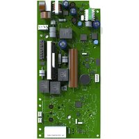
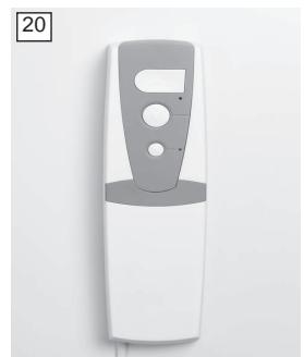
041AGW01 removable control panel (fig.20)
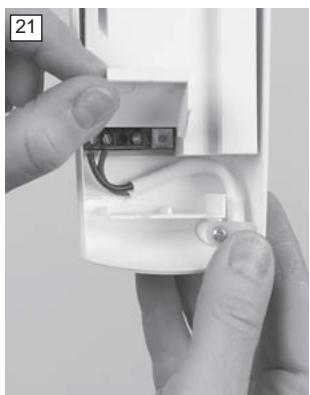
Direct connection to mains supply (optional):
Attention: This work should be done by a skilled worker! Pull plug before opening!
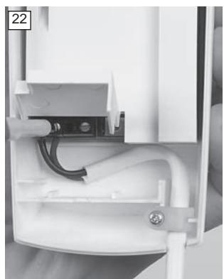
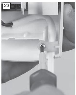
The shutter strap motor may be connected directly to the mains supply. Open the cover at the back of the control panel using a tool, e.g. a screw driver (fig.21). Loosen both screws of the connection clamp with a screw driver (fig.22). Now remove the screw of the strain relief and extract the cable. Now put the phase- and neutral-wire of the mains in both of the left clamps (random order) and reinsert both of the clamp screws. Put the cable back into the strain relief and tighten screw again using a screw driver (fig.23).
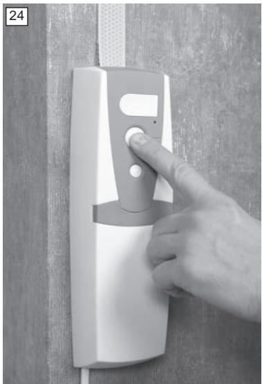
Initial set up:
Make sure that shutter can move freely. Obstacles, e.g. flowerpots on the outer window-sill, are to be removed. Make sure that stoppers/conical stops are existent and that these have a firm connection with the shutter. Now push any one of the three buttons of the shutter strap motor (fig.24). In the following the window size is automatically measured, i.e. defining of upper- and lowermost limit. The shutter strap motor will pull the shutter up until the conical stops reach the shutter box (or wall). A humming sound indicates the correct functioning of the motor.
Then the shutter will be lowered automatically until completely closed and the lower limit is defined. Finally the shutter will be opened again automatically and will stop shortly before reaching upper limit. Attention: The automatical measuring cannot be interrupted. Should this process be interrupted through power failure or should the plug be pulled accidentally, start over again = push any one of the three buttons.
After completing this process the initial set up is finished. The shutter can be opened or closed by pushing the Open- or Close-button ( fig.24).
Safety function:
If obstacle is hit or shutter profiles are tilted the GWUP180 will shut down automatically. This avoids personal or property damage.
Continue with Timer Control if automatic opening/closing is desired.
Timer Control:
In order to program the timer control briefly push (max. 2sec) first lowermost button "P" then Open/Close-button.
Example:
Push button "P" at 7am. The LED will start flashing. Then briefly push Open-/Close-button; the shutter will move to the upper limit and the LED will glow.
Daily opening is now pre-programmed to 7am.
Push button "P" at 8pm. The LED will start flashing. Then briefly push Open-/Close-button; the shutter will move to the lower limit and the LED will glow.
Daily closing is now pre-programmed to 8pm.
Deactivating / Activating / Changing timer control:
Deactivating - Briefly push button "P" (max. 2sec). Timer control is deactivated, the pre-programmed times remain stored. LED will flash for approx. 5sec and will then stop flashing.
Activating - By pushing button "P" again (max. 2sec) the shutter will open/close at pre-programmed times. LED will flash for approx. 5sec and will the stay on.
Changing - Programming at desired times as described under Timer Control. Pre-programmed times will be overwritten.
Adjusting / Deleting / Changing additional positioning:
Adjusting
Keep pushing Open-/Close-button until shutter is in desired position
Then push button "P" until LED stops flashing
The additional position is programmed
Deleting
Keep pushing Open-/Close-button; the shutter will open or close completely
As soon as upper/lower limit is reached shutter will stop moving
Now push button "P" until LED stops flashing
The additional position is deleted
Changing
See Adjusting
Pre-programmed additional positioning will be overwritten
Reset (delete all settings):
Push the Reset-button using a pointed device, e.g. ballpoint pen (see control panel description). All previously pre-programmed settings will be deleted. The motor is back to its factory setting. Pushing any one of the white buttons on the control panel will lead to new initial set up / measuring of window size.
Removal of motor:
- Close shutter completely.
- Cut motor off from power supply, if necessary remove light sensor from window
- Remove screw cover from front of control panel and unscrew both of the unlosable screws. Lift control panel off.
- Now remove both of the fastening screws of the flush mount coiler using a screw driver and extract coiler from out of the wall.
- Loosen the fastening screw of the strap spool holder. Slowly remove strap spool and take the sleeve out from the centre of the spool.
- Now remove the strap from the spool and pull it out of the flush mount coiler.
Available accessories:
If necessary a shutter strap coiler can be used with a strap length of up to 10m. The large strap spool N° 041AGW10 with a diameter of 14.5cm will be necessary. Please be aware that the shutter strap coiler equipped with this strap spool only fits into the flush mount strap box which has a distance between screws of 185mm. Therefore check existing installation.
Technical data:
Item N°: GWUP180
Supply voltage: 230V AC / 50Hz
Operating voltage: 24V
Pulling force approx. 18kg / 180N
Torque: 1.8Nm
Operating power: max 60W
Standby: <0.2W
Strap width: >23mm
Strap capacity approx. 4.5m with strap thickness of 1.3mm (approx. 10m with available large strap spool)
Short time rating: max 5min
Protection class II (only use in dry areas)
Power cable H05 VV-F 2 x 0.75
Material recyclable
Tested according to EN 60335
Certificates LGA/GS, CE
FAQ's:
- Motor does not work.
Power supply is interrupted.
Check cable connection between motor and socket.
Check if there is a power failure.
- Shutter does not close.
There is a malfunction of shutter installation.
Check entire equipment and remove the malfunction.
Pay special attention to:
- Dislocated lamella - because not locked into sideways position
- Sideways locking of lamella - due to damage
- Funnel-guides at upper end of rails
In order to do this cover of shutter box may have to be opened. (Note: according to DIN 18073 shutter box lid must be easily accessible and removable).
- Shutter is not heavy enough.
Weigh it down, e.g. insert suitable flat bar into the lowest lamella. - Shutter does not stop at programmed limits.
Strap is overstretched.
Do a reset.
- Programmed times are shifted.
Possible cause:
(brief) power failure
- Internal clock stopped. Programmed times are consequently shifted. Readjust timer control (see p.4)
- Humming sound when under heavy load.
Load is larger than 180N / 18kg. Make sure that shutter is not stuck. Check the pulling weight by using the strap and with the aid of mechanical scales. When pulling at the strap the weight shown on the scales will lessen by the force needed to move the strap. The difference between your body weight and the measured value when pulling the strap must not exceed 18kg.
ATTENTIE
BELANGRIJKE INSTRUCTIES VOOR MONTAGE EN GEBRUIK
BEGIN MET HET LEZE VAN DEZE BELANGRIJKE VEILIGHEIDSINSTRUCTIES

Reset (borrar todos los ajustes):
Chamberlain GmbH warrants to the first retail purchaser of this product that the product shall be free from any defect in materials and/or workmanship for a period of 24 full months (2 years) from the date of purchase. Upon receipt of the product, the first retail purchaser is under obligation to check the product for any visible defects. Conditions: The warranty is strictly limited to the reparation or replacement of the parts of this product which are found to be defective and does not cover the costs or risks of transportation of the defective parts or product. This warranty does not cover non-defect damage caused by unreasonable use (including use not in complete accordance with Chamberlain's instructions for installation, operation and care; failure to provide necessary maintenance and adjustment; or any adaptations of or alterations to the products), labor charges for dismantling or reinstalling of a repaired or replaced unit or replacement batteries. A product under warranty which is determined to be defective in materials and/or workmanship will be repaired or replaced (at Chamberlain's option) at no cost to the owner for the repair and/or replacement parts and/or product. Defective parts will be repaired or replaced with new or factory rebuilt parts at Chamberlain's option. If, during the warranty period, the product appears as though it may be defective, contact your original place of purchase. This warranty does not affect the purchaser's statutory rights under applicable national legislation in force nor the purchaser's rights against the retailer arising from their sales/purchase contract. In the absence of applicable national or EU legislation, this warranty will be the purchaser's sole and exclusive remedy, and neither Chamberlain nor its affiliates or distributors shall be liable for any incidental or consequential damages for any express or implied warranty relating to this product. No representative or person is authorized to assume for Chamberlain any other liability in connection with the sale of this product.
GARANTIE VOOR ROLLUIKBANDAANDRIJVING
Manager, Regulatory Affairs