
KH 1150 CEILING FAN WITH HALOGEN LIGHTING - Ceiling fan with light LERVIA - Free user manual and instructions
Find the device manual for free KH 1150 CEILING FAN WITH HALOGEN LIGHTING LERVIA in PDF.

User questions about KH 1150 CEILING FAN WITH HALOGEN LIGHTING LERVIA
0 question about this device. Answer the ones you know or ask your own.
Ask a new question about this device
Download the instructions for your Ceiling fan with light in PDF format for free! Find your manual KH 1150 CEILING FAN WITH HALOGEN LIGHTING - LERVIA and take your electronic device back in hand. On this page are published all the documents necessary for the use of your device. KH 1150 CEILING FAN WITH HALOGEN LIGHTING by LERVIA.
USER MANUAL KH 1150 CEILING FAN WITH HALOGEN LIGHTING LERVIA
6.1Assembling theblade holders (J) 3
6.2 Installing the Extension Rod (B) 3
6.3 Installing the Light Module (E) 4
6.4 Removing the Transport Protection 4
6.5 Installing the Blades (H) 4
6.6 Hanging the Fan 4
7 Operation 6
7.1 Setting the Speed 6
7.2 Setting the Direction 6
8 Cleaning 6
9 Technical data 6
10Items supplied 6
11 Troubleshooting 7
12 Garantie und Service 8
13Importer 8
14 Disposal 8
Read these operating instructions carefully before using the appliance for the first time and preserve this booklet for future reference. Pass this booklet on to whoever might acquire the appliance at a later date.
IMPORTANT:
Always comply with the safety instructions!
Study the instructions for installation and use before starting to work with the fan.
Danger:
Always comply with the safety instructions detailed below. Otherwise, there is a significant risk of accidents.
Danger of electric shock
- Only a qualified electrician may connect the device to a properly installed and earthed power line with a mains voltage from 220 to 240V at 50Hz .

Never submerge the appliance in liquid, never subject it to moisture and never use it outdoors. Should liquid nevertheless enter the device housing, disconnect the device from the power source, for instance by removing the associated building fuse or switching the corresponding circuit breaker (off position) in the fuse box.
- Do not kink or crush the power cable.
- If the power cable or the device housing are damaged, you must have the device repaired by a specialist before using it again. You may not open the device housing. If you do, the device is no longer safe and the warranty is voided.
Risk of fire
- Do not leave the appliance unattended when in use.
- Never hang the device in the vicinity of heat sources.
- Do not connect the ceiling fan through a dimmer switch. Use only the pull chain provided for changing the rotation speed.
Injury hazard
- This appliance is not intended for use by individuals (including children) with restricted physical, physiological or intellectual abilities or deficiencies in experience and/or knowledge unless they are supervised by a person responsible for their safety or receive from this person instruction in how the appliance is to be used.
- Children should be supervised to ensure that they do not play with the appliance.
- The minimum distance from the tips of the blades to the floor must be 2.30m when installed. The distance between the blades and the ceiling must be at least 0.30m . The side distance to room walls or obstructions must be at least 0.60m (see Fig. 1).
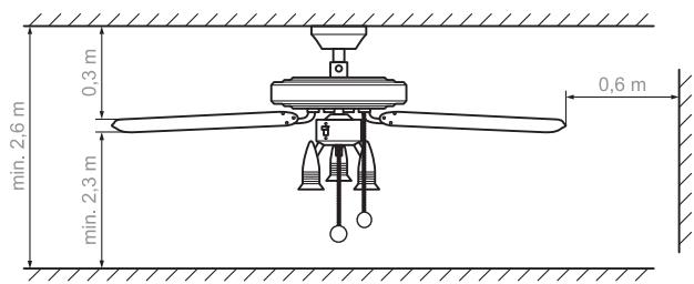
Fig. 1: Minimum distances for the ceiling fan
- No obstructions may be located within the rotation range of the device.
- The device must be securely fastened to the room ceiling. The ceiling, pins and screws must be capable of supporting the additional load produced by the rotation of the device. If necessary, seek advice at a building supplies store regarding the mounting of the ceiling fan.
Risk of choking
- The device may not be operated in combination with an oil or gas oven or heater. Exception: the smoke outlet has been inspected and approved by an expert in consideration of the fan operation.
2 Proper Use
The ceiling fan serves exclusively for promoting circulation. This ceiling fan is intended exclusively for use in private households. Observe all information in this installation and operating manual, in particular the safety instructions. Any other use is considered improper use.
3 Product Overview
A Casing
B Extension rod (2 variants)
C Connector
D Sliding switch for changing the direction
E Light module with 3 bulbs (incl. 3 halogen light bulbs)
F Pull chain for the light
G Pull chain for changing the speed
H Blades (5 pcs.)
Blade attachment (5 pcs.)
J Blade mount (5 pcs.)
K Motor housing
L Installation plate
4 Product Description
The Kompernaß KH 1150 ceiling fan has three speed levels that are controlled with the pull chain. The direction can be changed with a switch, allowing the fan to blow air downward or draw it up. In addition, the fan is equipped with a light with 3 halogen bulbs; the light is switched on and off with a separate pull chain.
5 Guide
Section 6 describes the installation and Section 7 describes the basic operation of the KH 1150 ceiling fan.
Read these sections carefully in order to perform the installation quickly and properly and to understand all the functions of the fan.
The following signal words and symbols are used:
DANGER
Warns against possibly serious or fatal injuries
Warning!
Warns against possible minor injuries or possible material damage
Caution
Warns against possible defects or destruction of the product
IMPORTANT/NOTE
Provides important or useful information
Warning:
Follow the safety instructions (see Section 1) to avoid injuries or damage as a result of installation errors. Do not use the fan if it is damaged.
① NOTE:
The letters in parentheses refer to the figure in Section 3
"Product Overview".
Required Tools
Phillips head screwdriver
Open-jawed spanner 8 mm
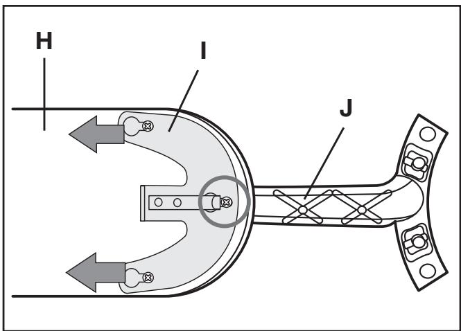
6.1 Assembling the blade holders (J)
1 Select the desired decor: wood grain or white surface. Lay out the blades so that the desired decor faces down.
2 Run the lock pins of a blade mount (J) through the 3 openings of a blade (H) from below. Position the blade attachment (I) and push in the direction of the arrow (see Fig.). The spring clip must snap in and secure the middle pin (see Fig.: circle). Mount all blades in the same way.
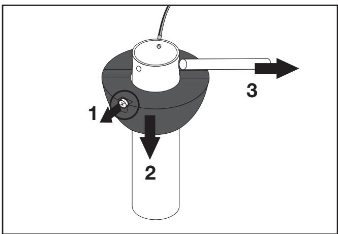
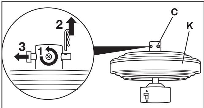
6.2 Installing the Extension Rod (B)
1a Long rod with plastic mount:
Step 1: Loosen the side locking pin on the extension rod (see Fig., circle).
Step 2: Slide the mount downward until the lock pin is exposed.
Step 3: Pull out the lock pin.
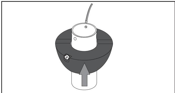
1b If you would like to use the short extension rod, pull the mount entirely off the long rod and slide it about halfway onto the short rod, as shown.
2 Step 1: Loosen the side screws of the connector (C) so that the extension rod can be inserted.
Step 2: Remove the pins of the connector: Pull out the linch pin.
Step 3: Remove the pin.
DANGER:
Damaged cables lead to short-circuits. In such cases, touching the fan could be life-threatening!
During the following insertion do not damage the bolts in the extension rods and the cable connection piece!
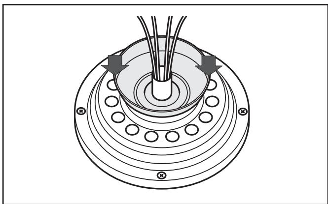
3 Pull the cable through the casing and place the casing onto the motor housing over the connector.
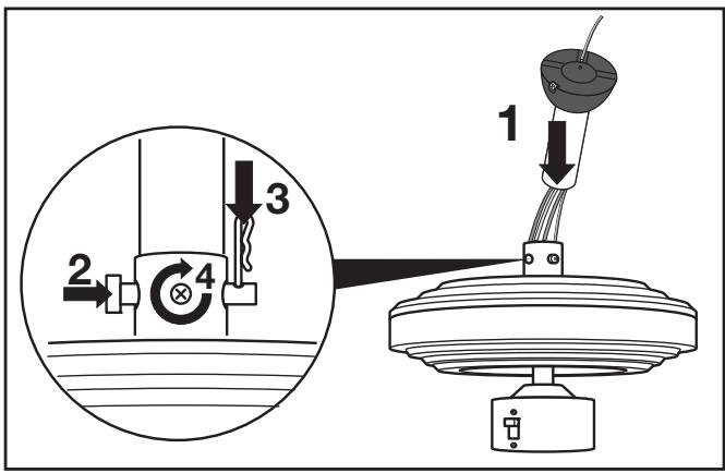
4a Step 1: Longer extension rod: Pull the cable through, then insert the extension rod into the connection piece.
Step 2: Install the safety bolt on the connecting piece.
Step 3: Insert the linch pin.
Step 4: First tighten both screws evenly at the same time until hand-tight, then screw them in tightly with the screwdriver. Turn the nuts firmly against the connecting piece (counter).
4b Installing the short Extension Rod: After pulling the cable through (s. 4a, part-step 1) you must first carry out the following assembly step 5. Afterwards, carry out the part-steps 2 to 4 under 4a.
5 Guide the bolts through the upper openings of the extension rod and align them in the middle.
Push the support upwards over the bolts, thereby ensure that the safety screw fits into the appropriate recess. (cf. Fig. Step 1a). Screw the safety screw into the thread of the extension rod.
6.3 Installing the Light Module (E)
DANGER:
Damaged cables lead to short-circuits. In such cases, touching the fan could be life-threatening!
Position the cable in the housing such that it will not be squeezed when inserting the light module!
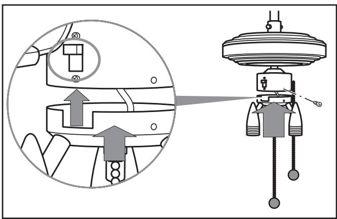
1 Remove the three screws with lock washers from the light module (E).
2 Connect the cable plug for the light modul to the socket on the fan.
3 Insert the light module into the motor housing, making certain that the recess is located under the direction switch (see Fig., circle).
4 Firmly screw in the light module with the three screws and lock washers.
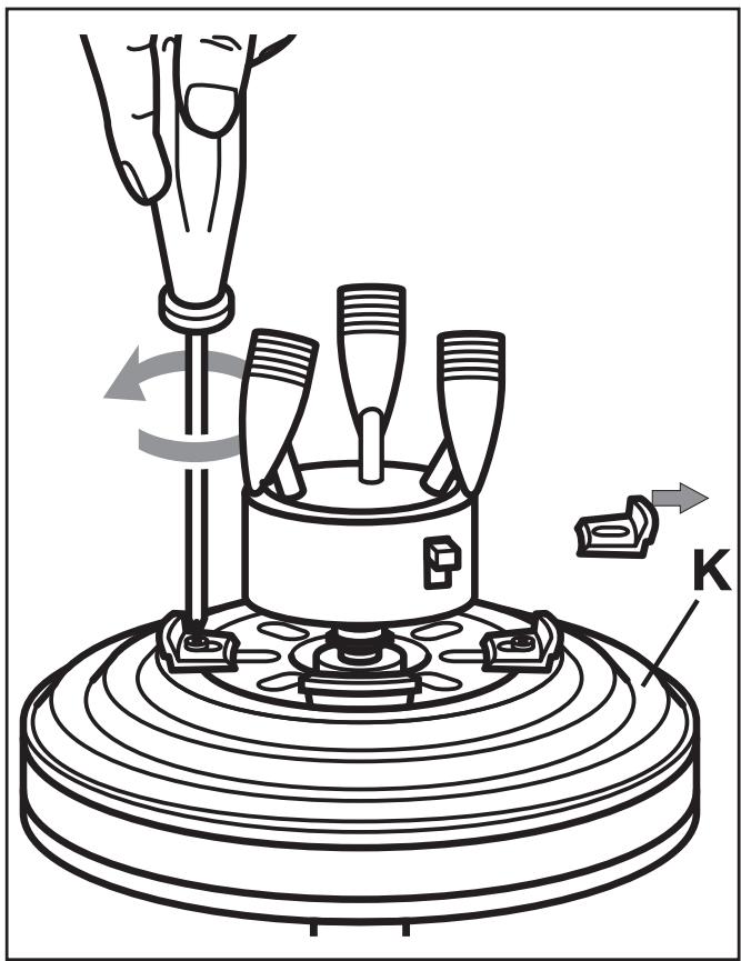
6.4 Removing the Transport Protection
1 Loosen the 3 transport securing screws on the motor housing (K).
2 Remove the screws with the lock washers as well as the transport protection elements.
3 Store the transport protection elements with the screws and lock washers for any future transports.
6.5 Installing the Blades (H)
1 Screw the blades firmly to the motor housing with 2 screws and washers each (see Fig.).
2 Slowly turn the fan for a few complete turns in order to check whether the blades are correctly installed. If the rotation is not smooth and easy, check the screw attachment of the blades.
6.6 Hanging the Fan
Danger:
You must make certain that the electrical connection wire is not under power.
Warning:
The room ceiling and the screw connection must be capable of bearing a weight of at least 28kg .
Use 8 × 50 ~mm screws with pegs.
For fastening to subceilings (e.g. Rigips), use special cavity pegs. Alternatively, you can determine whether the installation plate can be fastened to the lower structure of the subceiling (squared beam, girder) which is capable of bearing more weight, use wood screws.
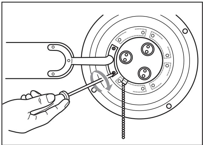
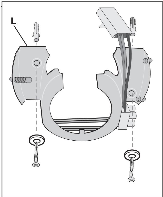
1 Fasten the installation plate (L) to the ceiling with 2 screws and, using the pegs if necessary.
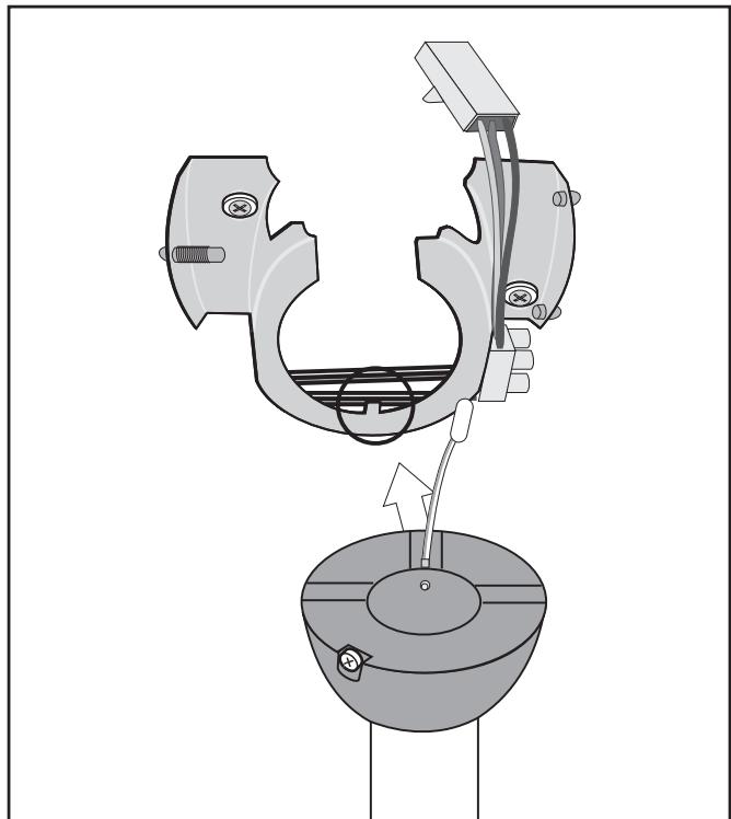
2 Hang the fan in the installation plate, making sure that the mount lines up properly with the notch (see Fig., circle).
3 Electrical connection.
DANGER:
The electrical connection may only be performed by a qualified electrician!
Failure to follow these instructions presents a life-threatening risk of electric shock!
Colour coding:
Green-yellow (I): PE conductor
Blue (II): Neutral conductor
Brown (III): Current-carrying wire (also: black)
Connect the electrical wires
Step 1: Connect the PE conductor to the lamp-wire connector (I).
Step 2: Connect the blue wire (N) (II).
Step 3: Connect the brown wire (L) (III).
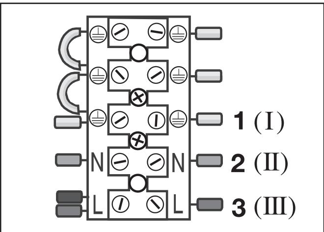
Connect the cable plug
Connect the cable plugs of the two PE conductors of the fan with the sockets on the installation plate.
Then connect the wide cable plug of the fan to the socket on the installation plate.
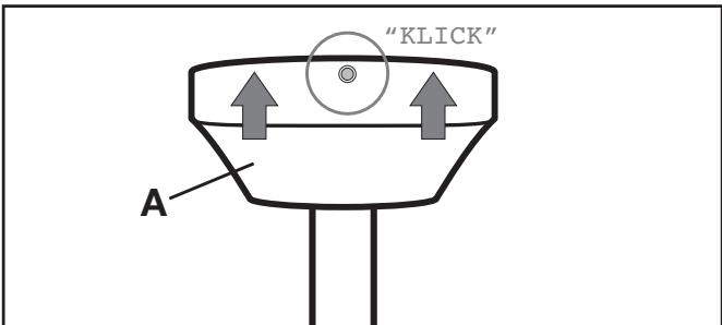
4 Snap the casing (A) onto the installation plate: insert it into the two adjacent bearings and snap it into the opposing spring-loaded bearing (click!).
① NOTE:
Avoid touching the halogen bulbs with your fingers. Use a clean cloth or cloth gloves when inserting the bulbs.
5 Insert the halogen bulbs into the lamp holders: Place the bulbs with light pressure into the round recesses and then turn them clockwise until securely fitted.
6 Switch on the power supply.
7.1 Setting the Speed
Adjust the speed level with the pull chain (G) on the motor housing. Each pull changes the speed in the following sequence:
Fast - medium - slow - OFF
Switch the lamps on and off with the middle pull chain (F).
If the fan is also to be switched on and off with a switch or a circuit breaker, it will start at the last speed set, unless it was switched off using the pull chain.
7.2 Setting the Direction
INFO: Direction
The fan turns counterclockwise:
Classic fan function. The downward air flow creates a cooling effect.
Typically used during warm times of the year.
The fan turns clockwise:
The air flow is directed toward the ceiling. The heated room air is distributed better throughout the room and the accumulation of warm air near the ceiling is prevented.
Caution:
To prevent damage to the fan motor, only operate the direction switch when the fan is stopped.
Change the direction with the sliding switch.
Switch positions:
Up: The fan turns clockwise.

Down: The fan turns counterclockwise. (as viewed from below)


Danger:
Disconnect the fan from the mains network before cleaning it: switch off the corresponding building fuse or circuit breaker. Touching cables or components under power presents a life-threatening risk!
Wipe the fan off with a soft cloth, which may be slightly moistened for stubborn dirt. Do not use any solvents, abrasive cleansers or sharp objects, e.g. rough sponges or brushes, to avoid scratching the fan.
9 Technical data
Product Ceiling Fan KH 1150
Mains voltage 220 - 240 V\~, 50 Hz
Rated power for fan 60 W
Lights 3× .50W GU10
Materials Metal and MDF
Dimensions 131 x 40 cm
(35 cm with the short extension rod)
Weight (incl.) 6,750 g
Labeled with
testingcertification CE,GS
10 Items supplied
1x Motor in the motor housing
1x Light module with bulb holders
5x Blades
5x Blade holders
1x Ceiling attachment with covering
1x Extension rod
3x Bulbs 50 W GU10
Plugs and screws
Assembly video (SVCD)
Operating instructions
| Problem/Fault | Possible Cause(s) | Remedy |
| The fastening screws cannot be screwed tightly or were turned too far during installation. | Replace the screws and nuts Only use screws that match the original screws; contact the manufacturer or retailer for information. | |
| The fan does not start. | Building fuse or circuit breaker defective. | Check the building fuse or circuit breaker and replace if necessary. |
| The direction switch is positioned in the middle. | Set the direction switch to the up or down position. | |
| Set the pull chain switch to the "OFF" setting. | Pull the pull chain once. | |
| Loose cable plug. | △ DANGER: Disconnect the fan from the mains network before checking the cable plug. Check the cable plug. | |
| Fan defective. | Have the ventilator checked by specialists or send it to Customer Services (Address - see Chapter "Warranty and Service"). | |
| Fan runs loudly or sways significantly. | Blade mounts not firmly connected. | Check the screw connection of the blade mounts. |
| Blade damaged. | Check the blades, replace if necessary. | |
| Blade not balanced out. | Change the positionings of the blades amongst themselves. | |
| Loosen blade attachment(s). | Check the blade attachments. | |
| Fan is not hung correctly. | △ DANGER: Disconnect the fan from the mains network before checking whether it is hung correctly. Check the fastening of the installation plate and extension rod, and correct any improper fastening. | |
| Light does not function. | Bulb defective. | Check the halogen bulbs and replace defective bulbs. |
| Loose cable plug. | △ DANGER: Disconnect the fan from the mains network before checking the cable plug. Check the cable plug. |
Do not perform any modifications or repairs on the product!
Safety-relevant parts may only be repaired by a specialist.
The warranty for this appliance is for 3 years from the date of purchase.
The appliance has been manufactured with care and meticulously examined before delivery. Please retain your receipt as proof of purchase. In the case of a warranty claim, please make contact by telephone with our service department. Only in this way can a post-free despatch for your goods be assured.
The warranty covers only claims for material and manufacturing defects, not for wearing parts or for damage to fragile components, e.g. buttons or batteries. The appliance is intended for domestic use only, NOT for commercial purposes.
If this product has been subjected to improper or inappropriate handling, abuse, or modifications not carried out by one of our authorised sales and service outlets, the warranty will be considered void. Your statutory rights are not restricted in any way by this warranty.
GB DES Ltd
Units 14-15
Bilston Industrial Estate
Oxford Street
Bilston
WV14 7EG
Tel.: 0870/787-6177
Fax: 0870/787-6168
e-mail: support.uk@kompernass.com
Irish Connection
Harbour view
Howth
Co. Dublin
Tel: 00353 (0) 87 99 62 077
Fax: 00353 18398056
e-mail: support.ie@kompernass.com
13 Importer
KOMPERNASS GMBH
BURGSTRASSE 21
D-44867 BOCHUM
www.kompernass.com
14 Disposal

Do not dispose of the appliance in your normal domestic waste. This appliance is subject to the European Guidelines 2002/96/EG.
Dispose of the appliance through an approved disposal centre or at your community waste facility.
Observe the currently applicable regulations.
In case of doubt, please contact your waste disposal centre.

Dispose of all packaging materials in an environmentally friendly manner.
6.2 Montering of forlaengerstang (B)
6.3 Montering of lysmodul (E)
FARE:
6.5 Montering of vinger (H)
Bna 2:Sigma oetov mAaywO (N) (II).
Bna 3:Sigma oetov kafo aywyo (L) (III).
