6704DW - Power Tools MAKITA - Free user manual and instructions
Find the device manual for free 6704DW MAKITA in PDF.

| Product Type | Cordless Angle Wrench |
| Brand | MAKITA |
| Model | 6704DW |
| Rated Voltage | 9.6 V DC |
| No-load Speed | 400 min⁻¹ |
| Tightening Torque | 2.0 - 7.8 N·m |
| Screw Capacity | Bolts/nuts/metal screws 4-6 mm; square 9.5 mm or 6.35 mm |
| Overall Length | 396 mm |
| Net Weight | 1.4 kg |
| Battery Type | Makita 9100 (Ni-Cd, 1.3 Ah, 8 cells) |
| Charging Time | Approximately 60 minutes |
| Charger | Included, compatible with Makita batteries |
| Torque Adjustment | Continuous, 5 positions (20 to 80 kg·cm) |
| Overload Protection | Automatic stop, restart after 20-30 seconds |
| Rotation Direction | Reversible (right/left) via reverser |
| Switch | Trigger with automatic return to OFF position |
| Safety Precaution | Do not touch metal parts in the presence of live cables |
| Maintenance | Clean with a dry cloth; repairs by a Makita authorized service center |
| Included Accessories | Battery, charger, rear cover, fixing screws, instruction manual |
Frequently Asked Questions - 6704DW MAKITA
User questions about 6704DW MAKITA
0 question about this device. Answer the ones you know or ask your own.
Ask a new question about this device
Download the instructions for your Power Tools in PDF format for free! Find your manual 6704DW - MAKITA and take your electronic device back in hand. On this page are published all the documents necessary for the use of your device. 6704DW by MAKITA.
USER MANUAL 6704DW MAKITA
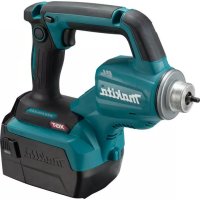
Cordless Angle Socket Driver
Instruction Manual
F
Explanation of general view
① Battery cartridge
② Set plate
③ Charging light
④ Battery charger
⑤ Hole for detent pin
⑥ Detent pin
⑦ Square drive
Bit with Form C 6.3 shank
⑨ Round drive
Switch trigger
(1) Reversing switch
12 Clockwise rotation
13 Counterclockwise rotation
14 Number
⑤ Adjusting ring
16 Red mark
17 Screw
SPECIFICATIONS
| Model | 6704D | 6706D |
| Capacities | ||
| Bolt, nut and machine screw | 4 mm – 6 mm | 4 mm – 6 mm |
| Square drive | 9.5 mm or 6.35 mm | 9.5 mm or 6.35 mm |
| No load speed (min-1) | 400 | 400 |
| Fastening torque | 2.0 N·m – 7.8 N·m | 2.0 N·m – 7.8 N·m |
| Overall length | 396 mm | 396 mm |
| Net weight | 1.4 kg | 1.4 kg |
| Rated voltage | D.C. 9.6 V | D.C. 9.6 V |
- Due to our continuing program of research and development, the specifications herein are subject to change without notice.
Note: Specifications may differ from country to country.
Safety hints
For your own safety, please refer to the enclosed safety instructions.
IMPORTANT SAFETY INSTRUCTIONS FOR CHARGER & BATTERY CARTRIDGE
- SAVE THESE INSTRUCTIONS - This manual contains important safety and operating instructions for battery charger.
- Before using battery charger, read all instructions and cautionary markings on (1) battery charger, (2) battery, and (3) product using battery.
- CAUTION - To reduce risk of injury, charge only MAKITA type rechargeable batteries. Other types of batteries may burst causing personal injury and damage.
- Do not expose charger to rain or snow.
- Use of an attachment not recommended or sold by the battery charger manufacturer may result in a risk of fire, electric shock, or injury to persons.
- To reduce risk of damage to electric plug and cord, pull by plug rather than cord when disconnecting charger.
- Make sure cord is located so that it will not be stepped on, tripped over, or otherwise subjected to damage or stress.
- Do not operate charger with damaged cord or plug — replace them immediately.
- Do not operate charger if it has received a sharp blow, been dropped, or otherwise damaged in any way; take it to a qualified serviceman.
- Do not disassemble charger or battery car
tridge; take it to a qualified serviceman when service or repair is required. Incorrect reassembly may result in a risk of electric shock or fire.
- To reduce risk of electric shock, unplug charger from outlet before attempting any maintenance or cleaning. Turning off controls will not reduce this risk.
ADDITIONAL SAFETY RULES FOR CHARGER & BATTERY CARTRIDGE
- Do not charge battery cartridge when temperature is BELOW 10^ (50^) or ABOVE 40^ (104^) .
- Do not attempt to use a step-up transformer, an engine generator or DC power receptacle.
- Do not allow anything to cover or clog the charger vents.
- Always cover the battery terminals with the battery cover when the battery cartridge is not used.
- Do not short the battery cartridge:
(1) Do not touch the terminals with any conductive material.
(2) Avoid storing battery cartridge in a container with other metal objects such as nails, coins, etc.
(3) Do not expose battery cartridge to water or rain.
A battery short can cause a large current flow, overheating, possible burns and even a breakdown.
- Do not store the machine and battery cartridge in locations where the temperature may reach or exceed 50^ (122^) .
-
Do not incinerate the battery cartridge even if it is severely damaged or is completely worn out. The battery cartridge can explode in a fire.
-
Be careful not to drop, shake or strike battery.
- Do not charge inside a box or container of any kind. The battery must be placed in a well ventilated area during charging.
ADDITIONAL SAFETY RULES FOR MACHINE
- Be aware that this machine is always in an operating condition, because it does not have to be plugged into an electrical outlet.
- Always be sure you have a firm footing. Be sure no one is below when using the machine in high locations.
- Hold the machine firmly.
- When driving into walls, floors or wherever "live" electrical wires may be encountered, DO NOT TOUCH ANY METAL PARTS OF THE MACHINE! Hold the machine only by the insulated grasping surfaces to prevent electric shock if you drive into a "live" wire.
- Check the socket carefully for wear, cracks or damage before installation.
SAVE THESE INSTRUCTIONS.
OPERATING INSTRUCTIONS
Installing or removing battery cartridge (Fig. 1)
Always switch off the machine before insertion or removal of the battery cartridge.
- To remove the battery cartridge, pull out the set plate on the machine and grasp both sides of the cartridge while withdrawing it from the machine.
- To insert the battery cartridge, align the tongue on the battery cartridge with the groove in the housing and slip it into place. Snap the set plate back into place. Be sure to close the set plate fully before using the machine.
- Do not use force when inserting the battery cartridge. If the cartridge does not slide in easily, it is not being inserted correctly.
Charging (Fig. 2)
- Plug the battery charger into your power source.
- Insert the battery cartridge so that the plus and minus terminals on the battery cartridge are on the same sides as their respective markings on the battery charger. Insert the cartridge fully into the port so that it rests on the charger port floor.
- When the battery cartridge is inserted, the charging light color will flash in red color and charging will begin.
-
When charging is completed, the charging light goes out. The charging time is as follows: Battery 9100 and 9100A: approx. 60 minutes.
-
If you leave the battery cartridge in the charger after the charging cycle is complete, the charger will switch into its "trickle charge (maintenance charge)" mode.
- After charging, remove the battery cartridge from the charger and unplug the charger from the power source.
| Battery type | Capacity (mAh) | Number of cells |
| 9100 | 1,300 | 8 |
CAUTION:
- The battery charger is for charging Makita battery cartridge. Never use it for other purposes or for other manufacturer's batteries.
- When you charge a new battery cartridge or a battery cartridge which has not been used for a long period of time, it may not accept a full charge. This is a normal condition and does not indicate a problem. You can recharge the battery cartridge fully after discharging it completely and recharging a couple of times.
- When you charge a battery cartridge from a just-operated machine or a battery cartridge which has been left in a location exposed to direct sunlight or heat for a long time, let it cool off. Then re-insert it and try to charge it once more.
- When you charge a new battery cartridge or a battery cartridge which has not been used for a long period, sometimes the charging light will go out soon. If this occurs, remove the battery cartridge and re-insert it. If the charging light goes out within one minute even after repeating this procedure a couple of times, the battery cartridge is dead. Replace it with a new one.
Trickle charge (Maintenance charge)
If you leave the battery cartridge in the charger to prevent spontaneous discharging after full charge, the charger will switch into its "trickle charge (maintenance charge)" mode and keep the battery cartridge fresh and fully charged.
Tips for maintaining maximum battery life
- Charge the battery cartridge before completely discharged.
Always stop machine operation and charge the battery cartridge when you notice less machine power.
- Never recharge a fully charged battery cartridge. Overcharging shortens the battery service life.
- Charge the battery cartridge with room temperature at 10^ - 40^ (50^ - 104^)
Let a hot battery cartridge cool down before charging it.
Installing or removing socket
Important:
Always be sure that the machine is switched off and the battery cartridge is removed before installing or removing the socket.
For machine with square drive (Fig. 3 & 4)
Use 9.5 mm square drive socket with a hole for detent pin which is available on the market. (Note: Use 6.35 mm square drive socket when using the machine with 6.35 mm square drive.)
To install the socket, depress the detent pin on the square drive with your finger and push the socket onto the square drive until the detent pin is inserted into the hole in the socket.
To remove the socket, depress the detent pin with a small hand tool and pull off the socket.
For machine with round drive (Fig. 5)
Use a bit with Form C 6.3 shank which is available on the market. The bit can be inserted directly into the round drive and held in place.
To install the bit, push it firmly into the round drive.
To remove the bit, grasp it with a pair of pliers and pull it out of the round drive. Sometimes, it helps to wiggle the bit with the pliers as you pull.
Switch action (Fig. 6)
CAUTION:
Before inserting the battery cartridge into the machine, always check to see that the switch trigger actuates properly and returns to the "OFF" position when released.
To start the machine, simply pull the trigger. Release the trigger to stop.
Reversing switch action (Fig. 6)
CAUTION:
Always check the direction of rotation before operation.
- Use the reversing switch only after the machine comes to a complete stop. Changing the direction of rotation before the machine stops may damage the machine.
This machine has a reversing switch to change the direction of rotation. Slide the reversing switch up for clockwise rotation or slide it down for counterclockwise rotation.
Overload protector
For 6704D and 6704DW
The overload protector automatically cuts out to break the circuit whenever heavy work is prolonged. Wait 20 - 30 seconds before resuming operation.
Adjusting the fastening torque (Fig. 7)
The fastening torque can be adjusted infinitely from approx. 20kg· cm to 80kg· cm . To adjust it, loosen the two screws and turn the adjusting ring. Then tighten the screws to secure the adjusting ring. Refer to the table below for relation between the numbers on the adjusting ring and the fastening torque to be obtained.
| Numbers on adjusting ring | Fastening torque to be obtained |
| 1 | 20 kg·cm |
| 2 | 35 kg·cm |
| 3 | 48 kg·cm |
| 4 | 60 kg·cm |
| 5 | 80 kg·cm |
(Example)
35 kg·cm of fastening torque can be obtained when the number 2 is aligned to the red mark.
NOTE:
- Always tighten the two screws to secure the adjusting ring after adjusting the fastening torque.
- The fastening torque may differ depending upon the kind of screws, the type of materials to be fastened, etc. Before starting your job, always perform a test operation to verify the adequate fastening torque.
Installing set plate (Fig. 8)
Always install the set plate when using battery cartridges 9100, 9102 or 9102A. Install the set plate on the machine with the screw provided as shown in Fig. 8.
Operation
The proper fastening torque may differ depending upon the kind or size of screws, the type of materials to be fastened, the condition of the threads, etc. Before starting your job, always perform a test operation to verify adequate fastening torque.
Hold the machine firmly with both hands whenever possible and place the socket over the bolt or nut. Then turn the machine on. As soon as the bolt or nut becomes tight, the clutch will cut in and the motor will stop automatically. Release the switch trigger.
When fastening machine screws, use the proper screwdriver bit shown in Fig. 9. It is commonly available on the market.
For 6706D and 6706DW
When the battery capacity decreases to a certain level, the motor will not start even if you press the switch trigger. This mechanism prevents poor fastening caused by battery voltage-drop. Charge the battery cartridge to resume operation.
NOTE:
Always use the correct size socket for bolts and nuts. An incorrect size socket will result in inaccurate and inconsistent fastening torque and/or damage to the bolt or nut.
- Hold the machine with its square drive pointed straight at the bolt or nut, or the bolt or nut will be damaged.
- If the motor will not start even after you pull the trigger, release the trigger. Then pull the trigger again after turning the socket slightly with your fingers.
MAINTENANCE
CAUTION:
Always be sure that the machine is switched off and the battery cartridge is removed before carrying out any work on the machine.
To maintain product safety and reliability, repairs, maintenance or adjustment should be carried out by a Makita Authorized Service Center.
GUARANTEE
We guarantee Makita machines in accordance with statutory/country-specific regulations. Damage attributable to normal wear and tear, overload or improper handling will be excluded from the guarantee. In case of complaint, please send the machine, undismantled, with the enclosed GUARANTEE CERTIFICATE, to your dealer or the Makita Service Center.
These accessories or attachments are recommended for use with your Makita machine specified in this manual. The use of any other accessories or attachments might present a risk of injury to persons. The accessories or attachments should be used only in the proper and intended manner.
F ACCESSIORES
ATTENTION :
EC-DECLARATION OF CONFORMITY
The undersigned, Yasuhiko Kanzaki, authorized
Makita Corporation, 3-11-8 Sumiyoshi-Cho, Anjo, Aichi, 446 Japan declares that this product
(Serlal No.: series production)
manufactured by Makita Corporation in Japan is in compliance with the following standards or standardized documents,
EN50260, EN55014
in accordance with Council Directives, 89/336/EEC and 98/37/EC.
ITALIANO
de accordo com as directivas 89/336/CEE e 98/37/CE do Conselho.
NORSK
EUs SAMSVARS-ERKLÄERING
EU-DEKLARATION OM KONFORMITET
Undertegnede, Yasuhiko Kanzaki, med fuldmagt fra Makita Corporation, 3-11-8 Sumiyoshi-Cho, Anjo, Aichi, 446 Japan, erklær hermed, at dette produkt (Læbenummer: sérieproduktion)
fremstilf at Makita Corporation i Japan, er i overensstemmelse med de falgende standarder aller normsattende dokumenter.
EN50260, EN55014
Michigan Drive, Tongwell, Milton Keynes,
Bucks MK15 8JD, U.K.
DC-1
ENGLISH
EC-DECLARATION OF CONFORMITY
The undersigned, Yasuhiko Kanzaki, authorized by Da Hong Transformer Factory, First building, First Row, Stock Investment Co. Factory Building First industry Zone, Ban Tian, Pu Ji Town, Long Gang Qu Shenzhen Guangdong, China declares that this product (Serial No.: series production) manufactured by Da Hong Transformer Factory in Chi is in compliance with the following standards or standardized documents.
EN60335, EN55014, EN61000* in accordance with Council Directives, 73/23/EEC and 89/336/EEC.
*from 1st Jan. 2001
FRANÇAISE
DECLARATION DE CONFORMITE CE
Je soussigné, Yasuhiko Kanzaki, mandate par Da Hong Transformer Factory, First building, First Row, Stock Investment Co. Factory Building First industry Zone, Ban Tian, Pu Ji Town, Long Gang Qu Shenzhen, Guangdong, China, déclare que ce produit
Michigan Drive, Tongwell, Milton Keynes, Bucks MK15 8JD, U.K.
PORTUGUES
DECLARACAO DE CONFORMIDADE DA CE
O abaixoassinado, Yasuhiko Kanzaki, autorizzato pada Da Hong Transformer Factory, First building, First Row, Stock Investment Co. Factory Building First industry Zone, Ban Tian, Pu Ji Town, Long Gang Qu Shenzhen, Guangdong, China, declara que este produits
EU-DEKLARATION OM KONFORMITET
Undertegnede, Yasuhiko Kanzaki, med fuldmagt fra Da Hong Transformer Factory, First building, First Row, Stock Investment Co. Factory Building First industry Zone, Ban Tian, Pu Ji Town, Long Gang Qu Shenzhen, Guangdong, China, erklarer hermed, at dette produit (Læbenummer: sérieproduktion) fremstillet af Da Hong Transformer Factory i China, er i overensstemmelse med de følgende standarder eller normalettende dokumente,
O unoypaphv, Yasuhiko Kanzaki, Eouaoodotnevooc ano tvn vtaipela Da Hong Transformer Factory, First building, First Row, Stock Investment Co. Factory Building First industry Zone, Ban Tian, Pu Ji Town, Long Gang Qu Shenzhen, Guangdong, China, nauvei 6n auto to npoiov
Michigan Drive, Tongwell, Milton Keynes,
Bucks MK15 8JD, U.K.
DC-2TC
ENGLISH
Noise And Vibration Of Model 6704D / 6705D / 6706D
The typical A-weighted sound pressure level is not more than 70 dB (A).
The noise level under working may exceed 85 dB (A).
- Wear ear protection. -
The typical weighted root mean square acceleration value is not more than 2.5m / s^2