5705RK - Circular saw MAKITA - Free user manual and instructions
Find the device manual for free 5705RK MAKITA in PDF.

| Product type | Circular saw |
| Brand | MAKITA |
| Model | 5705RK |
| Maximum blade diameter | 190 mm |
| Minimum blade diameter | 170 mm |
| Maximum cutting depth at 90° | 66 mm |
| Maximum cutting depth at 45° | 46 mm |
| No-load speed | 4 800 min⁻¹ |
| Total length | 356 mm |
| Net weight | 5,2 kg |
| Power supply | 220 - 250 V, single-phase, double insulation |
| Recommended supply impedance | ≤ 0,36 Ohms |
| Bevel cutting range | 0° to 45° |
| Compatible blade type | Circular steel blades, diameter 170-190 mm, thickness < 1,7 mm, kerf > 1,9 mm |
| Riving knife thickness | 1,8 mm |
| Sound pressure level | 98 dB(A) |
| Sound power level | 111 dB(A) |
| Weighted vibration acceleration | ≤ 2,5 m/s² |
| Main functions | Rip cuts, bevel cuts, depth adjustment, parallel guide, dust extraction connection, integrated riving knife |
| Maintenance | Brush replacement (wear up to mark), regular cleaning, periodic adjustments |
| Safety equipment | Lower guard with retraction handle, shaft lock, trigger release button, double insulation |
| Spare parts and repairability | Blades, brushes, flanges, bolt, hex wrench, riving knife. Repairs by authorized Makita center |
| Included accessories | Parallel guide, hex wrench, dust extraction adapter (optional?) |
Frequently Asked Questions - 5705RK MAKITA
User questions about 5705RK MAKITA
0 question about this device. Answer the ones you know or ask your own.
Ask a new question about this device
Download the instructions for your Circular saw in PDF format for free! Find your manual 5705RK - MAKITA and take your electronic device back in hand. On this page are published all the documents necessary for the use of your device. 5705RK by MAKITA.
USER MANUAL 5705RK MAKITA
The following show the symbols used for the tool. Be sure that you understand their meaning before use.
Symboles
Explanation of general view
① Hex wrench
② Shaft lock
③ Tighten
④ Loosen
⑤ Sawblade
⑥ Outer flange
⑦ Inner flange
Outer flange
⑨ Hex socket head bolt
10 Saw blade
① Setting protuberances
12 Hex socket head bolt (For adjusting riving knife)
⑬ Cutting depth
14 Loosen
15 Lever
16 Thumb nut
17 For 45^ bevel cuts
18 For straight cuts
19 Base plate
20 45^ angle cuts
21 Straight cuts
22 Top guide
23 Base
24 Lock-off button
Switch trigger
26 Vacuum cleaner
27 Limit mark
Brush holder cap
29 Screwdriven
SPECIFICATIONS
| Model | 5603R | 5705R | 5903R |
| Blade diameter | 165 mm | 190 mm | 235 mm |
| Max. cutting depth | |||
| At 90° | 54 mm | 66 mm | 85 mm |
| At 45° | 38 mm | 46 mm | 64 mm |
| No load speed (min-1) | 5,000 | 4,800 | 4,500 |
| Overall length | 330 mm | 356 mm | 400 mm |
| Net weight | 4.2 kg | 5.2 kg | 7.6 kg |
- Due to our continuing program of research and development, the specifications herein are subject to change without notice.
Note: Specifications may differ from country to country.
Power supply
The tool should be connected only to a power supply of the same voltage as indicated on the nameplate, and can only be operated on single-phase AC supply. They are double-insulated in accordance with European Standard and can, therefore, also be used from sockets without earth wire.
For model 5705R, public low-voltage distribution systems of between 220V and 250V
Switching operations of electric apparatus cause voltage fluctuations. The operation of this device under unfavorable mains conditions can have adverse effects to the operation of other equipment. With a mains impedance equal or less than 0.36 Ohms it can be presumed that there will be no negative effects.
The mains socket used for this device must be protected with a fuse or protective circuit breaker having slow tripping characteristics.
Safety hints
For your own safety, please refer to the enclosed Safety instructions.
ADDITIONAL SAFETY RULES FOR TOOL
ENB036-2
- Wear hearing protection.
- Keep Guards In Place and In Working Order. Never wedge or tie lower guard open. Check operation of lower guard before each use. Don't use if lower guard does not close briskly over saw blade.
CAUTION: If saw is dropped, lower guard may be bent, restricting full return.
- Do not use blades which are deformed or cracked.
- Do not use blades made of high speed steel.
- Do not stop the blades by lateral pressure on the saw blade.
- Keep Blades Clean and Sharp.
Sharp blades minimize stalling and kickback.
- DANGER: Keep Hands Away From Cutting Area. Keep hands away from blades. Don't reach underneath work while blade is rotating. Don't attempt to remove cut material when blade is moving.
CAUTION: Blades coast after turn off.
- Support Large Panels. (Fig. A & B)
Large panels must be supported as shown in Fig. A to minimize the risk of blade pinching and kickback.
When cutting operation requires the resting of the saw on the workpiece, the saw shall be rested on the larger portion and the smaller piece cut off.
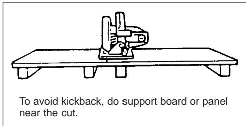
Fig. A
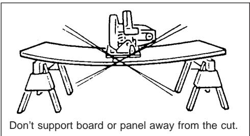
Fig.B
9. Use Rip Fence.
Always use a fence or straight edge guide when ripping.
10. Guard Against Kickback. (Fig. A & C)
Kickback occurs when the saw stalls rapidly and is driven back towards the operator. Release switch immediately if blade binds or saw stalls. Keep blades sharp. Support large panels as shown in Fig. A. Use fence or straight edge guide when ripping. Don't force tool. Stay alert-exercise control. Don't remove saw from work during a cut while the blade is moving.
NEVER place your hand or fingers behind the saw. If kickback occurs, the saw could easily jump backwards over your hand, possibly causing severe injury.
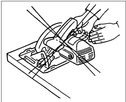
Fig. C
- Lower Guard. Raise lower guard with the retracting handle.
- Adjustments. Before cutting be sure depth and bevel adjustments are tight.
- Use Only Correct Blades In Mounting. Don't use blades with incorrect size holes. Never use defective or incorrect blade washers or bolts.
-
Avoid Cutting Nails. Inspect for and remove all nails from lumber before cutting.
-
When operating the saw, keep the cord away from the cutting area and position it so that it will not be caught on the workpiece during the cutting operation.
Operate with proper hand support, proper workpiece support, and supply cord routing away from the work area.
WARNING:
It is important to support the workpiece properly and to hold the saw firmly to prevent loss of control which could cause personal injury. Fig. D illustrates typical hand support of the saw.
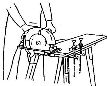
Fig. D
A typical illustration of proper hand support, workpiece support, and supply cord routing.
- Place the wider portion of the saw base on that part of the workpiece which is solidly supported, not on the section that will fall off when the cut is made.
As examples, Fig. E illustrates the RIGHT way to cut off the end of a board, and Fig. F the WRONG way. If the workpiece is short or small, clamp it down. DON'T TRY TO HOLD SHORT PIECES BY HAND! (Fig. F)
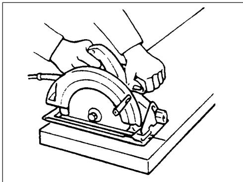
Fig. E
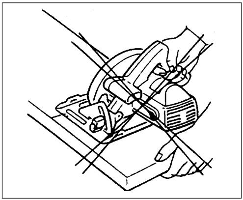
Fig. F 17.Never attempt to saw with the circular saw held upside down in a vise. This is extremely dangerous and can lead to serious accidents. (Fig.G)
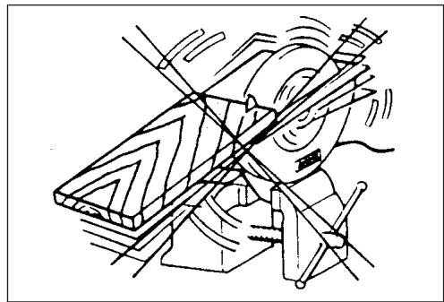
Fig. G
- Before setting the tool down after completing a cut, be sure that the lower (telescoping) guard has closed and the blade has come to a complete stop.
-
Using manufacturer data
-
Ensure that the diameter, thickness and other characteristics of the saw blade are suitable for the tool.
-
Ensure that the saw blade is suitable for the spindle speed of the tool.
-
Do not use any abrasive wheel.
SAVE THESE INSTRUCTIONS.
OPERATING INSTRUCTIONS
Removing or installing saw blade
The following blade can be used with this tool.
| Model | Max. dia. | Min. dia. | Blade thickness | Kerf |
| 5603R | 165 mm | 150 mm | less than 1.7 mm | more than 1.9 mm |
| 5705R | 190 mm | 170 mm | less than 1.7 mm | more than 1.9 mm |
| 5903R | 235 mm | 210 mm | less than 1.9 mm | more than 2.1 mm |
The thickness of the riving knife is 1.8mm for Models 5603R and 5705R or 2.0mm for Model for 5903R.
CAUTION:
- Do not use saw blades which do not comply with the characteristics specified in these instructions.
- Do not use saw blades the disc of which is thicker or the set of which is smaller than the thickness of the riving knife.
To remove the saw blade, depress the shaft lock fully to prevent shaft rotation, then use the hex wrench to loosen the hex socket head bolt. (Fig. 1)
Now remove the outer flange, raise the safety cover as much as possible, and remove the saw blade. (Fig. 2)
Install the saw blade using the reverse of the removal procedure. Install the inner flange, saw blade, outer flange and hex socket head bolt, in that order. Be sure to secure the hex socket head bolt tightly with the shaft lock fully depressed. (Fig. 1 & 3)
CAUTION:
- Make sure that the blade teeth point forward in the same direction as the tool rotation (the arrow on the blade should point in the same direction as the arrow on the tool).
- Never depress the shaft lock while the saw is running.
- Use only the Makita socket wrench to remove or install the blade.
Riving knife adjustment (Fig. 4)
Use the socket wrench to loosen the hex head socket bolt for the riving knife adjustment, then raise the safety cover. Move the riving knife up or down over the two protuberances for settings indicated in the illustration, so as to obtain the proper clearance between the riving knife and saw blade.
CAUTION:
Ensure that the riving knife is adjusted such that: The distance between the riving knife and the toothed rim of the saw blade is not more than 5mm The toothed rim does not extend more than 5mm beyond the lower edge of the riving knife.
Adjusting depth of cut (Fig. 5)
Loosen the lever on the depth guide and move the base up or down. At a desired depth of cut, secure the base by tightening the lever.
CAUTION:
- Use a shallow depth of cut when cutting thin workpiece for cleaner, safer cuts.
After adjusting the depth of cut, always tighten the lever securely.
Adjusting for bevel cuts (Fig. 6)
- Loosen the thumb nuts in front and back, and tilt the tool to the desired angle for bevel cuts (0 - 45^) . Secure the thumb nuts tightly in front and back after making the adjustment.
Sighting (5603R, 5705R) (Fig. 7)
For straight cuts, align the right notch on the front of the base with your cutting line on the workpiece. For 45^ bevel cuts, align the left notch with it.
Top guide (5903R) (Fig. 8)
Align your sight line with either the 0^ notch for straight cutting or the 45^ notch for 45^ angle cuts.
Switch action (Fig. 9)
CAUTION:
- Before plugging in the tool, always check to see that the switch trigger actuates properly and returns to the "OFF" position when released.
To prevent the switch trigger from being accidentally pulled, a lock-off button is provided. To start the tool, depress the lock-off button and pull the switch trigger. Release the switch trigger to stop.
Operation (Fig. 10)
Hold the tool firmly. Set the base plate on the workpiece to be cut without the blade making any contact. Then turn the tool on and wait until the blade attains full speed. Now simply move the tool forward over the workpiece surface, keeping it flat and advancing smoothly until the sawing is completed. To get clean cuts, keep your sawing line straight and your speed of advance uniform.
CAUTION:
- The riving knife should always be used except when plunging in the middle of the workpiece.
- Do not stop the saw blade by lateral pressure on the disc.
Guide rule (Fig. 11)
The handy guide rule allows you to do extra-accurate straight cuts. Simply slide the guide rule up snugly against the side of the workpiece and secure it in position with the screw on the front of the base. It also makes repeated cuts of uniform width possible.
Joint assembly (Fig. 12 & 13)
(for connecting a vacuum cleaner)
When you wish to perform clean cutting operation, connect a vacuum cleaner to your tool. Install the joint on the tool using the screw. Then connect a hose of vacuum cleaner to the joint.
MAINTENANCE
CAUTION:
Always be sure that the tool is switched off and unplugged before carrying out any work on the tool.
Replacement of carbon brushes (Fig. 14 & 15)
Replace carbon brushes when they are worn down to the limit mark. Both identical carbon brushes should be replaced at the same time.
To maintain product safety and reliability, repairs, maintenance or adjustment should be carried out by a Makita Authorized Service Center.
FRANÇAIS
Descriptif
Hiza alma (5603R, 5705R) (Sekil 7)
EC-DECLARATION OF CONFORMITY
The undersigned, Masahiro Yamaguchi, authorized by Makita Manufacturing Europe Ltd., Road 7, Hortonwood Industrial Estate, Telford, Shropshire TF1 4GP, United Kingdom declares that this product
(Serial No.: series production)
manufactured by Makita Manufacturing Europe Ltd. is in compliance with the following standards or standardized documents,
HD400, EN50144, EN55014-1, EN55014-2,
EN61000-3-2, EN61000-3-3
in accordance with Council Directives, 73/23/EEC, 89/336/EEC and 98/37/EC.
FRANÇAISE
DECLARATION DE CONFORMITE CE
de accordo com as directivas 73/23/CEE, 89/336/CEE e 98/37/CE do Conselho.
DANSK
EU-DEKLARATION OM KONFORMITET
Undertegnede, Masahiro Yamaguchi, med fuldmagt fra Makita Manufacturing Europe Ltd., Road 7, Hortonwood Industrial Estate, Telford, Shropshire TF1 4GP, United Kingdom, erkræer hermed, at dette produit
The typical A-weighted noise levels are
sound pressure level: 96 dB (A)
sound power level: 109 dB (A)
- Wear ear protection. -
The typical weighted root mean square acceleration value is not more than 2.5m / s^2
FRANCAISE
aänenpainetaso: 96 dB (A)
The typical A-weighted noise levels are
sound pressure level: 98 dB (A)
sound power level: 111 dB (A)
- Wear ear protection. -
The typical weighted root mean square acceleration value is not more than 2.5m / s^2
FRANÇAISE
The typical A-weighted noise levels are
sound pressure level: 95 dB (A)
sound power level: 108 dB (A)
- Wear ear protection. -
The typical weighted root mean square acceleration value is not more than 2.5m / s^2