B75MA-P45 - Motherboard MSI - Free user manual and instructions
Find the device manual for free B75MA-P45 MSI in PDF.

User questions about B75MA-P45 MSI
0 question about this device. Answer the ones you know or ask your own.
Ask a new question about this device
Download the instructions for your Motherboard in PDF format for free! Find your manual B75MA-P45 - MSI and take your electronic device back in hand. On this page are published all the documents necessary for the use of your device. B75MA-P45 by MSI.
USER MANUAL B75MA-P45 MSI
The material in this document is the intellectual property of MICRO-STAR INTERNATIONAL. We take every care in the preparation of this document, but no guarantee is given as to the correctness of its contents. Our products are under continual improvement and we reserve the right to make changes without notice.
Trademarks
All trademarks in this manual are properties of their respective owners.
MSI® is registered trademark of Micro-Star Int'l Co., Ltd.
NVIDIA® is registered trademark of NVIDIA Corporation.
ATI® is registered trademark of AMD Corporation.
AMD® is registered trademarks of AMD Corporation.
Intel® is registered trademarks of Intel Corporation.
Windows® is registered trademarks of Microsoft Corporation.
AMI is registered trademark of American Megatrends Inc.
Award® is a registered trademark of Phoenix Technologies Ltd.
Sound Blaster® is registered trademark of Creative Technology Ltd.
Realtek® is registered trademark of Realtek Semiconductor Corporation.
- JMicron® is registered trademark of JMicron Technology Corporation.
Netware® is registered trademark of Novell, Inc.
Lucid® is trademark of LucidLogix Technologies, Ltd.
VIA® is registered trademark of VIA Technologies, Inc.
■ ASMedia® is registered trademark of ASMedia Technology Inc.
iPad, iPhone, and iPod are trademarks of Apple Inc.
Revision History
| Revision | Revision History | Date |
| V3.0 | First release for PCB 3.X (Europe version) | 2012/ 06 |
Technical Support
If a problem arises with your system and no solution can be obtained from the user's manual, please contact your place of purchase or local distributor. Alternatively, please try the following help resources for further guidance.

Visit the MSI website for technical guide, BIOS updates, driver updates, and other information:
http://www.msi.com/service/download

Contact our technical staff at:
http://support.msi.com
Safety Instructions
Always read the safety instructions carefully.
- Keep this User's Manual for future reference.
- Keep this equipment away from humidity.
Lay this equipment on a reliable flat surface before setting it up.
- The openings on the enclosure are for air convection hence protects the equipment from overheating. DO NOT COVER THE OPENINGS.
Make sure the voltage of the power source is at 110/220V before connecting the equipment to the power inlet.
- Place the power cord such a way that people can not step on it. Do not place anything over the power cord.
Always Unplug the Power Cord before inserting any add-on card or module.
All cautions and warnings on the equipment should be noted.
- Never pour any liquid into the opening that can cause damage or cause electrical shock.
If any of the following situations arises, get the equipment checked by service personnel:
The power cord or plug is damaged.
Liquid has penetrated into the equipment.
The equipment has been exposed to moisture.
The equipment does not work well or you can not get it work according to User's Manual.
The equipment has been dropped and damaged.
The equipment has obvious sign of breakage.
DO NOT LEAVE THIS EQUIPMENT IN AN ENVIRONMENT ABOVE 60^ (140^) IT MAY DAMAGE THE EQUIPMENT.
FCC-B Radio Frequency Interference Statement
This equipment has been tested and found to comply with the limits for a Class B digital device, pursuant to Part 15 of the FCC Rules. These limits are designed to provide reasonable protection against harmful inter

ference in a residential installation. This equipment generates, uses and can radiate radio frequency energy and, if not installed and used in accordance with the instructions, may cause harmful interference to radio communications. However, there is no guarantee that interference will not occur in a particular installation. If this equipment does cause harmful interference to radio or television reception, which can be determined by turning the equipment off and on, the user is encouraged to try to correct the interference by one or more of the measures listed below.
Reorient or relocate the receiving antenna.
- Increase the separation between the equipment and receiver.
- Connect the equipment into an outlet on a circuit different from that to which the receiver is connected.
Consult the dealer or an experienced radio/television technician for help.
Notice 1
The changes or modifications not expressly approved by the party responsible for compliance could void the user's authority to operate the equipment.
Notice 2
Shielded interface cables and A.C. power cord, if any, must be used in order to comply with the emission limits.
VOIR LA NOTICE D'INSTALLATION AVANT DE RACCORDER AU RESEAU.

Micro-Star International
MS-7758
This device complies with Part 15 of the FCC Rules. Operation is subject to the following two conditions:
1) this device may not cause harmful interference, and
2) this device must accept any interference received, including interference that may cause undesired operation.
Battery Information

European Union:
Batteries, battery packs, and accumulators should not be disposed of as unsorted household waste. Please use the public collection system to return, recycle, or treat them in compliance with the local regulations.

Taiwan:
For better environmental protection, waste batteries should be collected separately for recycling or special disposal.
廢電池請回收
California, USA:
The button cell battery may contain perchlorate material and requires special handling when recycled or disposed of in California.
For further information please visit:
http://www.dtsc.ca.gov/hazardouswaste/perchlorate/
CAUTION: There is a risk of explosion, if battery is incorrectly replaced.
Replace only with the same or equivalent type recommended by the manufacturer.
Chemical Substances Information
In compliance with chemical substances regulations, such as the EU REACH Regulation (Regulation EC No. 1907/2006 of the European Parliament and the Council), MSI provides the information of chemical substances in products at:
http://www.msi.com/html/popup/csr/evmptrtt_pcm.html
BSMI EMI 聲明
警告使用者:
WEEE (Waste Electrical and Electronic Equipment) Statement
ENGLISH
To protect the global environment and as an environmentalist, MSI must remind you that...
Under the European Union ("EU") Directive on Waste Electrical and Electronic Equipment, Directive 2002/96/EC, which takes effect on August 13, 2005, products of "electrical and electronic equipment" cannot be discarded as municipal wastes anymore, and manufacturers of covered electronic equipment
will be obligated to take back such products at the end of their useful life. MSI will comply with the product take back requirements at the end of life of MSI-branded products that are sold into the EU. You can return these products to local collection points.

DEUTSCH
Mainboard Specifications
Processor Support
Support 3rd Gen Intel® Core™ i7/ Core™ i5/ Core™ i3/ Pentium®/ Celeron® Processors for LGA 1155 socket
Chipset
Intel® Z77 chipset (Z77A-G41)
Intel® H77 chipset (ZH77A-G41)
Intel® B75 chipset (B75A-G41)
- Supports Intel® SBA by Intel® B75
Memory Support
4x DDR3 DIMMs support up to 32GB
- Support for DDR3-1066/ 1333/ 1600/ 1866(OC)/ 2133(OC), 2200^ / 2400^ / 2667^ / 2800^ MHz (OC, 22nm CPU required) (Z77A-G41)
- Support for DDR3-1066/ 1333/ 1600/ 1800/ 2000/ 2200/ 2400 MHz (OC, 22nm CPU required) (ZH77A-G41, B75A-G41)
Supports Dual-Channel mode
LAN
Supports LAN 10/100/1000 Fast Ethernet by Realtek® RTL8111E
Audio
Integrated HD audio codec by Realtek® ALC887
8-channel audio with jack sensing
Compliant with Azalia 1.0 Spec
SATA
SATA 6Gb/s
- 2x SATA 6Gb/s ports (SATA1~2) by Intel® Z77/ H77 (Z77A-G41/ ZH77A-G41)
- 1x SATA 6Gb/s port (SATA1) by Intel® B75 (B75A-G41)
SATA 3Gb/s
- 4x SATA 3Gb/s ports (SATA3~6) by Intel® Z77/ H77 (Z77A-G41/ ZH77A-G41)
- 5x SATA 3Gb/s ports (SATA2~6) by Intel® B75 (B75A-G41)
RAID (Z77A-G41/ ZH77A-G41)
SATA1~6 support Intel® Rapid Storage Technology (AHCI/ RAID 0/1/5/10)
USB 3.0
2x USB 3.0 rear IO ports by Intel® Z77/H77/B75
- 1x USB 3.0 onboard connector by Intel® Z77/H77/B75
Multi-GPU
Supports AMD® CrossFire™ Technology
Connectors
Back panel
- 1x PS/2 mouse port
-
1x PS/2 keyboard port
-
4x USB 2.0 ports
- 2x USB 3.0 ports
- 1x LAN port
- 1x HDMI port** , supports a maximum resolution of 1920x1200 @ 60 Hz
- 1x VGA port**, supports a maximum resolution of 2048x1536 @ 75 Hz
- 3x audio ports***
(**This mainboard supports dual-display function by two onboard graphics output ports).
(***To reach the 8-channel sound effect, the 7th and 8th channels must be outputted from front panel.)
On-Board
- 2x USB 2.0 connectors
- 1x USB 3.0 connector
- 1x TPM Module connector
- 1x Serial Port connector
- 1x Parallel Port connector
- 1x Front Panel Audio connector
- 1x Chassis Intrusion connector
- 1x MultiConnect Panel connector (optinoal)
- 1x Voice Genie connector (optional)
Slots
- 1x PCIe 3.0 x16 slot, PCI_E2, it supports up to PCIe 3.0 x16 speed
1x PCIe 2.0 x16 slot, PCI_E4, it supports up to PCIe 2.0 x4 speed
2x PCIe 2.0 x1 slots
2xPCI slots
Form Factor
ATX (30.5 cm × 21.6 cm)
Mounting Screw Holes
6x mounting holes

For the latest information about CPU, please visit http://www.msi.com/service/cpu-support

For more information on compatible components, please visit http://www.msi.com/service/test-report
If you need to purchase accessories and request the part numbers, you could search the product web page and find details on our web address http://www.msi.com/index.php
Connectors Quick Guide
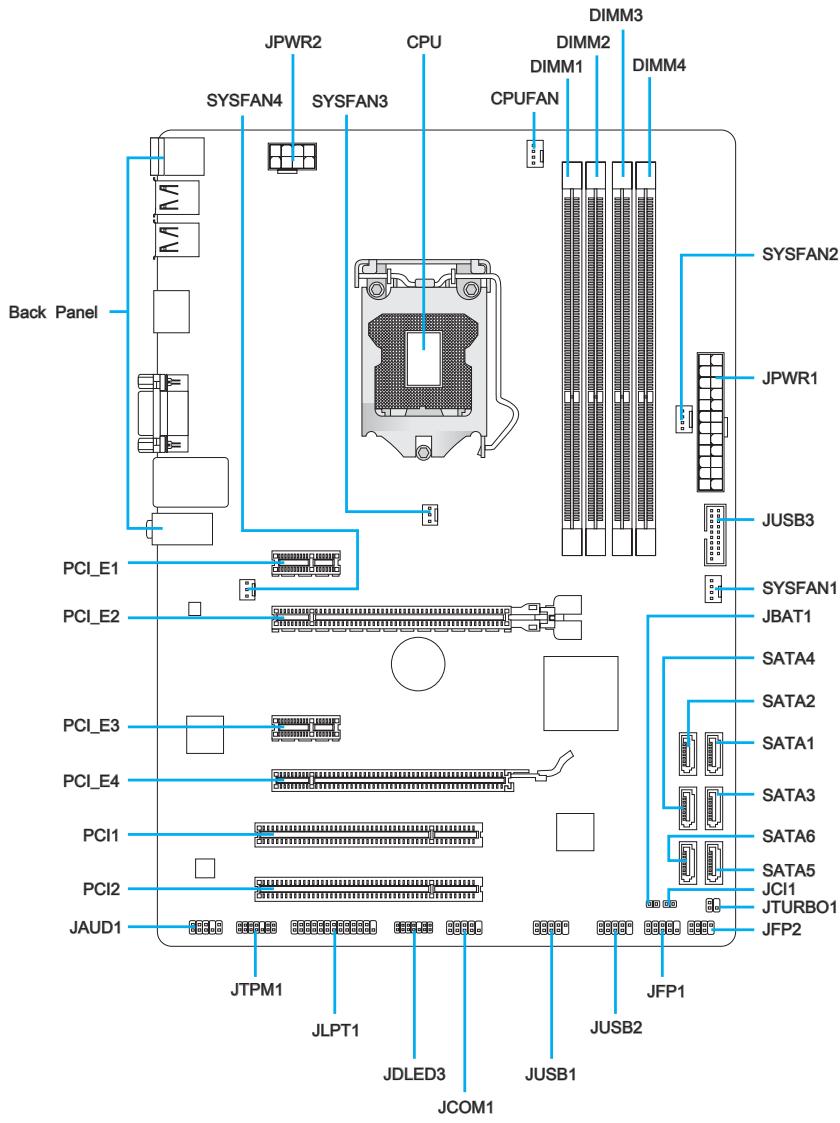
Connectors Reference Guide
| Port Name | Port Type | Page |
| Back Panel | I/O Ports | En-6 |
| CPU | LGA 1155 CPU Socket | En-9 |
| CPUFAN,SYSFAN1~4 | Fan Power Connectors | En-19 |
| DIMM1~4 | DDR3 Memory Slots | En-14 |
| JAUD1 | Front Panel Audio Connector | En-23 |
| JBAT1 | Clear CMOS Jumper | En-26 |
| JCI1 | Chassis Intrusion Connector | En-22 |
| JCOM1 | Serial Port Connector | En-24 |
| JDLED3 | Voice Genie Connector | En-25 |
| JFP1, JFP2 | Front Panel Connectors | En-20 |
| JLPT1 | Parallel Port Connector | En-24 |
| JPWR1 | ATX 24-pin Power Connector | En-13 |
| JPWR2 | ATX 8-pin Power Connector | En-13 |
| JTPM1 | TPM Module Connector | En-23 |
| JTURBO1 | MultiConnect Panel Connector | En-25 |
| JUSB1~2 | USB 2.0 Expansion Connectors | En-22 |
| JUSB3 | USB 3.0 Expansion Connector | En-21 |
| PCI1~2 | PCI Expansion Slots | En-17 |
| PCI_E2, PCI_E4 | PCIe x16 Expansion Slots | En-16 |
| PCI_E1, PCI_E3 | PCIe x1 Expansion Slots | En-16 |
| SATA1 | SATA 6Gb/s Connector | En-18 |
| SATA2 | SATA 6Gb/s or 3Gb/s Connector | En-18 |
| SATA3~6 | SATA 3Gb/s Connectors | En-18 |
Back Panel Quick Guide
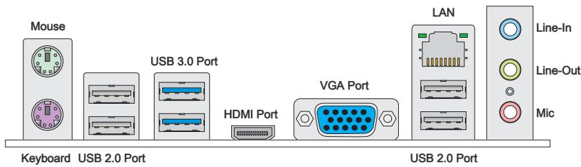
Mouse/Keyboard
The standard PS/2® mouse/ keyboard DIN connector for a PS/2® mouse/ keyboard.
USB 2.0 Port
The USB 2.0 port is for attaching USB 2.0 devices such as keyboard, mouse, or other USB 2.0-compatible devices.
USB 3.0 Port
USB 3.0 port is backward-compatible with USB 2.0 devices. It supports data transfer rate up to 5 Gbit/s (SuperSpeed).

Important
In order to use USB 3.0 devices, you must connect to a USB 3.0 port. If a USB cable is used, it must be USB 3.0 compliant.
> HDMI Port

The High-Definition Multimedia Interface (HDMI) is an all-digital audio-video interface that is capable of transmitting uncompressed streams. HDMI supports all types of TV formats, including standard, enhanced, or high-definition video, plus multi-channel digital audio on a single cable.
VGA Port
The DB15-pin female connector is provided for monitor.

Important
This mainboard supports dual-display function by two onboard graphics output ports.
LAN
The standard RJ-45 LAN jack is for connecting to a Local Area Network (LAN).

| LED | Color | LED State | Condition |
| Left | Yellow | Off | LAN link is not established. |
| On(Steady) | LAN link is established. | ||
| On(FLASHING) | The computer is communicating with another computer on the network. | ||
| Right | Green | Off | 10 Mbits/sec data rate |
| On | 100 Mbits/sec data rate | ||
| Orange | On | 1000 Mbits/sec data rate |
Audio Ports
These connectors are used for audio devices. The color of the jack refers to the function of the connector.
Blue-Line in: Used for connecting external audio outputting devices.
- Green-Line out: Used as a connector for speakers or headphone.
Pink-Mic:Used as a connector for a microphone.

Important
To reach the 8-channel sound effect, the 7th and 8th channels must be outputted from front panel.
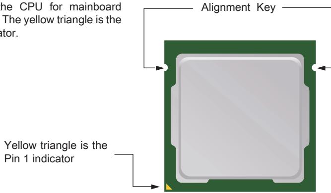
CPU (Central Processing Unit)
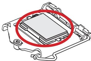
Introduction to the LGA 1155 CPU
The surface of the LGA 1155 CPU has two alignment keys and a yellow triangle to assist in correctly lining up the CPU for mainboard placement. The yellow triangle is the Pin 1 indicator.

Important
Overheating
Overheating can seriously damage the CPU and mainboard. Always make sure the cooling fans work properly to protect the CPU from overheating. Be sure to apply an even layer of thermal paste (or thermal tape) between the CPU and the heatsink to enhance heat dissipation.
Replacing the CPU
When replacing the CPU, always turn off the system's power supply and unplug the power supply's power cord to ensure the safety of the CPU.
Overclocking
This mainboard is designed to support overclocking. Before attempting to overclock, please make sure that all other system components can tolerate overclocking. Any attempt to operate beyond product specifications is not recommend. MSI does not guarantee the damages or risks caused by inadequate operation beyond product specifications.
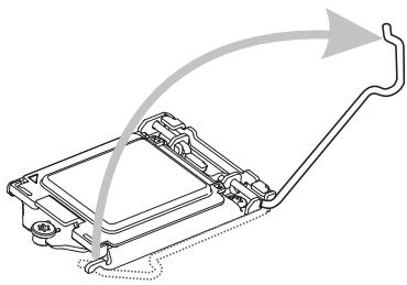
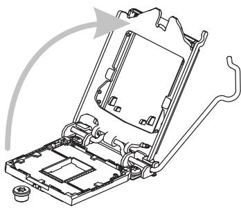
CPU & Cooler Installation
When installing a CPU, always remember to install a CPU cooler. A CPU cooler is necessary to prevent overheating and maintain system stability. Follow the steps below to ensure correct CPU and CPU cooler installation. Wrong installation can damage both the CPU and the mainboard.
- Unhook and lift the loading lever to the fully open position.
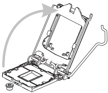
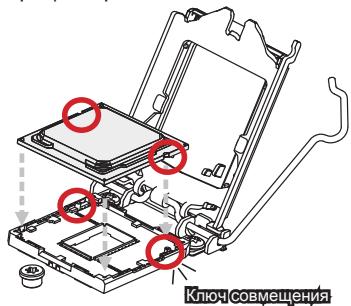
- Line up the CPU to fit the CPU socket. Be sure to hold the CPU by the base with the metal contacts facing downward. The alignment keys on the CPU will line up with the edges of the CPU socket to ensure a correct fit.

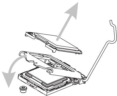
- The loading plates should automatically lift up as the loading lever is pushed to the fully open position. Do not touch any of the CPU socket pins.
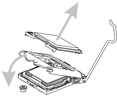
- Close the loading plate and remove the plastic protective cap.
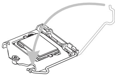
- Inspect the CPU to check if it is properly seated in the socket. Press the loading lever down and lock it under the retention tab.
- Locate the CPU fan connector on the mainboard.
- Evenly spread a thin layer of thermal paste (or thermal tape) on the top of the CPU. This will help in heat dissipation and prevent CPU overheating.
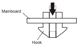
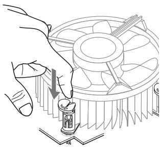
- Place the heatsink on the mainboard with the fan's wires facing towards the fan connector and the hooks matching the holes on the mainboard.
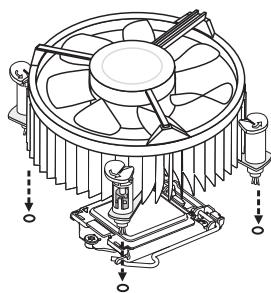
- Push down on the heatsink until the four clips get wedged into the holes on the mainboard. Press the four hooks down to fasten the cooler. As each hook locks into position a click should be heard.
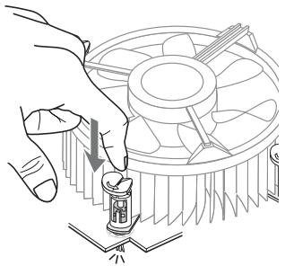
- Inspect the mainboard to ensure that the clip-ends have been properly locked in place.
- Finally, attach the CPU fan cable to the CPU fan connector on the mainboard.

Important
- Do not touch the CPU socket pins.
- Confirm that the CPU cooler has formed a tight seal with the CPU before booting your system.
- Whenever the CPU is not installed, always protect the CPU socket pins by covering the socket with the plastic cap.
- Please refer to the documentation in the CPU cooler package for more details about CPU cooler installation.
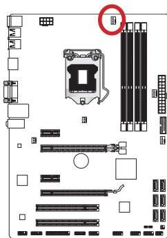
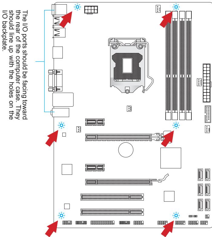
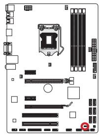
Mounting Screw Holes
When installing the mainboard, first install the necessary mounting stands required for a mainboard on the mounting plate in your computer case. If there is an I/O back plate that came with the computer case, please replace it with the I/O backplate that came with the mainboard package. The I/O backplate should snap easily into the computer case without the need for any screws. Align the mounting plate's mounting stands with the screw holes on the mainboard and secure the mainboard with the screws provided with your computer case. The locations of the screw holes on the mainboard are shown below. For more information, please refer to the manual that came with the computer case.

Important
- Install the mainboard on a flat surface free from unnecessary debris.
- To prevent damage to the mainboard, any contact between the mainboard circuitry and the computer case, except for the mounting stands, is prohibited.
- Please make sure there are no loose metal components on the mainboard or within the computer case that may cause a short circuit of the mainboard.
Power Supply
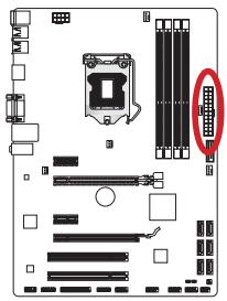
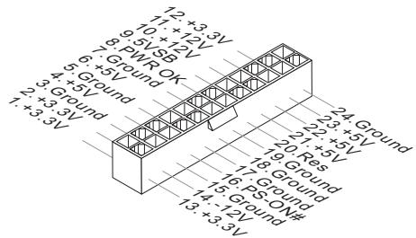
JPWR1:ATX24-pinPowerConnector
This connector allows you to connect an ATX 24-pin power supply. To connect the ATX 24-pin power supply, align the power supply cable with the connector and firmly press the cable into the connector. If done correctly, the clip on the power cable should be hooked on the mainboard's power connector.
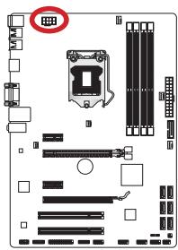
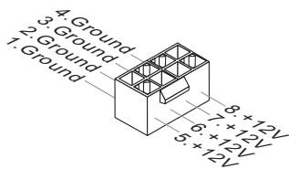
JPWR2:ATX 8-pin Power Connector
This connector provides 12V power to the CPU.

Important
Make sure that all the power cables are securely connected to a proper ATX power supply to ensure stable operation of the mainboard.
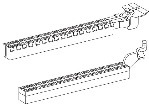
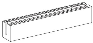
Memory
These DIMM slots are used for installing memory modules. For more information on compatible components, please visit http://www.msi.com/service/test-report
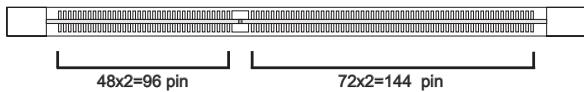
DDR3
240-pin, 1.5V
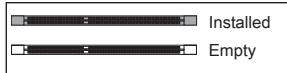
Dual-Channel mode Population Rule
In Dual-Channel mode, the memory modules can transmit and receive data with two data bus channels simultaneously. Enabling Dual-Channel mode can enhance system performance. The following illustrations explain the population rules for Dual-Channel mode.
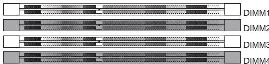
1
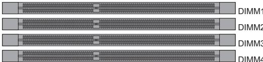
2

Important
- DDR3 memory modules are not interchangeable with DDR2, and the DDR3 standard is not backward compatible. Always install DDR3 memory modules in DDR3 DIMM slots.
- To ensure system stability, memory modules must be of the same type and density in Dual-Channel mode.
- Due to chipset resource usage, the system will only detect up to 31+ GB of memory (not full 32 GB) when all DIMM slots have 8GB memory modules installed.
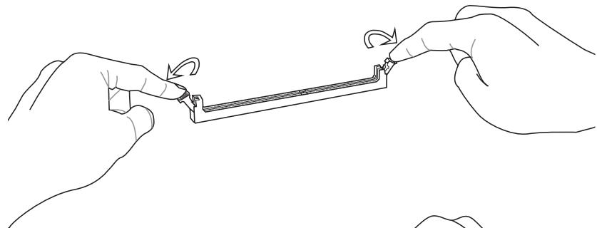
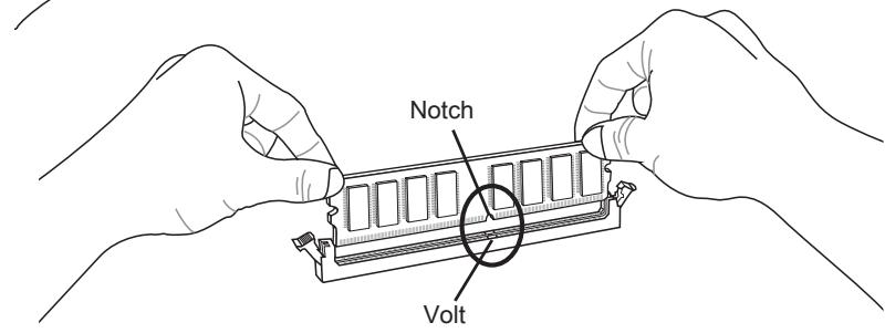
Installing Memory Modules
- Unlock the DIMM slot by pushing the mounting clips to the side. Vertically insert the memory module into the DIMM slot. The memory module has an off-center notch on the bottom that will only allow it to fit one way into the DIMM slot.
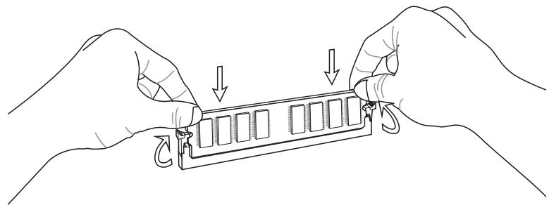
- Push the memory module deep into the DIMM slot. The plastic clips at each side of the DIMM slot will automatically close when the memory module is properly seat and an audible click should be heard.
- Manually check if the memory module has been locked in place by the DIMM slot's side clips.
Expansion Slots
This mainboard contains numerous ports for expansion cards, such as discrete graphics or audio cards.
PCIe (Peripheral Component Interconnect Express) Slot
The PCIe slot supports the PCIe interface expansion card.
PCIe 3.0 x16 Slot
PCIe 2.0 x16 Slot
PCIe 2.0 x1 Slot
PCI (Peripheral Component Interconnect) Slot
The PCI slot supports additional LAN, SCSI, USB, and other add-on cards that comply with PCI specifications.

32-bit PCI Slot

Important
When adding or removing expansion cards, always turn off the power supply and unplug the power supply power cable from the power outlet. Read the expansion card's documentation to check for any necessary additional hardware or software changes.
PCI Interrupt Request Routing
IRQ, or interrupt request lines, are hardware lines over which devices can send interrupt requests to the processor. The PCI IRQ pins are typically connected to the PCI bus pins as followed:
| Order1 | Order2 | Order3 | Order4 | |
| PCI Slot1 | INT A# | INT B# | INT C# | INT D# |
| PCI Slot2 | INT B# | INT C# | INT D# | INT A# |
Internal Connectors
SATA1~6: SATA Connector
This connector is a high-speed SATA interface port. Each connector can connect to one SATA device. SATA devices include disk drives (HDD), solid state drives (SSD), and optical drives (CD/DVD/Blu-Ray).
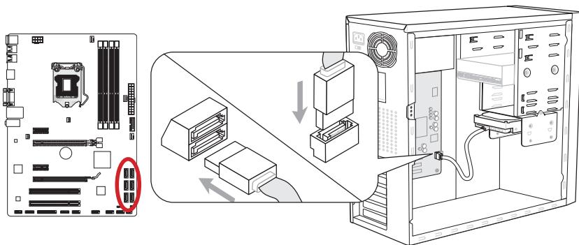
* The MB layout in this figure is for reference only.
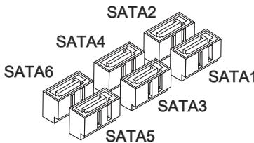
SATA1 (6Gb/s, by Intel® Z77/H77/B75)
SATA2 (6Gb/s, by Intel® Z77/H77)
(3Gb/s, by Intel® B75)
SATA3~6 (3Gb/s, by Intel® Z77/ H77/ B75)

Important
- Many SATA devices also need a power cable from the power supply. Such devices include disk drives (HDD), solid state drives (SSD), and optical drives (CD / DVD / Blu-Ray). Please refer to the device's manual for further information.
- Many computer cases also require that large SATA devices, such as HDDs, SSDs, and optical drives, be screwed down into the case. Refer to the manual that came with your computer case or your SATA device for further installation instructions.
- Please do not fold the SATA cable at a 90-degree angle. Data loss may result during transmission otherwise.
- SATA cables have identical plugs on either sides of the cable. However, it is recommended that the flat connector be connected to the mainboard for space saving purposes.
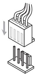
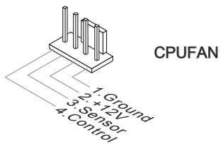
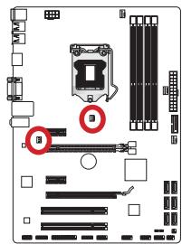
CPUFAN,SYSFAN1~4: Fan Power Connectors
The fan power connectors support system cooling fans with +12V . If the mainboard has a System Hardware Monitor chipset on-board, you must use a specially designed fan with a speed sensor to take advantage of the CPU fan control. Remember to connect all system fans. Some system fans may not connect to the mainboard and will instead connect to the power supply directly. A system fan can be plugged into any available system fan connector.
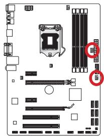
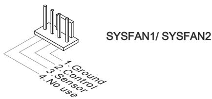
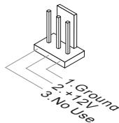
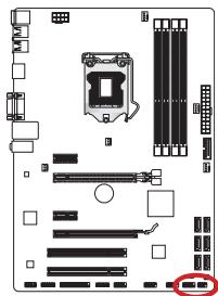
SYSFAN3/ SYSFAN4

Important
- Please refer to your processor's official website or consult your vendor to find recommended CPU cooling fans.
- The CPUFAN connector supports Smart Fan Control with linear mode. The Control Center II utility can be installed to automatically control the fan speeds according to the CPU's temperature.
- If there are not enough ports on the mainboard to connect all system fans, adapters are available to connect a fan directly to a power supply.
- Before first boot up, ensure that there are no cables impeding any fan blades.
JFP1, JFP2: Front Panel Connectors
These connectors connect to the front panel switches and LEDs. The JFP1 connector is compliant with the Intel® Front Panel I/O Connectivity Design Guide. When installing the front panel connectors, please use the enclosed mConnectors to simplify installation. Plug all the wires from the computer case into the mConnectors and then plug the mConnectors into the mainboard.
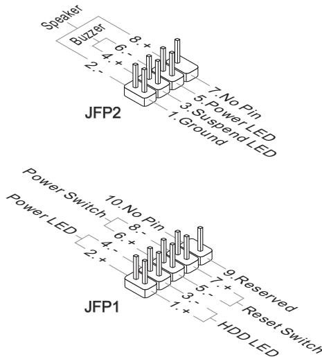

Important
- On the connectors coming from the case, pins marked by small triangles are positive wires. Please use the diagrams above and the writing on the mConnectors to determine correct connector orientation and placement.
- The majority of the computer case's front panel connectors will primarily be plugged into JFP1.
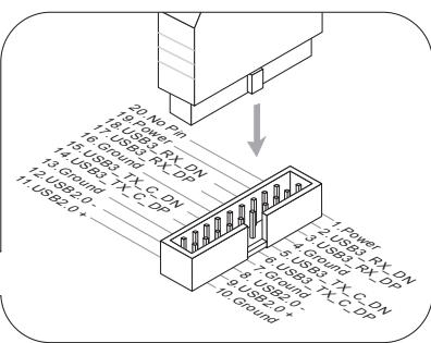
JUSB3: USB 3.0 Expansion Connector
The USB 3.0 port is backwards compatible with USB 2.0 devices. It supports data transfer rates up to 5Gbits/s (SuperSpeed).
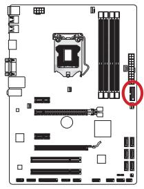
* The MB layout in this figure is for reference only.
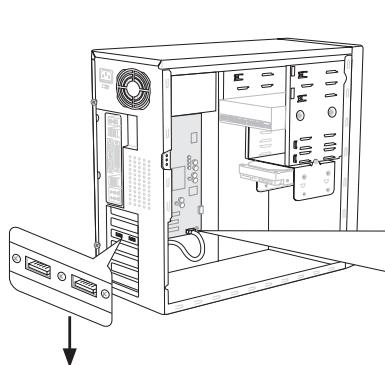
USB 3.0 Bracket (optional)

Important
- Note that the VCC and GND pins must be connected correctly to avoid possible damage.
- To use a USB 3.0 device, you must connect the device to a USB 3.0 port through an optional USB 3.0 compliant cable.
JUSB1~2: USB 2.0 Expansion Connectors
This connector is designed for connecting high-speed USB peripherals such as USB HDDs, digital cameras, MP3 players, printers, modems, and many others.


Important
Note that the VCC and GND pins must be connected correctly to avoid possible damage.
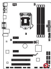
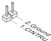
JCI1: Chassis Intrusion Connector
This connector connects to the chassis intrusion switch cable. If the computer case is opened, the chassis intrusion mechanism will be activated. The system will record this intrusion and a warning message will flash on screen. To clear the warning, you must enter the BIOS utility and clear the record.
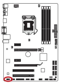
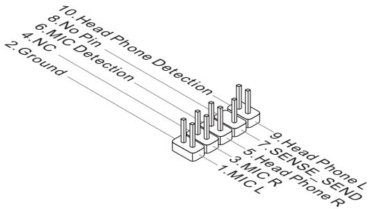
JAUD1: Front Panel Audio Connector
This connector allows you to connect the front audio panel located on your computer case. This connector is compliant with the Intel® Front Panel I/O Connectivity Design Guide.
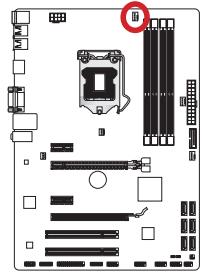
JTPM1: TPM Module Connector
This connector connects to a TPM (Trusted Platform Module). Please refer to the TPM security platform manual for more details and usages.
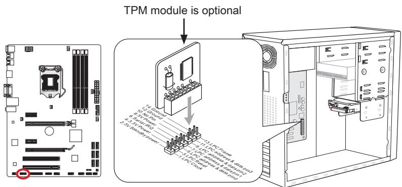
* The MB layout in this figure is for reference only.
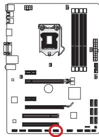
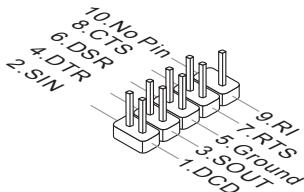
JCOM1: Serial Port Connector
This connector is a 16550A high speed communication port that sends/receives 16 bytes FIFOs. You can attach a serial device.
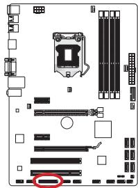
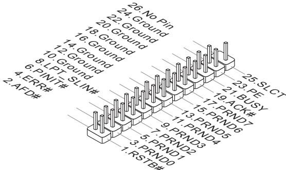
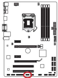
JLPT1: Parallel Port Connector
This connector is used to connect an optional parallel port bracket. The parallel port is a standard printer port that supports Enhanced Parallel Port (EPP) and Extended Capabilities Parallel Port (ECP) mode.
JDLED3: Voice Genie Connector (optional)
This connector is used to link to the voice control module (optional). Please refer to its user guide for more details and usages.
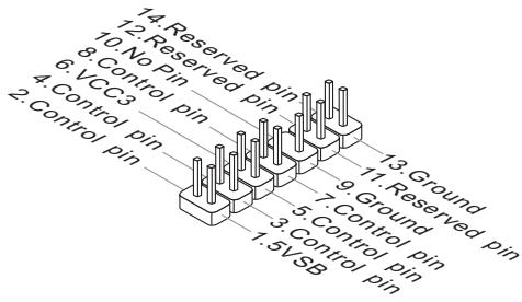
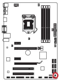
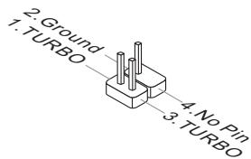
JTURBO1: MultiConnect Panel Connector (optional)
This connector is used to connect an optional front panel for controlling the OC Genie and some additional functions. Please refer to its user guide for more details and usages.
Jumper
JBAT1: Clear CMOS Jumper
There is CMOS RAM onboard that is external powered from a battery located on the mainboard to save system configuration data. With the CMOS RAM, the system can automatically boot into the operating system (OS) every time it is turned on. If you want to clear the system configuration, set the jumpers to clear the CMOS RAM.

Keep Data

Clear Data

Important
You can clear the CMOS RAM by shorting this jumper while the system is off. Afterwards, open the jumper. Do not clear the CMOS RAM while the system is on because it will damage the mainboard.
BIOS Setup
CLICK BIOS II is developed by MSI that provides a graphical user interface for setting parameters of BIOS by using the mouse and the keyboard.
With the CLICK BIOS II, users can change BIOS settings, monitor CPU temperature, select the boot device priority and view system information such as the CPU name, DRAM capacity, the OS version and the BIOS version. Users can import and export parameters data for backup or sharing with friends. After connecting to Internet, users can browse the internet, check mail and live update your system.
Entering
Power on the computer and the system will start POST (Power On Self Test) process. When the message below appears on the screen, press key to enter Setup.
Press DEL key to enter Setup Menu, F11 to enter Boot Menu
If the message disappears before you respond and you still wish to enter Setup, restart the system by turning it OFF and On or pressing the RESET button. You may also restart the system by simultaneously pressing <Ctrl> , <Alt> , and <Delete> keys.

Important
The items under each BIOS category described in this chapter are under continuous update for better system performance. Therefore, the description may be slightly different from the latest BIOS and should be held for reference only.
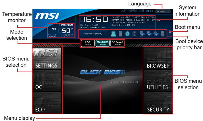
Overview
After entering Click BIOS II, the following screen is displayed.

Important
The pictures in this guide are for reference only and may vary from the product you purchased. Please refer to the actual screens of your system for detailed information.
Temperature monitor
This block shows the temperature of the processor and the mainboard.
System information
This block shows the time, date, CPU name, CPU frequency, DRAM frequency, DRAM capacity and the BIOS version.
BIOS menu selection
These blocks are used to select menus of BIOS. The following options are available:
- SETTINGS - Use this menu to specify your settings for chipset features, boot device.
- OC - This menu contains items of the frequency and voltage adjustments. Increasing the frequency can get better performance, however high frequency and heat can cause instability, we do not recommend general users to overclock.
ECO - This menu is related to energy-saving settings.
BROWSER - This feature is used to enter the MSI Winki web browser. - UTILITIES - This menu contains utilities for backup and update.
SECURITY - The security menu is used to keep unauthorized people from making any changes to the settings. You can use these security features to protect your system.
Boot device priority bar
You can move the device icons to change the boot priority.
Boot menu
This button is used to open a boot menu. Click the item to boot the system from the device instantly.
Mode selection
This feature allows you to load presets of energy saving or overclocking.
Menu display
This area provides BIOS settings and information to be configured.
Language
This allows you to select the language of the BIOS setting.
Boot device priority bar
This bar shows the priority of the boot devices. The lighted icons indicate that the devices are available.

Click and draw the icon to left or right to specify the boot priority.
Sub-Menu
If you find a point symbol to the left of certain fields, that means a sub-menu can be launched for additional options. You can use the arrow keys or mouse to highlight the field and press
If you want to return to the previous menu, just press
General Help
The General Help screen lists the appropriate keys to use for navigation. You can call up this screen from any menu by simply pressing
Operation
CLICK BIOS II allows you to control BIOS settings with the mouse and the keyboard. The following table lists and describes the hot keys and the mouse operations.
| Hot key | Mouse | Description |
| <↑↓→←> | Move the cursor | Select Item |
| <Enter> | Click/ Double-click the left button | Select Icon/ Field |
| <Esc> | Click the right button | Jump to the Exit menu or return to the previous from a submenu |
| <++> | Increase the numeric value or make changes | |
| <-> | Decrease the numeric value or make changes | |
| <F1> | General Help | |
| <F4> | CPU Specifications | |
| <F5> | Enter Memory-Z | |
| <F6> | Load optimized defaults | |
| <F8> | OC Profile Load From USB drive | |
| <F9> | OC Profile Save to USB drive | |
| <F10> | Save Change and Reset | |
| <F12> | Save a screenshot to a FAT/FAT32 USB drive |
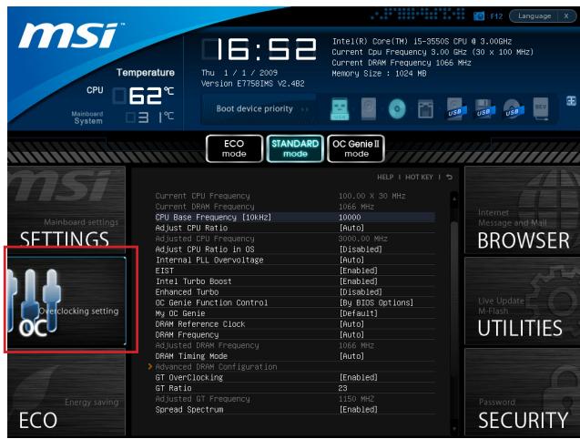
OC Menu
This menu is for advanced users who want to overclock the mainboard.

Important
- Overclocking your PC manually is only recommended for advanced users.
- Overclocking is not guaranteed, and if done improperly, can void your warranty or severely damage your hardware.
- If you are unfamiliar with overclocking, we advise you to use OC Genie for easy overclocking.
Current CPU/ DRAM Frequency
These items show the current clocks of CPU and Memory speed. Read-only.
CPU Base Frequency [10KHz]
Allows you to set the CPU Base clock (in 10KHz increments). You may overclock the CPU by adjusting this value. Please note that overclocking behavior and stability is not guaranteed.
Adjust CPU Ratio
Controls the multiplier that is used to determine internal clock speed of the processor. This feature can only be changed if the processor supports this function.
Adjusted CPU Frequency
It shows the adjusted CPU frequency. Read-only.
Adjust CPU Ratio in OS
Enable this item to allow CPU ratio changes in the OS by using MSI Control Center II.
Internal PLL Overvoltage
This item is used to adjust the PLL voltage.
EIST
Enhanced Intel SpeedStep technology allows you to set the performance level of the microprocessor whether the computer is running on battery or AC power. This field only appears with installed CPUs that support this technology.
Intel Turbo Boost
Enables or disables Intel Turbo Boost which automatically boosts CPU performance above rated specifications (when applications requests the highest performance state of the processor).
Enhanced Turbo
This feature was significantly enhanced on the CPU by allowing for speed to be increased to maximum frequency of Intel Turbo Boost for all CPU cores.
OC Genie Function Control
This item allows you to enable/ disable the OC Genie function.
My OC Genie
This item is used to select whether OC Genie parameters are customized by user. Setting to [Default] OC Genie will use default OC related parameters to overclock the system. Selecting [Customize] allows you to configure the following related "My OC Genie option" sub-menu manually for OC Genie.
My OC Genie option
Press
My OC Genie GT Overclocking
This item allows you to enable/ disable the overclocking of integrated graphics for OC Genie function.
My OC Genie GT Ratio
This item allows you to specific the GT ratio for OC Genie function.
Adjusted My OC Genie GT Frequency
It shows the iGPU frequency when OC Genie is started. Read-only.
DRAM Reference Clock
This item allows you to specify the DRAM Reference Clock for CPU. Please note the overclocking behavior is not guaranteed.
DRAM Frequency
This item allows you to adjust the DRAM frequency. Please note the overclocking behavior is not guaranteed.
Adjusted DRAM Frequency
It shows the adjusted DRAM frequency. Read-only.
DRAM Timing Mode
Select whether DRAM timing is controlled by the SPD (Serial Presence Detect) EEPROM on the DRAM module. Setting to [Auto] enables DRAM timings and the following "Advanced DRAM Configuration" sub-menu to be determined by BIOS based on the configurations on the SPD. Selecting [Link] or [Unlink] allows users to configure the DRAM timings for each channel and the following related "Advanced DRAM Configuration" sub-menu manually.
Advanced DRAM Configuration
Press
Command Rate
This setting controls the DRAM command rate.
tCL
Controls CAS latency which determines the timing delay (in clock cycles) of starting a read command after receiving data.
tRCD
Determines the timing of the transition from RAS (row address strobe) to CAS (column address strobe). The less clock cycles, the faster the DRAM performance.
tRP
Controls number of cycles for RAS (row address strobe) to be allowed to pre-charge. If insufficient time is allowed for RAS to accumulate before DRAM refresh, the DRAM may fail to retain data. This item applies only when synchronous DRAM is installed in the system.
tRAS
Determines the time RAS (row address strobe) takes to read from and write to memory cell.
tRFC
This setting determines the time RFC takes to read from and write to a memory cell.
tWR
Determines minimum time interval between end of write data burst and the start of a pre-charge command. Allows sense amplifiers to restore data to cell.
tWTR
Determines minimum time interval between the end of write data burst and the start of a column-read command; allows I/O gating to overdrive sense amplifies before read command starts.
tRRD
Specifies the active-to-active delay of different banks.
tRTP
Time interval between a read and a precharge command.
tFAW
This item is used to set the tFAW (four activate window delay) timing.
tWCL
This item is used to set the tWCL (Write CAS Latency) timing.
Advanced Channel 1/2 Timing Configuration
Press
GT OverClocking
This item allows you to enable/ disable the overclocking of integrated graphics.
GT Ratio
This setting controls the ratio of integrated graphics frequency to enable the integrated graphics to run at different frequency combinations.
Adjusted GT Frequency
It shows the iGPU frequency. Read-only.
Spread Spectrum
This function reduces the EMI (Electromagnetic Interference) generated by modulating clock generator pulses.

Important
- If you do not have any EMI problem, leave the setting at [Disabled] for optimal system stability and performance. But if you are plagued by EMI, select the value of Spread Spectrum for EMI reduction.
- The greater the Spread Spectrum value is, the greater the EMI is reduced, and the system will become less stable. For the most suitable Spread Spectrum value, please consult your local EMI regulation.
- Remember to disable Spread Spectrum if you are overclocking because even a slight jitter can introduce a temporary boost in clock speed which may just cause your overclocked processor to lock up.
CPU Core Voltage/ DRAM Voltage.
These items are used to adjust the voltages.
Current CPU Core Voltage/ Current DRAM Voltage
These items show current voltages. Read-only.
Overclocking Profiles
Press
Overclocking Profile 1/2/3/4/5/6
Press
Set Name for Overclocking Profile 1/2/3/4/5/6
Give a name by typing in this item.
Save Overclocking Profile 1/2/3/4/5/6
Save the current overclocking settings to ROM for selected profile.
Load/ Clear Overclocking Profile 1/2/3/4/5/6
Load/ Clear the stored profile settings from ROM.
OC Profile Save to USB
Save the current overclocking settings to USB flash disk.
OC Profile Load from USB
Load the stored settings from USB flash disk.
CPU Specifications
Press
CPU Technology Support
Press
MEMORY-Z
Press
DIMM1~4 Memory SPD
Press
CPU Features
Press
Active Processor Cores
This item allows you to select the number of active processor cores.
Limit CPUID Maximum
It is designed to limit the listed speed of the processor to older operating systems.
Execute Disable Bit
Can prevent certain classes of malicious "buffer overflow" attacks where worms can try to execute code to damage your system. It is recommended you keep this enabled always.
Intel Virtualization Tech
Enhances virtualization and allows the system to act as multiple virtual systems. See Intel's official website for more information.
Intel VT-D Tech
This item is used to enable/disable the Intel VT-D technology. For further information please refer to Intel's official website.
Power Technology
This item allows you to select the Intel Dynamic Power technology mode.
C1E Support
Enable system to reduce CPU power consumption while idle. Not all processors support Enhanced Halt state (C1E).
OverSpeed Protection
Monitors current CPU draw as well as power consumption; if it exceeds a certain level, the processor automatically reduces its clock speed. For overclocking, it is recommended this feature is disabled.
Intel C-State
C-state is a power management state that detects when the system is idle and lowers power consumption accordingly.
Package C State limit
This field allows you to select a C-state mode.
Long duration power limit (W)
This field allows you to adjust the TDP power limit for the long duration.
Long duration maintained (s)
This field allows you to adjust the maintaining time for long duration power limit.
Short duration power limit (W)
This field allows you to adjust the TDP power limit for the short duration.
Primary/ Secondary Plane Current Limit (A)
These fields allow you to adjust over current value limit of CPU (primary plane)/iGPU (secondary plane) for turbo ratio.
Primary/ Secondary plane Turbo Power Limit (W)
These fields allow you to adjust the turbo power limit of CPU (primary plane)/ iGPU (secondary plane) for turbo boost.
>1/2/3/4-Core Ratio Limit
These fields show the 1/2/3/4 core ratio limit of CPU.
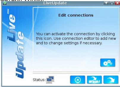
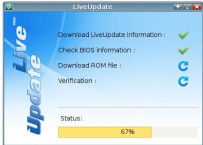
Updating the BIOS with Live Update
This section tells you how to update the BIOS by using the Live Update utility before entering Operating System. Live Update will update the BIOS automatically when connecting to the Internet. To update the BIOS with the Live Update utility:
- Click Live Update button on the BIOS UTILITIES menu. (The Winki must be installed).
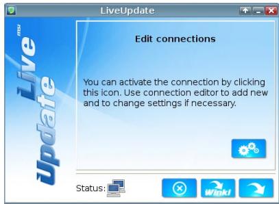
- Setup the connection by click the setting button if necessary.
- Click the next button
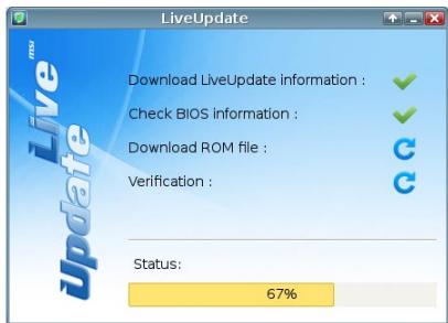
- Live Update will automatically detect the version of BIOS and download the appropriate file.
- Click the confirm button to update the BIOS.
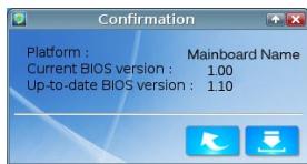
! Important
Do not update the BIOS if your system is running fine.
Software Information
Take out the Driver/Utility Disc that is included in the mainboard package, and place it into the optical drive. The installation will auto-run, simply click the driver or utility and follow the pop-up screen to complete the installation. The Driver/Utility Disc contains the:
- Driver menu : It provides available drivers. Install the driver by your desire and to activate the device.
- Utility menu : It allows you to install the available software applications.
- Service base menu : Through this menu to link the MSI officially website.
- Product info menu : It shows the newly information of MSI product.
- Security menu : It provides the useful antivirus program.

Important
Please visit the MSI officially website to get the latest drivers and BIOS for better system performance.
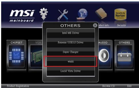
Installing Winki
BIOS BROWSER and UTILITIES request Winki, please install the "Winki" software application from MSI Driver Disc in Windows first. And then you can access these two features by clicking their respective buttons.
To install Winki, follow the steps below:

- Power on your computer and enter Windows operating system.
- Insert MSI Driver Disc into the optical drive. The setup screen will automatically appear.
- Click Driver tab.
- Click OTHERS button.
- Select Winki to start installing.
- When finished, restart your computer.

Deutsch
Z77A-G41/
ZH77A-G41/
B75A-G41 Serie
Spezifikationen
Prozessoren
http://www.msi.com/service/cpu-support

CPU & Cooler Installation
JFP1, JFP2: Frontpanel Anschlüsse
CPU Base Frequency [10KHz]
Adjusted CPU Frequency
Adjust CPU Ratio in OS
Adjusted My OC Genie GT Frequency
Adjusted DRAM Frequency
Adjusted GT Frequency
Set Name for Overclocking Profile 1/2/3/4/5/6
CPU Technology Support
OverSpeed Protection
> Long duration power limit (W)
> Long duration maintained (s)
> Short duration power limit (W)
Primary/ Secondary Plane Current value (A)
Primary/ Secondary plane turbo power limit (W)
Supporte le mode double-canal
LAN
http://www.msi.com/service/cpu-support

Emplacement PCIe (Peripheral Component Interconnect Express)
Emplacement PCI (Peripheral Component Interconnect)
Current CPU/ DRAM Frequency
CPU Base Frequency [10KHz]
Adjusted CPU Frequency
Adjust CPU Ratio in OS
Adjusted My OC Genie GT Frequency
Adjusted DRAM Frequency
Advanced Channel 1/2 Timing Configuration
Adjusted GT Frequency
Current CPU Core Voltage/ Current DRAM Voltage
Set Name for Overclocking Profile 1/2/3/4/5/6
CPU Technology Support
Active Processor Cores
Intel Virtualization Tech
OverSpeed Protection
Package C State limit
> Long duration power limit (W)
> Long duration maintained (s)
> Short duration power limit (W)
Primary/ Secondary Plane Current Limit (A)
Primary/ Secondary plane Turbo Power Limit (W)
YcTaHOBKa LII N BcHTnJIaTOpa
Pn yctaHOBke npoecccopa o63aTeIbHO yCTaHOBITE BeHTnIaTOp LII. BeHTnIaTOp LII npedynpeKdaet neperepbaeHne I obecneuHbae T cAubhOcTB paobtbcntembl. HnKe npedctabIeHbI INCTpyKcunn no npabInbHOy yCTaHOBKE npoecccopa n BeHTnIaTOp LII. HenpaBnJIbHaay yCTaHOBka npnbOanr K BbIXOy n3 CTpo npoecccopa m MaTePNHCKO nnatbl.
- OTuEInTe nIPOJIHOCTbIO IOnHIMMITEpbHuar fIKCaunn.

- AkkypaTHO yCTAHOBITE npoceccop B COOTBETCTBtuOuEe rHe3do. DepeKHTe npoceccop 3a OCHOBaHne, HAnpaBnB MeTaNIIueCKNe KOHTaKTbI Bn3. Pn npaBnJIbHOY cTaHOBKe 3HaKn COBMeUeHnHa npoceccope DoJHKhbl COBnAdaTb C KpAMyrHe3da DnI npoceccopa.
- Пи подьеме рьчara Фнкаци вВТOMATЧЕСКИ NOДНИМАЕТСЯ 3a- rpy3Oуня пл actина. He Tporaite KOHTAKTBI yCTAHOBQUHoi nAHeJI Npoceccopa.
- 3akpoTe 3aRpy3OCHyIO pIaCTnHy IN CHIMITE 3aUHTbI IJIaCTIKOBbl KONpaQOK.
- Поберпе Наджноctь установкиnpоцсopaВ COOTBETCTBYHIOCEmгзд.ОпунтTe BnI3pbIyarФИКациN 3akpenTe erO 3a yшкokpючka ФИКcaциN.

- HauDnte pa3bem dIy BeHTnIaTopa LII Ha MaTeepHcKo INaTe.

- PabHOMePHO HaHeCnTe ToHKn CNoI TepMonactbI (NII IN TepMOJeHTy)Ha BepXHIOI paHeJIb IpoCeccopa. 3To N03BOJAEYBEnuHTb TeNlOpeDaUy I pEduynpeKdaET nepepeBaHne IpoCeccopa.

- UctaHOBnTe paDnAtOp Ha MaTePnHCKyIO pIaTy, HAnpabN B erO npoBOnaB CTOpOHy pa3bema IЯ BEHTnIaTOp a N COBMeUaJ KpUcK C OTBePCTnYMa B MaTePnHcKoi PIIate.

- Haxmte Ha padnatopt cbepy TaK, TTo6bI 3aKepeNTb YeTbpe 3aueen- Kn B OTBepCTnX Ha MaTePunHcKo nIaTe. Haxmte Ha 3aueenKn dJa 3aKepeJIeHn BENTnJtopa. KaJdbI n3 KpOuKOB 3aKepeNJaETc JaelKOM.
- Ocmotpnte MaTePHNcKyI pIaTy I onpeJeIInTe npaBnJIbHocTb 3akpen- JENHIA 3axmOB.

THe3da nIy INaTbI paCUnpeHnY
Данна MaTePNHcKa ПЛATA COePKeNT MHOXeCTBO pa3bEmOB ДЯ yCtahOBKN ПЛATpacшерпя,在BчactHOctN,ДИСКрTeHbIX BnDEoKapT ININ 3ByKobblx KapT.
Гнебу PCIe (Peripheral Component Interconnect Express)
Tne3do PCIe noidepkmbaet nla tabi paacunpeHn c nHTepfeom PCIe.

Tne3Do PCIe 3.0 x16
Tne3do PCle 2.0 x16
Гнeftо PCIe 2.0 x1
ГнебоPCI(Peripheral Component Interconnect)
Ihe3doPCI no3boJareyctahOBHTnPaTbJIBC,SCSI,USBnDpyrHe donoHnteHbHbI pacuipenHnKOTOpBcOoTBetCTByOT cneunPkaCnn PCI.
32-pa3pIHoe rHe3do PCI

BhimaHxie!
Ipepe yctahOBKO nn n3BneHem nnat paCunpeHn y6eNTecb, YTO shyp nHTaHn OTKIOUeH OT 3NEKTPuuecko CETn. IpoTuTE DOkymentauNHO h KapTy paCUnpeH N BblONHtE HeOxOuMbIe DOnONHtEnbHbIe aAnnapaTHbIe nn nporpaMMhIe N3MeHeHn dJa daHNo KApTbI.
MapuTy3aun 3anpocnpepbvban PCI
Current CPU / DRAM Frequency
Данные сименты OTOBражад.TaKTOBYU YacToTу npOceccopa И bIcTpOeIcTBne namTи.ЗТо 3HAueHHe Nelb3Я ИЗмeHЯть.
CPU Base Frequency [10KHz]
DanHnaOpnCnyKInIyraYCTaHOBKn6a3OBOI TaKTOBOn YactOTbI LITcWArOMB 10KtU).M3MeHHeN3TOro npaAMTePa o6ecneuBaet BO3MOXHOCTb «pa3roHa」LIT. O6paJaeMaBe BAmE BmHAnHe Ha To, YoTo KOMNaHn He rapaHTpyeYcNeuHOCTb Bbl- nonJIHHeNpa3rOHa n Cta6BnHObCTb CnCTeMbI.
Adjust CPU Ratio
Данны параметр onpeдениг MHOЖITENь, ИСОпь3уЕмь дяп ONрденигИТAKTOВЧАТOTБI pOUECCOPA.ИЗмение dAnHORO napamETBa 03MOKHO TOnBkoВ Tom Clyuae, ecIn prouceccop noДерхиBaet DaHNYФУKHUNIO.
Adjusted CPU Frequency
3TOT nyHKT nOKa3bIbaeTeKuyu Yo cactoty LII. 3To 3HaueHHe HeIb3r I3MeHArTb.
Adjust CPU Ratio in OS
AknBpyNe DaHHyO OpiuO IJI BHeCehnB OC n3MeHEn MHOKeTJI npocecco pa uepe3 MSI Control Center II.
Internal PLL Overvoltage
Данн布局паметерспспьзетдярergyлpopбинаржениФAPU(PLL).
EIST
TexHONorIy Enhanced Intel SpeedStep no3BOJIeT yCTaHOBITb yPoBeHb npOn3BOJInTeNbHocTN MKNpOnpoCeCCopa npn 3JIeKTPoNtAHm OT baTapeHn OT cETn. DaHHoe nOle OTo6paXaEcTc TOnbKO B TOM Clyuae, ecn yCTaHOBJIeHHbIe npOceCCOpb INoDepKxNBaIOT 3Ty TexHONorIy.
Intel Turbo Boost
Данная коньа сухит дя вкюуняил оTKюуняпхонори Intel Turbo Boost, kotopая abTomatчесkn nobblaaset bblseуka3aHHble xapaktepructNKи npoI3BOIDNTeHbHocTи LП (eclin dЯ pa6Otbl npinnoxehny Tpe6yetycmaKcIMaJIbHЯ npoI3BOIDNTeHbHocTb npoceccopa).
Enhanced Turbo
3haHTeIbHO yUyueHa daHHa fHKnB INpoceccope. 3TO nO3BOJraT NOBicITb CKOpocTb do MaKcImaJIbHO uactotbl Intel Turbo Boost dner Bcxex Jdep npoeccopa.
OC Genie Function Control
Adjusted My OC Genie GT Frequency
Adjusted DRAM Frequency
3TOT nyHKT noka3bIbaeTe Kcyu yu cactOy DRAM. 3To 3HaueHHe HnB3a IN3MeHrTb.
DRAM Timing Mode
3TOT nyHKT onpeJeIeT, 6yUyt IIN BVPemHbIe npaMeTpbl DRAM KOHTPOINPOBaTbcAanHbIMn n3 SPD (Serial Presence Detect) EEPROM Ha moDyne DRAM. PnB bIbOpe pexima [Auto (ABTO)] BkNIOaTeC Tc HxPOH3aZnR DRAM, a B noDMEno "AdvancedDRAM Configuration" BIOS yCTaHaBInBaET npaMeTpbl Ha oChOBe xapakTePncTnk SPD. BbIbOp pexima [Link (CoEduINHtB)] nII [Unlink (Pa3bEduHNtB)] no3BOJnEe TnoIb3OBaTeIIO hAcTpaMaBt CnHXPOH3aZnIO DRAM dJIa KAKDo rKaHaJa N BrpyHuO nepexOJNTB B noDMHeIO «Advanced DRAM Configuration».
Advanced DRAM Configuration
Haxmnte
Command Rate
Danhnay hactpoiKa onpeJeIeRt cKOpocTb BbInOnHeHnKoMaHd DRAM.
tCL
3Ta KhoNka ynpabnreT BpeMeHem OxndaHnca CAS, KOtOpoe onpeJeIeRbBpeM 3aepKm (B TaKTax) MeJdy nOlyuHHeM DaHHbIX N HaCaJIOM BblIOJIHeHnKaOMaHdbl YuTeHnra.
tRCD
3ta Khonka onpeedjare Bpemn nepexoja ot RAS (ctpo6 apeca ctpokn) K CAS (ctpo6 apeca ctonbca). Yem Mehbe TAKTOB, Tem 6bictpee pa60aet namrTb DRAM.
tRP
3Ta KhoNka ynpabnreT KOJIueCTBOM TaKToB, npEoocTabIeMbIX nI pyed3apraJa CTo6Ba aDpeca cTpOKn (RAS). Ecnn BbIeJenrTeC hEDOCtatoHoe BpeMn dIa 3aONHeHRA SNepei o6HOBJeHem DRAM, DRAM He cMOxet CoXpaHITb daH Hbe. 3TOT NyHKT npIMeHm, KOrDa B CNTeMe yCTaHOBJeHa CNHXPOHHa NaMrtb DRAM.
tRAS
3Ta KhoNka onpeJeIeT BpeM, KOtopoe RAS (cTpo6 aIpeca cTPOK) 3aTpaHbAeHa YTeHne I 3aNNbc B JYeKy nAMrTn.
tRFC
3TOT nyHKT onpeedelaet Bpem, KOtOpoe RFC 3aTpauNbaeT ha YteHne n 3aPiNcB Byaey Ky naMAn.
tWR
Данная конка onpeдяет MINHMaIbHbI npomexyToKВpeMeHn ДЯ BbINONHeNHa Onerpaци 3aInci nepeK komaHDoJ nped3apJa. ПОЗьлгет усИnteЯM CHTbBaHnA 3aIncaTb DaHhIeB YaeyKn namrTn.
tWTR
Adjusted GT Frequency
OTo6pakaetcaJcTaIaGPU.3To 3HaueHHe HeJIb3a NImeHrTb.
Spread Spectrum
Current CPU Core Voltage/ Current DRAM Voltage
Данные napametpbI NOka3bIBaHT Tekyuee HapryxeHne. 3To 3naueHne HeJIb3Я n3MeHЯТь.
Overclocking Profiles
Haxmnte
Overclocking Profile 1/2/3/4/5/6
Haxmnte
Set Name for Overclocking Profile 1/2/3/4/5/6
3aainTe mB daHOM nOJe.
Save Overclocking Profile 1/2/3/4/5/6
CoxpaHHe NteKyuInx npaMeTpoB pa3roHa IJI BbIbpaHoro npoФnIa Ha 3Y
Load/ Clear Overclocking Profile 1/2/3/4/5/6
3arpy3ka/YdaneHne coxpaneHHbIX B p3Y npapametpoB npocnna.
OC Profile Save to USB
CoxpaHHeNt Ekyuixn npaMeTpOB pa3rOHa Ha qJIms-HakOnnteJe.
OC Profile Load from USB
3arpyka coxpaehHHbIX npaMeTpOB HacTpoKnC 0JIaHakonnteJra.
CPU Specifications
HaxMMTe
CPU Technology Support
Haxmte 一 Enter> nI BxAOa B noMHeIO. B daHHOM noMHeIO oTo6paKaIoTcA yHKuyn yCTAHOBnEHoro npoecccopa. 3Tu 3HaueHn HeJIb3r N3MeHnTb.
MEMORY-Z
Haxmte
DIMM1~4 Memory SPD
Haxmte
CPU Features
Haxmnte
Active Processor Cores
3TOT NyHKT N03B0JRAET 3aDaT b YNCIO aKTHBbIX Jaep npoceccopa.
Limit CPUID Maximum
Данньий napametprnpedHa3haueHдяогранчehняdonyctmmockopoctn npo- ceccopa priu nCnoJIb3OBAHN CTapbIX Bercn OC.
Execute Disable Bit
I03B0JraET 3aUHTbcra OT HeKOTOpbIX BUNO3 3NoHAmpeHHbIX DeiCTBn TIna «OoN6Kn NepenOnHeHna 6yΦepa», npn KOTOpbIX BnpycblbTaHOcra BblNOJHnTb kOd, pa3pyuHaOuIcnCtEmy. PekOMeHdyEYcra He OTKIQUaTb daHHyIO fYHKUIO.
Intel Virtualization Tech
Ynyuwaet 3ofoekntHBocTh BnptyaIIN3aunN IIO3BOJrae TcCTEm BbIOnHrTb
fynKcn HeckOJIbKnx BnptyaJIbHbIX CnCTem. DOnOJIHnTeJIbHbIe CBeJeHHa CM. Ha
OoNuaJBHom Be6-caTe Intel.
Intel VT-D Tech
3TOT nyHKT nCnOJb3yETcA IINB KJIIOUeHn/BykIIOUeHn TExHOrONn Intel VT-D. DOnoHNHeJIbHbIe CBeDeHn CM. Ha OΦuIaJIbHOM Be6-CaITe Intel.
Power Technology
OverSpeed Protection
KoHTpOJIuPyET BbIcNlnteBHyIO Harpy3ky u 3HeproNoTpe6IeHne LIT; npn ppeBblIeHN OnpeDeIeHHoro yPOBn IpoUeCCOP ATOMaTHueCKN IOHIXaET TaKTOByIO YactOTy. PnB bIInONHeHnn pa3rOHa CnCTeMb peKOMeHdyETcR OTKIIouaTb DaHHyIO fYHKsIO.
Intel C-State
C-state 3TO TexHONOrn ynpabNeHn NtAnHeM, npu KOTOpO 3NaUHTeJIbHO cokpaaetc3 Hepronotpe6IeHne npoecccopa npn npocToe cnCTembl.
Package C State limit
> Long duration power limit (W)
Даннь паметр IncnoIb3уетс ду yctahOBk MaKcmaJIbHOro TDP npouecccopa dny dInTeIbHO pa60tbl.
> Long duration maintained (s)
B daHOM none yka3bIbaeTcMAKcImaJIbHOe Bpempa6oTe bI npouecoppa c orpaHnueHHeM MoUHcToN pRn dInTeJIbHOM yCKOpEHn.
Short duration power limit (W)
B daHOM nOJe yCTaHaBnBaetc npedeIbHa MaOuHocTb TDP npKpaTKOBpeMeHHOM yCKOpEHn.
Primary/ Secondary Plane Current Limit (A)
3TN noJII no3BOJIAOT yCTaHOBnTb 3HaueHne CBepxTOKOB LII (MaKcImaJIbHaJ MOU-HocTb)/IGPU (BtOpuHbI ppeDen) IJI K03ΦΦnIeHTa YCKopeHnI.
Primary/ Secondary plane Turbo Power Limit (W)
3TN noJr no3BOJYOT yCTaHOBnTb npedeJIbHoe 3NaYeHne MoUHocTn npOeCCopa B pexKIme Turbo (MaKcIMaJIbHa rMoUHocTb)/ iGPU (BToPnHbI npDeJI) B pexKIme turbo boost.
>1/2/3/4-Core Ratio Limit
Даанные паметрblоTOбражOTOrpaHиЕне уСКОпЕНЯТAKТОВОЧАСТОТыnpоцeccopaВсИСтeme1/2/3/4ядра.
OboBHeHneBIOSc nOoBIOMoynLiveUpdate
B daHnom pa3eJe paccKa3bIaebTcO npRKe o6HOBJIeHnBIOS c nOMoUbO yTuINtBi Live Update nepeB BXoDM B onepaunOHny CnCTeMy. Ppi NpOKJIuChENK INTEPHeTy yTuINtTa Live Update BblONHReT ABTomatueckoe 6HOBJIeHnBIOS. IInr o6HOBJIeHnBIOS c nOMoUbMoDyLn Live Update:
- Haxmnte Ha KhoNky Live Update B MeHIO BIOS YTNJNTbl. (Tpe6yeTcra yctaHOBka Be6-06o3peBaTeIe Winki).
- Пин HeobxOIOMOCTN HaxMnte Ha KHOIpKu HAcTpOoi n yctaHOBInTe coeHnHeHne.
- Haxmnte Ha KhoNky Next (Danee)
- Ytuna Live Update abTomatueckn BbIopHaeT nonck Bepcn BIOS n 3arpy3ky cooTBETCTByoJero daJa.
- Haxmnte ha kHONky confirm (noTBePntb) Iy o6HOBneHnBIOS.


Ppi6ecpebeohno paote cncTeMbIObHOBnHe BIOS He bInonHraTcA.
CBeHeHnO npOrpaMMHom oBeCeueHn
YctAHOBnTE B pIINBOD OTNNUeCKNX DnCKOB PpIINAeAMbIK CnCTeMHOn NnATEKOMNaKT nDnCK «Driver/Utility」.UcTahOBKa 3aIyCTNTcABTOMATNuCeKn. Bbl6epTe DpaJIbEP INn CnyKe6hHyo npOrpAmMy nCneJyTe INHCTpyKuIma N haKpaHe IJN 3aBepSeHnry yCTaHOBKn. CoedeXHMoe Dis-dnckca C dpaiBepAMn IN cyKe6hBlmnporpAMMaM:
- Driver menu (Mehio npaiBepo): Ha hem codepkaTcdoctynhIe dpaiBepbl. IyncnoJIb3OBAHnY yCTpoiCTBa yCTaHOBnte HxKbI dpaiBep.
- Utility menu (Служебные nporpammbi): ДИСК ПОЗВЛЯТ yCTaHOBnTB ИМЕЮДЕСА На НEM пикладhoe nporpamMHoe обесенье.
-Service base menu (CepBnchbIe nporpaMMbl): C nomoIbu DaHHO MeHO MoKHO BmTu Ha oOpuHaJIbHbI Be6-caIT KOMNaHIM MSI.
- Product info menu (Информацьу о пюдкт): Oтохражается постенья Информацьи по пюдкту komпанни MSI.
- Security Menu (Мени Бezonaachoctь): CodepЖNT NOJIe3HyIO aHTNBpycHyIO nporpaMMy.

BhimaHne!
Длл получени полднх Верси драиьеров И мкрponporpaMM BIOS, no3BoJI KUxH NOBicNTb npOIN3BOIDHTeJIbHOCTb CnCTeMbI, obpaцайтecь наофицальньИ Be6-caIT komnaHmMSI.
YctaHOBka Winki
Дя pa6obtby O5O3PEBATEЯ n YTINIT BIOS tpe6yetc Winki. Chaayala yctahOBITE nporpamMHOe npinIOxenge "Winki" c dncka c dpaBepam MSI Driver Disc BOC Windows. 3aTe m hKmMaTe Ha coOTBeTCTByUoJne KHONKn IЯ BXOda B 3TN DBeФунки.
IyctaHOBKn Winki BbInONHnTe CneDyIOUne DeiCTBnJr
- BkIIOHTe NITaHHe KOMIbIOTepa I BOIaIte B ONEpaOHHyIO CnCTeMy Windows.
- BCTaBbTe Dnck C dpaBepamM MSI Driver Disc B npNBOd IJRA ONTuecknx IuCKOB. ABTOMATueckn OTO6paxaetc 3KpaH yCTaHOBKn.
- ⅢeIKNHnTe Ha BkJaDke paaiBepa.
- Haxmte Ha KhoNky OTHERS (Dpyne).
- Дянaya установки Вьберпte Winki.
- Iocne 3aBepseHn yctaHOBN BbINOHNTE nepe3arpy3ky KOMNbIOpeta.