MS-7660 - Motherboard MSI - Free user manual and instructions
Find the device manual for free MS-7660 MSI in PDF.
User questions about MS-7660 MSI
0 question about this device. Answer the ones you know or ask your own.
Ask a new question about this device
Download the instructions for your Motherboard in PDF format for free! Find your manual MS-7660 - MSI and take your electronic device back in hand. On this page are published all the documents necessary for the use of your device. MS-7660 by MSI.
USER MANUAL MS-7660 MSI
Power Edition series
MS-7660 (v1.x) Mainboard
Copyright Notice
The material in this document is the intellectual property of MICRO-STAR INTERNATIONAL. We take every care in the preparation of this document, but no guarantee is given as to the correctness of its contents. Our products are under continual improvement and we reserve the right to make changes without notice.
Trademarks
All trademarks are the properties of their respective owners.
MSI is registered trademark of Micro-Star Int'l Co., Ltd.
NVIDIA® is registered trademark of NVIDIA Corporation.
ATI® is registered trademark of ATI Technologies, Inc.
AMD® is registered trademarks of AMD Corporation.
Intel® is registered trademarks of Intel Corporation.
Windows® is registered trademarks of Microsoft Corporation.
AMI is registered trademark of American Megatrends, Inc.
Award® is a registered trademark of Phoenix Technologies Ltd.
Sound Blaster® is registered trademark of Creative Technology Ltd.
Realtek® is registered trademark of Realtek Semiconductor Corporation.
- JMicron® is registered trademark of JMicron Technology Corporation.
Netware® is a registered trademark of Novell, Inc.
Lucid® is trademarks of LucidLogix Technologies, Ltd.
Revision History
| Revision | Revision History | Date |
| V1.0 | Release for PCB 1.X (Europe version) | July 2010 |
Technical Support
If a problem arises with your system and no solution can be obtained from the user's manual, please contact your place of purchase or local distributor. Alternatively, please try the following help resources for further guidance.
Visit the MSI website for FAQ, technical guide, BIOS updates, driver updates, and other information: http://www.msi.com/index.php?func=service
Contact our technical staff at: http://ocss.msi.com
Safety Instructions
Always read the safety instructions carefully.
- Keep this User's Manual for future reference.
- Keep this equipment away from humidity.
Lay this equipment on a reliable flat surface before setting it up.
- The openings on the enclosure are for air convection hence protects the equipment from overheating. DO NOT COVER THE OPENINGS.
- Make sure the voltage of the power source and adjust properly 110/220V before connecting the equipment to the power inlet.
- Place the power cord such a way that people can not step on it. Do not place anything over the power cord.
Always Unplug the Power Cord before inserting any add-on card or module.
All cautions and warnings on the equipment should be noted.
- Never pour any liquid into the opening that could damage or cause electrical shock.
If any of the following situations arises, get the equipment checked by service personnel:
The power cord or plug is damaged.
Liquid has penetrated into the equipment.
The equipment has been exposed to moisture.
The equipment does not work well or you can not get it work according to User's Manual.
The equipment has dropped and damaged.
The equipment has obvious sign of breakage.
DO NOT LEAVE THIS EQUIPMENT IN AN ENVIRONMENT UNCONDITIONED, STORAGE TEMPERATURE ABOVE 60^ (140°F), IT MAY DAMAGE THE EQUIPMENT.
CAUTION: Danger of explosion if battery is incorrectly replaced.
Replace only with the same or equivalent type recommended by the manufacturer.
警告使用者:
For better environmental protection, waste batteries should be collected separately for recycling special disposal.
FCC-B Radio Frequency Interference Statement
This equipment has been tested and found to comply with the limits for a Class B digital device, pursuant to Part 15 of the FCC Rules. These limits are designed to provide reasonable protection against harmful inter

ference in a residential installation. This equipment generates, uses and can radiate radio frequency energy and, if not installed and used in accordance with the instructions, may cause harmful interference to radio communications. However, there is no guarantee that interference will not occur in a particular installation. If this equipment does cause harmful interference to radio or television reception, which can be determined by turning the equipment off and on, the user is encouraged to try to correct the interference by one or more of the measures listed below.
Reorient or relocate the receiving antenna.
- Increase the separation between the equipment and receiver.
- Connect the equipment into an outlet on a circuit different from that to which the receiver is connected.
Consult the dealer or an experienced radio/television technician for help.
Notice 1
The changes or modifications not expressly approved by the party responsible for compliance could void the user's authority to operate the equipment.
Notice 2
Shielded interface cables and A.C. power cord, if any, must be used in order to comply with the emission limits.
VOIR LA NOTICE D'INSTALLATION AVANT DE RACCORDER AU RESEAU.

Micro-Star International
MS-7660
This device complies with Part 15 of the FCC Rules. Operation is subject to the following two conditions:
1) this device may not cause harmful interference, and
2) this device must accept any interference received, including interference that may cause undesired operation.
WEEE (Waste Electrical and Electronic Equipment) Statement
ENGLISH
To protect the global environment and as an environmentalist, MSI must remind you that...
Under the European Union ("EU") Directive on Waste Electrical and Electronic Equipment, Directive 2002/96/EC, which takes effect on August 13, 2005, products of "electrical and electronic equipment" cannot be discarded
as municipal waste anymore and manufacturers of covered electronic equip-
ment will be obligated to take back such products at the end of their useful life. MSI will comply with the product take back requirements at the end of life of MSI-branded products that are sold into the EU. You can return these products to local collection points.

DEUTSCH
Power Edition Series
Mainboard Specifications
Processor Support
- AMD® Phenom™ II series, Athlon™ II series and Sempron™ series processor in the AM3 package. (For the latest information about CPU, please visit http://www.msi.com/index.php?func=cpuform2)
HyperTransport
HyperTransport™ 3.0, supports up to 5.2 GT/s
Chipset
North Bridge: AMD® RX780 chipset
- South Bridge: AMD® SB850/ SB810 chipset
Lucid® LT22102
Memory Support
DDR3 1600 (OC) / 1333 / 1066 DRAM (total 16GB Max)
- 4 DDR3 DIMMs, supports Dual-Channel mode
* (For more information on compatible components, please visit http://www.msi.com/index.php?func=testreport)
LAN
Supports PCIE LAN (10/100/1000) by Realtek® RTL8111DL
IEEE 1394
Chip integrated by VIA® VT6315N
Supports 1 IEEE 1394 port (back panel) & 1 IEEE 1394 connector
Audio
- HD audio codec integrated by Realtek® ALC892/ ALC889
Flexible 8-channel audio with jack sensing
SATA
6 SATA 6Gb/s ports by AMD® SB850
Or 6 SATA 3Gb/s ports by AMD® SB810
Supports hot plug & asynchronous notification
USB 3.0
2 USB 3.0 ports by NEC uPD720200F1
RAID
SATA1~6 ports support RAID 0/1/5/10 mode by AMD® SB850
Or SATA1~6 ports support RAID 0/1/10 mode by AMD®SB810
Connectors
Back panel
- 1 PS/2 keyboard port
- 1 PS/2 mouse port
- 1 Clear CMOS button
- 1 Coaxial S/PDIF-Out port
- 1 Optical S/PDIF-Out port
- 6 USB 2.0 ports
- 1 USB 3.0 port
- 1 IEEE 1394 port
- 1 LAN port
- 6 flexible audio ports
On-Board
- 3 USB 2.0 connectors
- 1 USB 3.0 connector
- 1 IEEE 1394 connector
- 1 Chassis Intrusion connector
- 1 S/PDIF-Out connector
- 1 Front Panel Audio connector
- 1 Serial Port connector
- 1 TPM Module connector
- 1 Power button
- 1 Reset button
- 1 Green Power button
- 1 OC Genie button
Slots
2 PCIE x16 slots
- Supports Multi-GPU computing technology
Supports ATI CrossFireX™ technology
3 PCIE x1 slots
1 PCI slot, supports 3.3V/ 5V PCI bus Interface
Form Factor
ATX (24.5cm X 30.5 cm)
Mounting
9 mounting holes
- If you need to purchase accessories and request the part numbers, you could search the product web page and find details on our web address http://www.msi.com/index.php
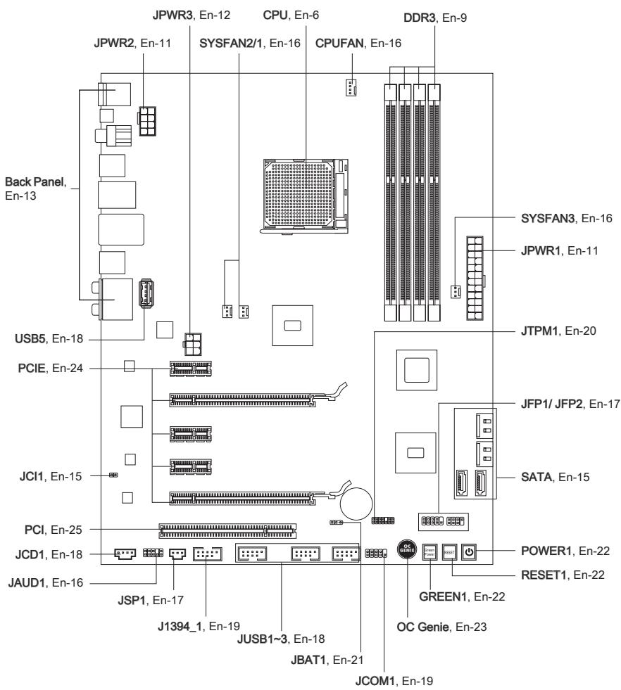
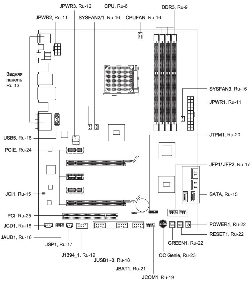
Quick Components Guide
Screw Holes
When you install the mainboard, you have to place the mainboard into the chassis in the correct direction. The locations of screws holes on the mainboard are shown as below.
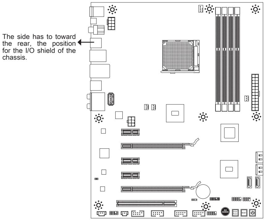
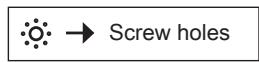
Refer above picture to install standoffs in the appropriate locations on chassis and then screw through the mainboard screw holes into the standoffs.
Important
- To prevent damage to the mainboard, any contact between the mainboard circuit and chassis or unnecessary standoffs mounted on the chassis is prohibited.
- Please make sure there are no metal components placed on the mainboard or within the chassis that may cause short circuit of the mainboard.
CPU (Central Processing Unit)
When you are installing the CPU, make sure to install the cooler to prevent overheating. If you do not have the CPU cooler, consult your dealer before turning on the computer. For the latest information about CPU, please visit http://www.msi.com/index.php?func=cpuform2
Important
Overheating
Overheating will seriously damage the CPU and system. Always make sure the cooling fan can work properly to protect the CPU from overheating. Make sure that you apply an even layer of thermal paste (or thermal tape) between the CPU and the heatsink to enhance heat dissipation.
Replacing the CPU
While replacing the CPU, always turn off the ATX power supply or unplug the power supply's power cord from the grounded outlet first to ensure the safety of CPU.
Overclocking
This mainboard is designed to support overclocking. However, please make sure your components are able to tolerate such abnormal setting, while doing overclocking. Any attempt to operate beyond product specifications is not recommended. We do not guarantee the damages or risks caused by inadequate operation or beyond product specifications.
Introduction to AM3 CPU
The surface of CPU. Remember to apply some thermal paste on it for better heat dispersion.
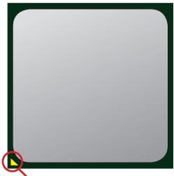
Gold arrow
CPU & Cooler Installation
When you are installing the CPU, make sure the CPU has a cooler attached on the top to prevent overheating. Meanwhile, do not forget to apply some thermal paste on CPU before installing the heat sink/cooler fan for better heat dispersion.
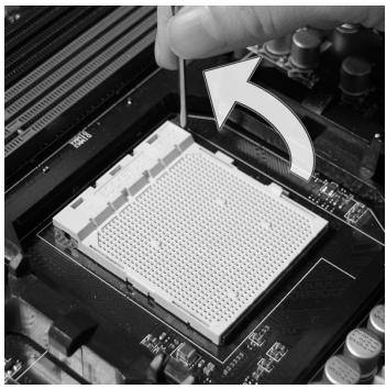
Follow the steps below to install the CPU & cooler correctly. Wrong installation will cause the damage of your CPU & mainboard
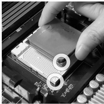
- Pull the lever sideways away from the socket. Make sure to raise the lever up to a 90-degree angle.
- If the CPU is correctly installed, the pins should be completely embedded into the socket and can not be seen. Please note that any violation of the correct installation procedures may cause permanent damages to your mainboard.
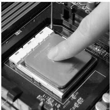
- Look for the gold arrow of the CPU. The gold arrow should point as shown in the picture. The CPU can only fit in the correct orientation.
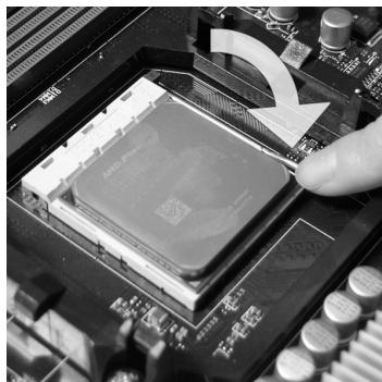
- Press the CPU down firmly into the socket and close the lever. As the CPU is likely to move while the lever is being closed, always close the lever with your fingers pressing tightly on top of the CPU to make sure the CPU is properly and completely embedded into the socket.
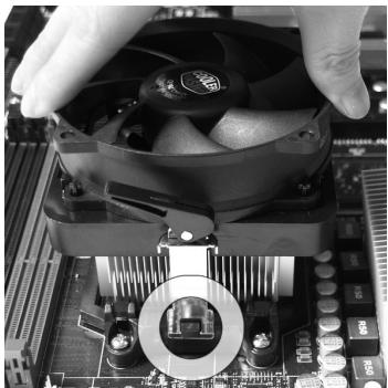
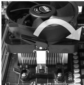
- Position the cooling set onto the retention mechanism.
Hook one end of the clip to hook first.
- Fasten down the lever.
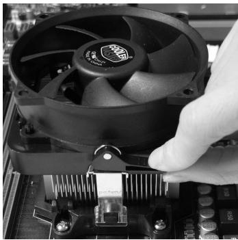
- Then press down the other end of the clip to fasten the cooling set on the top of the retention mechanism.
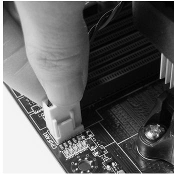
Locate the Fix Lever and lift up it.
- Attach the CPU Fan cable to the CPU fan connector on the mainboard.
Important
- Mainboard photos shown in this section are for demonstration only. The appearance of your mainboard may vary depending on the model you purchase.
- While disconnecting the Safety Hook from the fixed bolt, it is necessary to keep an eye on your fingers, because once the Safety Hook is disconnected from the fixed bolt, the fixed lever will spring back instantly.
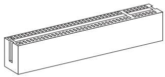
Memory
These DIMM slots are used for installing memory modules. For more information on compatible components, please visit http://www.msi.com/index.php?func=testreport
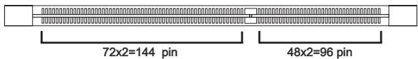
DDR3
240-pin, 1.5V
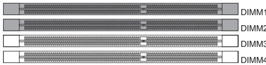
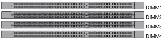
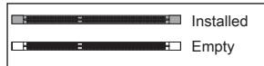
Dual-Channel mode Population Rule
In Dual-Channel mode, the memory modules can transmit and receive data with two data bus lines simultaneously. Enabling Dual-Channel mode can enhance the system performance. The following illustrations explain the population rules for Dual-Channel mode.


Important
- DDR3 memory modules are not interchangeable with DDR2 and the DDR3 standard is not backwards compatible. You should always install DDR3 memory modules in the DDR3 DIMM slots.
- In Dual-Channel mode, make sure that you install memory modules of the same type and density in different channel DIMM slots.
- To ensure a successful system boot-up, always insert the memory modules into the DIMM1 first.
- Due to the chipset resource deployment, the system density will only be detected up to 15+GB (not full 16GB) when each DIMM is installed with a 4GB memory module.
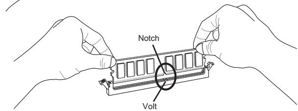
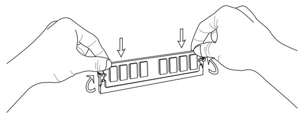
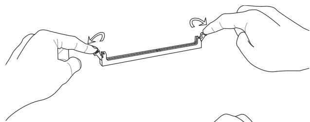
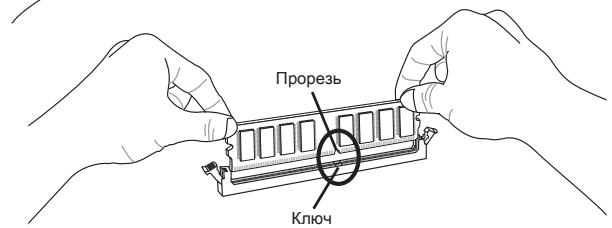
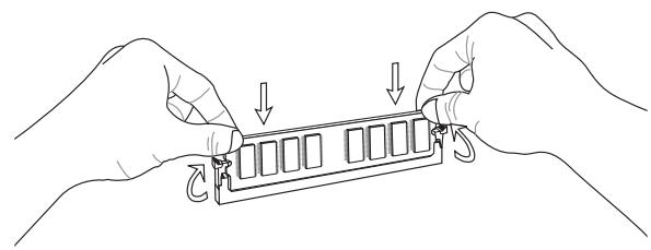
Installing Memory Modules
- The memory module has only one notch on the center and will only fit in the right orientation.
- Insert the memory module vertically into the DIMM slot. Then push it in until the golden finger on the memory module is deeply inserted in the DIMM slot. The plastic clip at each side of the DIMM slot will automatically close when the memory module is properly seated.
- Manually check if the memory module has been locked in place by the DIMM slot clips at the sides.

Important
You can barely see the golden finger if the memory module is properly inserted in the DIMM slot.
Power Supply
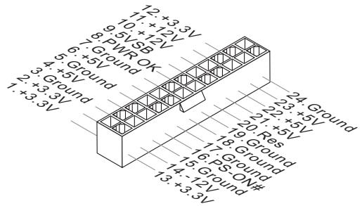
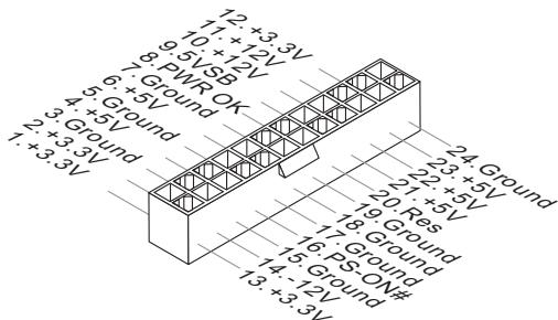
ATX 24-pin Power Connector: JPWR1
This connector allows you to connect an ATX 24-pin power supply. To connect the ATX 24-pin power supply, make sure the plug of the power supply is inserted in the proper orientation and the pins are aligned. Then push down the power supply firmly into the connector.
You may use the 20-pin ATX power supply as you like. If you'd like to use the 20-pin ATX power supply, please plug your power supply along with pin 1 & pin 13.
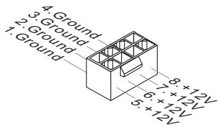
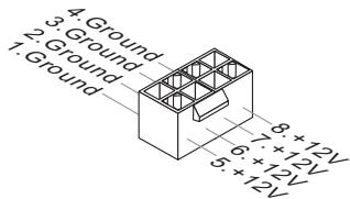
ATX 8-pin Power Connector: JPWR2
This connector provides 12V power output to the CPU.
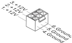
ATX 6-pin Power Connector: JPWR3
This connector is used to provide power to the graphics card.

Important
Make sure that all the connectors are connected to proper ATX power supplies to ensure stable operation of the mainboard.
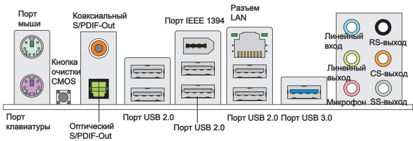
Back Panel
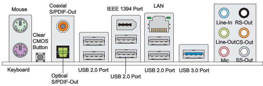
Mouse/Keyboard
The standard PS/2® mouse/keyboard DIN connector is for a PS/2® mouse/keyboard.
> Clear CMOS Button
There is a CMOS RAM on board with an external battery power supply to preserve the system configuration data. With the CMOS RAM, the system can automatically boot OS every time it is turned on. If you want to clear the system configuration, use the button to clear data. Press the button to clear the data.
Important
Make sure that you power off the system before clearing CMOS data.
After pressing this button to clear CMOS data in power off (G3) state, the system will boot automatically.
Coaxial S/PDIF-Out
This S/PDIF (Sony & Philips Digital Interconnect Format) connector is provided for digital audio transmission to external speakers through a coaxial cable.
Optical S/PDIF-Out
This S/PDIF (Sony & Philips Digital Interconnect Format) connector is provided for digital audio transmission to external speakers through an optical fiber cable.
USB 2.0 Port
The USB (Universal Serial Bus) port is for attaching USB devices such as keyboard, mouse, or other USB-compatible devices. Supports data transfer rate up to 480Mbit/s (Hi-Speed).
IEEE 1394 Port
The IEEE 1394 port on the back panel provides connection to IEEE 1394 devices.
USB 3.0 Port
USB 3.0 port is backward-compatible with USB 2.0 devices. It supports data transfer rate up to 5 Gbit/s (SuperSpeed).
Important
If you want to use a USB 3.0 device, you must use the USB 3.0 cable to connect to the USB 3.0 port.
LAN
The standard RJ-45 LAN jack is for connection to the Local Area Network (LAN). You can connect a network cable to it.

| LED | Color | LED State | Condition |
| Left | Yellow | Off | LAN link is not established. |
| On(Steady state) | LAN link is established. | ||
| On(brighter & pulsing) | The computer is communicating with another computer on the LAN. | ||
| Right | Green | Off | 10 Mbits/sec data rate is selected. |
| On | 100 Mbits/sec data rate is selected. | ||
| Orange | On | 1000 Mbits/sec data rate is selected. |
Audio Ports
These audio connectors are used for audio devices. It is easy to differentiate between audio effects according to the color of audio jacks.
- Line-In (Blue) - Line In, is used for external CD player, tape-player or other audio devices.
Line-Out (Green) - Line Out, is a connector for speakers or headphones. - Mic (Pink) - Mic, is a connector for microphones.
RS-Out (Black) - Rear-Surround Out in 4/5.1/7.1 channel mode.
CS-Out (Orange) - Center/ Subwoofer Out in 5.1/ 7.1 channel mode.
SS-Out (Gray) - Side-Surround Out 7.1 channel mode.
Connectors
Serial ATA Connector: SATA1~6
This connector is a high-speed Serial ATA interface port. Each connector can connect to one Serial ATA device.
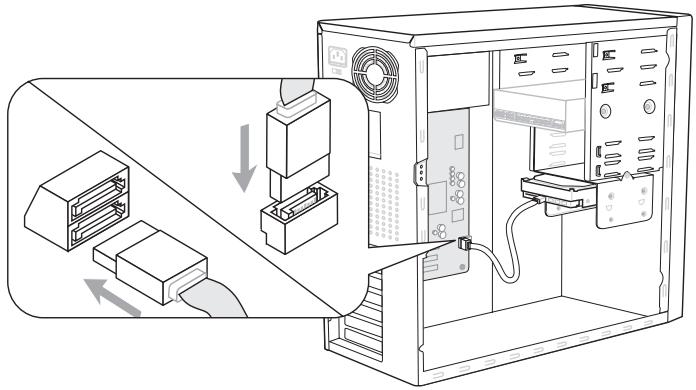
* The MB layout in this figure is for reference only.
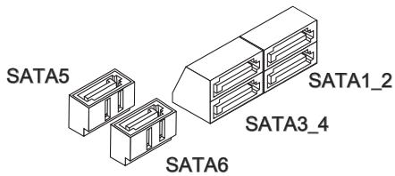
Important
Please do not fold the Serial ATA cable into a 90-degree angle. Otherwise, data loss may occur during transmission.
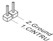
Chassis Intrusion Connector: JCI1
This connector connects to the chassis intrusion switch cable. If the chassis is opened, the chassis intrusion mechanism will be activated. The system will record this status and show a warning message on the screen. To clear the warning, you must enter the BIOS utility and clear the record.
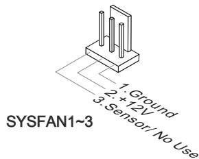
Fan Power Connectors: CPUFAN, SYSFAN1~3
The fan power connectors support system cooling fan with +12V . When connecting the wire to the connectors, always note that the red wire is the positive and should be connected to the +12V ; the black wire is Ground and should be connected to GND. If the mainboard has a System Hardware Monitor chipset on-board, you must use a specially designed fan with speed sensor to take advantage of the CPU fan control.
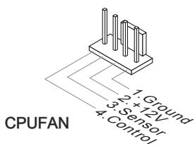
Important
- Please refer to the recommended CPU fans at processor's official website or consult the vendors for proper CPU cooling fan.
- CPUFAN supports fan control. You can install Control Center utility that will automatically control the CPU fan speed according to the actual CPU temperature.
- Fan cooler set with 3 or 4 pins power connector are both available for CPUFAN.
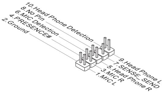
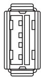
Front Panel Audio Connector: JAUD1
This connector allows you to connect the front panel audio and is compliant with Intel® Front Panel I/O Connectivity Design Guide.
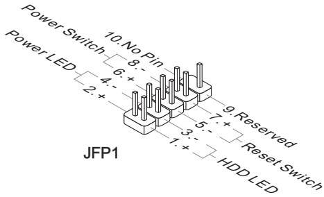
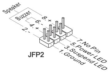
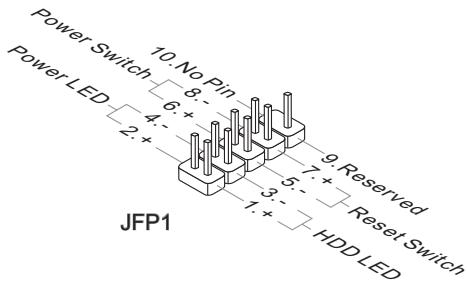
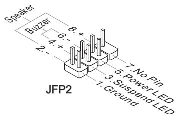
Front Panel Connectors: JFP1, JFP2
These connectors are for electrical connection to the front panel switches and LEDs. The JFP1 is compliant with Intel® Front Panel I/O Connectivity Design Guide.
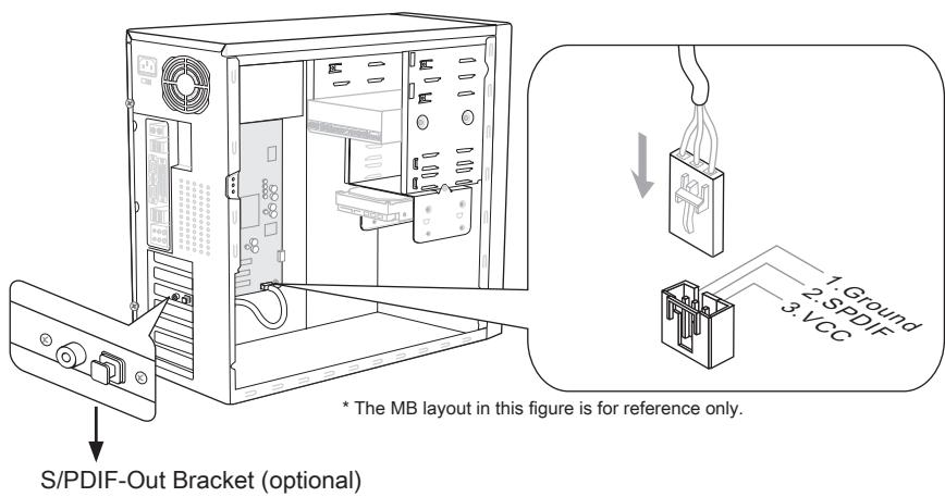
S/PDIF-Out Connector: JSP1
This connector is used to connect S/PDIF (Sony & Philips Digital Interconnect Format) interface for digital audio transmission.
Front USB Connector: JUSB1 / JUSB2 / JUSB3/ USB5
This connector, compliant with Intel® I/O Connectivity Design Guide, is ideal for connecting high-speed USB interface peripherals such as USB HDD, digital cameras, MP3 players, printers, modems and the like.
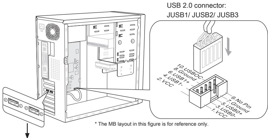
USB 2.0 Bracket (optional)
USB 3.0 connector: USB5
Important
- Note that the pins of VCC and GND must be connected correctly to avoid possible damage.
- If you want to use a USB 3.0 device, you must use the USB 3.0 cable to connect to the USB 3.0 port.
CD-In Connector: JCD1
This connector is provided for external audio input.
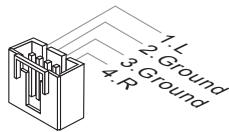
IEEE 1394 Connector: J1394_1
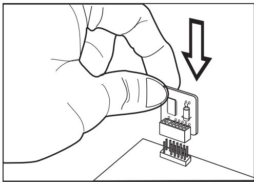
This connector allows you to connect the IEEE 1394 device via an optional IEEE1394 bracket.
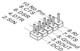
Serial Port Connector: JCOM1
This connector is a 16550A high speed communication port that sends/ receives 16 bytes FIFOs. You can attach a serial device.
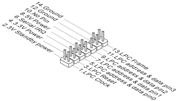
TPM Module connector: JTPM1
This connector connects to a TPM (Trusted Platform Module) module (optional). Please refer to the TPM security platform manual for more details and usages.
Jumper
Clear CMOS Jumper: JBAT1
There is a CMOS RAM on board with an external battery power supply to preserve the system configuration data. With the CMOS RAM, the system can automatically boot OS every time it is turned on. If you want to clear the system configuration, set the jumper to clear data.

JBAT1

Keep Data

Clear Data
Important
You can clear CMOS by shorting 2-3 pin while the system is off. Then return to 1-2 pin position. Avoid clearing the CMOS while the system is on; it will damage the mainboard.
Button
The mainboard provides the following buttons for you to set the computer's function. This section will explain how to change your mainboard's function through the use of button.
Power Button: POWER1
This button is used to turn-on or turn-off the system. Press the button to turn-on or turn-off the system.
Reset Button: RESET1
This button is used to reset the system. Press the button to reset the system.

GreenPower Button: GREEN1
This button is used to switch LED function of system. Once you press the button, the system will switch the LED between on and off mode.

OC Genie Button: OC Genie
This button is used to auto-overclock the system. When the system is in a power off state, pressing the button will enable OC Genie. The button will light up and lock into place. After booting up, the system will automatically detect the optimum values to overclock. To disable the OC Genie function, please press the button again after powering off the system. The button light will turn off, and the system will restore the default setting.

Important
- When using OC Genie, installation of DDR3 1333 and up memory and a better CPU cooler is highly recommended.
- We do not guarantee the OC Genie overclocking range and the damages or risks caused by the OC Genie overclocking behavior.
- You can disable the OC Genie function in BIOS setup. And we suggest you to save the OC Genie configuration to overclocking profile in BIOS for future using.
- The usage of OC Genie is at your own risk. Overclocking is never guaranteed by MSI.
Slots
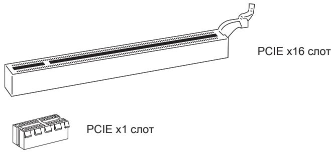
PCIE (Peripheral Component Interconnect Express) Slot
The PCIE slot supports the PCIE interface expansion card.

Important
When adding or removing expansion cards, make sure that you unplug the power supply first. Read the documentation for the expansion card to configure any necessary hardware or software settings for it, such as jumpers, switches or BIOS configuration.
PCI (Peripheral Component Interconnect) Slot
The PCI slot supports LAN card, SCSI card, USB card, and other add-on cards that comply with PCI specifications.
32-bit PCI Slot
Important
When adding or removing expansion cards, make sure that you unplug the power supply first. Read the documentation for the expansion card to configure any necessary hardware or software settings for it, such as jumpers, switches or BIOS configuration.
PCI Interrupt Request Routing
IRQ, or interrupt request line, are hardware lines over which devices can send interrupt signals to the microprocessor. The PCI IRQ pins are typically connected to the PCI bus pins as follows:
| Order1 | Order2 | Order3 | Order4 | |
| PCI Slot1 | INT E# | INT F# | INT G# | INT H# |
LED Status Indicators
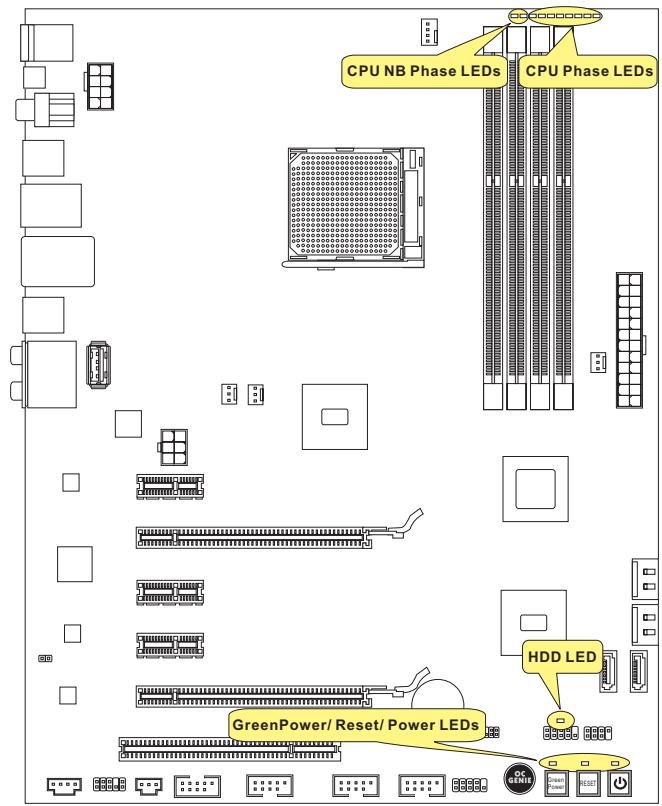
CPU NB Phase LEDs
These LEDs indicate the current CPU-NB power phase mode. Follow the instructions below to read.

Lights

Off
| □□ | CPU-NB is in 1 phase power mode. | ■■ | CPU-NB is in 2 phase power mode. |
CPU Phase LEDs
These LEDs indicate the current CPU power phase mode. Follow the instructions below to read.

Lights

Off
| CPU is in 2 phase power mode. | |
| CPU is in 4 phase power mode. | |
| CPU is in 6 phase power mode. | |
| CPU is in 8 phase power mode. |
Power LED
Every time you press the power button and it is functional, the power LED will blink once.
Reset LED
Every time you press the reset button and it is functional, the reset LED will blink once.
GreenPowerLED
Lights when you press the GreenPower button to switch the LED function of system on.
HDD LED
Lights when the hard drive is operating.
BIOS Setup
This chapter provides basic information on the BIOS Setup program and allows you to configure the system for optimum use. You may need to run the Setup program when:
- An error message appears on the screen during the system booting up, and requests you to run BIOS SETUP.
- You want to change the default settings for customized features.
Important
- The items under each BIOS category described in this chapter are under continuous update for better system performance. Therefore, the description may be slightly different from the latest BIOS and should be held for reference only.
- Upon boot-up, the 1st line appearing after the memory count is the BIOS version. It is usually in the format:
A7660AMS V1.X 061410 where:
1st digit refers to BIOS maker as A = AMI , W = AWARD , and P = PHOENIX . 2nd - 5th digit refers to the model number.
6th digit refers to the chipset as I = Intel, N = NVIDIA, A = AMD and V = VIA.
7th - 8th digit refers to the customer as MS = all standard customers.
V1.X refers to the BIOS version.
061410 refers to the date this BIOS was released.
Entering Setup
Power on the computer and the system will start POST (Power On Self Test) process. When the message below appears on the screen, press key to enter Setup.
Press DEL to enter SETUP
If the message disappears before you respond and you still wish to enter Setup, restart the system by turning it OFF and On or pressing the RESET button. You may also restart the system by simultaneously pressing
Getting Help
After entering the Setup menu, the first menu you will see is the Main Menu.
Main Menu
The main menu lists the setup functions you can make changes to. You can use the arrow keys (↑↓) to select the item. The on-line description of the highlighted setup function is displayed at the bottom of the screen.
Sub-Menu
If you find a right pointer symbol appears to the left of certain fields that means a submenu can be launched from this field. A sub-menu contains additional options for a field parameter. You can use arrow keys (↑↓) to highlight the field and press
General Help
The BIOS setup program provides a General Help screen. You can call up this screen from any menu by simply pressing <F1> . The Help screen lists the appropriate keys to use and the possible selections for the highlighted item. Press <Esc> to exit the Help screen.
The Main Menu
Once you enter BIOS CMOS Setup Utility, the Main Menu will appear on the screen. The Main Menu allows you to select from the setup functions and two exit choices. Use arrow keys to select among the items and press
Standard CMOS Features
Advanced BIOS Features
Integrated Peripherals
Power Management Setup
H/V Monitor
Green Power
BIOS Setting Password
Cell Menu
M-Flash
Overclocking Profile
Load Fail-Safe Defaults
Load Optimized Defaults
Save 8 Exit Setup
Exit Without Saving
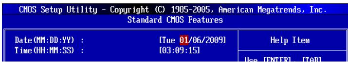
Standard CMOS Features
Use this menu for basic system configurations, such as time, date etc.
Advanced BIOS Features
Use this menu to setup the items of the BIOS special enhanced features.
Integrated Peripherals
Use this menu to specify your settings for integrated peripherals.
Power Management Setup
Use this menu to specify your settings for power management.
H/W Monitor
This entry shows your PC health status.
Green Power
Use this menu to specify the power phase.
BIOS Setting Password
Use this menu to set the password for BIOS.
Cell Menu
Use this menu to specify your settings for frequency/voltage control and overclocking.
M-Flash
Use this menu to read/ flash the BIOS from storage drive (FAT/ FAT32 format only).
Overclocking Profile
Use this menu to save/ load your settings to/ from CMOS for BIOS.
Load Fail-Safe Defaults
Use this menu to load the default values set by the BIOS vendor for stable system performance.
Load Optimized Defaults
Use this menu to load the default values set by the mainboard manufacturer specifically for optimal performance of the mainboard.
Save & Exit Setup
Save changes to CMOS and exit setup.
Exit Without Saving
Abandon all changes and exit setup.
When enter the BIOS Setup utility, follow the processes below for general use.
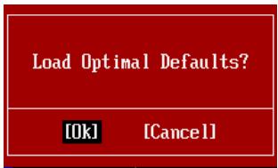
- Load Optimized Defaults: Use control keys ( ) to highlight the Load Optimized Defaults field and press < Enter>, a message as below appears:
Load Optimal Defaults?
[0k]
[Cancel]
Select [Ok] and press Enter to load the default settings for optimal system performance.
- Setup Date/ Time : Select the Standard CMOS Features and press
to enter the Standard CMOS Features-menu. Adjust the Date, Time fields.
- Save & Exit Setup: Use control keys ( ) to highlight the Save & Exit Setup field and press
, a message as below appears:

Select [Ok] and press Enter to save the configurations and exit BIOS Setup utility.
Important
The configuration above are for general use only. If you need the detailed settings of BIOS, please see the English manual on MSI website.
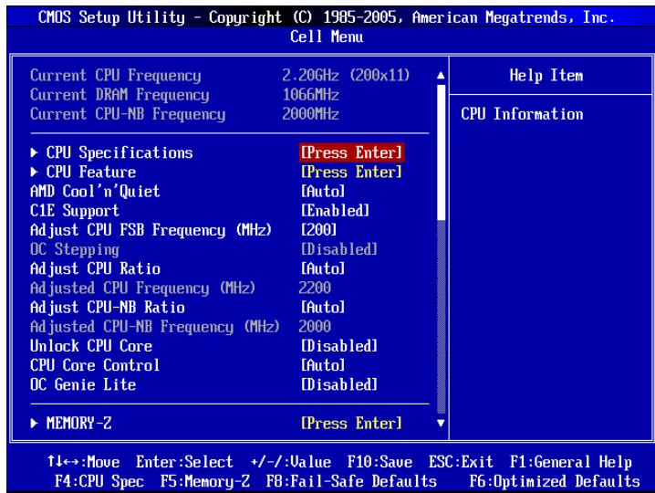
- Cell Menu Introduction : This menu is for advanced user who want to overclock the mainboard.
Important
Change these settings only if you are familiar with the chipset.
Current CPU / DRAM / CPU-NB Frequency
These items show the current clocks of CPU, Memory and CPU-NB speed. Read-only.
CPU Specifications
Press
CPU Technology Support
Press
CPU Feature
Press
AMD Cool'n'Quiet
The Cool'n'Quiet technology can effectively and dynamically lower CPU speed and power consumption.
Important
To ensure that Cool'n'Quiet function is activated and will be working properly, it is required to double confirm that:
-
Run BIOS Setup, and select Cell Menu. Under Cell Menu, find AMD Cool'n'Quiet, and set this item to "Enabled".
-
Enter Windows, and select [Start]->[Settings]->[Control Panel]->[Power Options]. Enter Power Options Properties tag, and select Minimal Power Management under Power schemes.
C1E Support
To enable this item to read the CPU power consumption while idle. Not all processors support Enhanced Halt state (C1E).
SVM Support
This item is used to enable/ disable SVM.
AMD Cool'n'Quiet
The Cool'n'Quiet technology can effectively and dynamically lower CPU speed and power consumption.
C1E Support
To enable this item to read the CPU power consumption while idle. Not all processors support Enhanced Halt state (C1E).
Adjust CPU FSB Frequency (MHz)
This item allows you to select the CPU Front Side Bus clock frequency (in MHz).
OC Stepping
This item will be enabled after you set the overclocking frequency in the "Adjust CPU FSB Frequency (MHz)". And the following items will appear. This items will help the system to overclock step by step after system booting up.
Start OC Stepping From (MHz)
This item is used to set the initial FSB clock. The system will boot with the initial FSB clock, and start to overclock from initial FSB clock to set FSB clock that you set in "Adjust CPU FSB Frequency (MHz)" step by step.
OC Step
This item is used to set how many steps for FSB colck overclocking.
OC Step Count Timer
This item is used to set the buffer time for every step.
Adjust CPU Ratio
This item is used to adjust CPU clock multiplier (ratio). It is available only when the processor supports this function.
Adjusted CPU Frequency (MHz)
It shows the adjusted CPU frequency. Read-only.
Adjust CPU-NB Ratio
This item is used to adjust CPU-NB ratio.
Adjusted CPU-NB Frequency (MHz)
It shows the adjusted CPU NB frequency. Read-only.
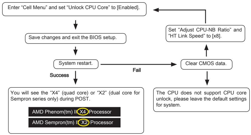
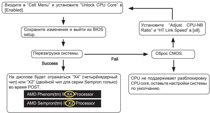
Unlock CPU Core
This item is used to unlock the CPU core. Please refer to the procedures below for CPU core unlocked in BIOS setup.
Important
CPU Core Control
- This CPU core unlocked behavior depends on the CPU ability/ characteristic, and it is not guaranteed.
- Depend on CPU's characteristic, once you get instable scenario, please restore the default settings for system.
- You can also check the core numbers in performance tab of Windows task manager.
This item allows you to select the number of active processor cores.
OC Genie Lite
Setting this item to [Enabled] allows the system to detect the maximum FSB clock and to overclock automatically. If overclocking fails to run, you can try the lower FSB clock for overclocking successfully.
MEMORY-Z
Press
DIMM1~4 Memory SPD Information
Press
Advance DRAM Configuration
Press
DRAM Timing Mode
This field has the capacity to automatically detect all of the DRAM timing.
1T/2TMemory Timing
This item controls the SDRAM command rate. Select [1T] makes SDRAM signal controller to run at 1T (T=clock cycles) rate. Selecting [2T] makes SDRAM signal controller run at 2T rate.
DCT Unganged Mode
This feature is used to Integrate two 64-bit DCTs into a 128-bit interface.
Bank Interleaving
Bank Interleaving is an important parameter for improving overclocking capability of memory. It allows system to access multiple banks simultaneously.
Power Down Enable
This is a memory power-saving technology. When the system does not access memory over a period of time, it will automatically reduce the memory power supply.
MemClk Tristate C3/ATLVID
This setting allows you to enable/disable the MemClk Tristating during C3 and ATLVID.
FSB/DRAM Ratio
This item allows you to select the ratio of FSB/ DRAM.
Adjusted DRAM Frequency (MHz)
It shows the adjusted Memory frequency. Read-only.
HT Link Control
Press
HT Incoming/Outgoing Link Width
These items allow you to set the Hyper-Transport Link width. Setting to [Auto], the system will detect the HT link width automatically.
HT Link Speed
This item allows you to set the Hyper-Transport Link speed. Setting to [Auto], the system will detect the HT link speed automatically.
Adjusted HT Link Frequency (MHz)
It shows the adjusted HT Link frequency. Read-only.
Adjust PCI-E Frequency (MHz)
This field allows you to select the PCIE frequency (in MHz).
Auto Disable DRAM/PCI Frequency
When set to [Enabled], the system will remove (turn off) clocks from empty DRAM/ PCI slots to minimize the electromagnetic interference (EMI).
- CPU VDD Voltage (V)/ CPU-NB VDD Voltage (V)/ CPU Voltage (V)/ CPU-NB Voltage (V)/ CPU PLL Voltage (V)/ CPU DDR-PHY Voltage (V)/ DRAM Voltage (V)/ DDR VTT Voltage (V)/ NB Voltage (V)/ NB PCI-E Voltage (V)/ SB Voltage (V)/ HT Link Voltage (V)
These items are used to adjust the voltage of CPU, Memory and chipset.
Spread Spectrum
When the mainboard's clock generator pulses, the extreme values (spikes) of the pulses create EMI (Electromagnetic Interference). The Spread Spectrum function reduces the EMI generated by modulating the pulses so that the spikes of the pulses are reduced to flatter curves.
Important
- If you do not have any EMI problem, leave the setting at [Disabled] for optimal system stability and performance. But if you are plagued by EMI, select the value of Spread Spectrum for EMI reduction.
- The greater the Spread Spectrum value is, the greater the EMI is reduced, and the system will become less stable. For the most suitable Spread Spectrum value, please consult your local EMI regulation.
- Remember to disable Spread Spectrum if you are overclocking because even a slight jitter can introduce a temporary boost in clock speed which may just cause your overclocked processor to lock up.
Software Information
Take out the Driver/Utility DVD that is included in the mainboard package, and place it into the DVD-ROM drive. The installation will auto-run, simply click the driver or utility and follow the pop-up screen to complete the installation. The Driver/Utility DVD contains the:
- Driver menu : The Driver menu shows the available drivers. Install the driver by your desire and to activate the device.
- Utility menu : The Utility menu shows the software applications that the mainboard supports.
Important
Please visit the MSI website to get the latest drivers and BIOS for better system performance.

Deutsch
870A Fuzion
Power Edition Serie
Spezifikationen
Prozessoren
Press DEL to enter SETUP
Advanced BIOS Features
Integrated Peripherals
Power Management Setup
H/V Monitor
Green Power
BIOS Setting Password
Cell Menu
M-Flash
Overclocking Profile
Load Fail-Safe Defaults
Load Optimized Defaults
Save 8 Exit Setup
Exit Without Saving
Integrated Peripherals
BIOS Setting Password
Overclocking Profile
Load Optimal Defaults?
[0k]
[Cancel]
Current CPU / DRAM / CPU-NB Frequency
Press
CPU Technology Support
Adjust CPU FSB Frequency (MHz)
Start OC Stepping From (MHz)
Adjusted CPU Frequency (MHz)
Adjusted CPU-NB Frequency (MHz)
Emplacement PCIE (Peripheral Component Interconnect Express)
Emplacement PCI (Peripheral Component Interconnect)
LEDs de phase CPU NB
Press DEL to enter SETUP
Standard CMOS Features
Advanced BIOS Features
Integrated Peripherals
Power Management Setup
H/V Monitor
Green Power
BIOS Setting Password
Cell Menu
M-Flash
Overclocking Profile
Load Fail-Safe Defaults
Load Optimized Defaults
Save 8 Exit Setup
Exit Without Saving
Standard CMOS Features (Fonctions CMOS standard)
Load Optimal Defaults?
[0k]
[Cancel]
CPU Technology Support
Adjust CPU FSB Frequency (MHz)
Start OC Stepping From (MHz)
HT Incoming/Outgoing Link Width
Pa3MeueHne KOMNoHEtOB CnCTeMHoI PJIaTbI
OTBepCTnIaKpeNJIeHnIa
Ipn yctaHOBKe cncTeHMHO nnTaBt HxKHO BCTaBnTb eB B KOpNc B npaBnJbHOM HanpaBnEHH. Pa3MeueHnra OTBepCtn dnn BnHTOB NOKa3aHb HnKe.
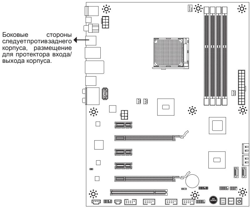
CneyuTe yka3aHnM BblIe yka3aHHo Iy TaHOBKn DepkaTeJIe B npabHbHom MeCTe B Kopnyce N 3atEm BBInHTnte BInTbI Chepe3 OTBepCTNJa Iy BInTOB B DePKaTeJI.
BhimhaHne
Bo n36eKaHne NOBpeKdEHH K CnCTeMHoI Pnate, IIObO KoTHaKT MeJy npOBoKamn CnCTeMHoI PnataI N KopnycOM UIN HeO6aTeIbHbI DePkaTeIb yCTaHOBJIeH B Kopnyce 3anpeuH.
- Y6eIntecb B TOM, UTO Ha CnCTeMHoN PIIaTe NII B KOpNyCe HET HNKaKOrO MetaJIINueCKORO KOMNoHEHTA, KOtOpBI MOKeT Bbl3BaTb 3aKOpaUvBaHne CnCTeMHoN PIIaTe.
CPU (LêntpaJbHbI npoceccop)
Pn yctaHOBKe CPU, uTo6bI y6peey npoecccop ot nepereBa, He 3a6yDbTe yCTaHOBt npoecccophny KJyep. EcnNy Bac HET npoecccopHoro KJyepa, nojkayncta, CBxKNTecb C dInepom C cIeblIO npio6peTeHn I erO yCTaHOBKn Do TORO, KaK BkIIOuHTe KOMNbHTep.
YcTaHOBKa MoDyJeI PAmrTn
- MoDyIi namrTn HmeHOT OndHy npope3b B cpeHneY cactN. MoDyIb BOJETB pa3beM ToIbKO pIpi IpaBnIbHOJ opHeNTaun.
- BCTaBbTe MoDyIb B DIMM cnot B BePtnKaJIbHOM HnPaBHeHN. 3aTeM HauKmTe Ha Hero, yTo6bl 30JOnueHbIe KOHTaKbTI rIy6Oko nOrpy3uInc b DIMM cnot. Ecnn MOyIb pAmrTn BCTaBNeH npaBnIbHO, To INaCTIKOBbIe 3aUeJIKN Ha o6oN X KOHcX 3akpoIOTc ABTomaTUnCeKN.
- BpyuHy u6eIITecb, yTo MoDyIb 3aKpePnIeB CcIote DIMM 3aUeIkamn c o6eHX CTOpOH.
BhimaHue
30JIOIe KOHTaKtbl eDBA BnHbI, ecNI MOyJIIN nAMrTI npAByIbHO pa3MeIeHbI B DIMM cnote.
Pa3bem NITaHn
24-KoHTaKTbI pa3bem nITaHnA TX: JPWR1
3TOT pa3bem NO3BOJnEET NOKlnHouNTb 24-KoHTaKTbI KOHKeTOp nITaHnA ATX. IJIra erO noKJIIOUeHnY b6eINTEcB, YTO KOHKeTOp N KOHTaKTbI pa3bema npabUNbHO copHeHTnpOBaHbI. 3aTeM nIoTHo BCTaBbTe erO B pa3bem Ha CnCTEmHO nIate.
BbI TAKKe MoKTe NcNoJIb3OBAtB 20-KoHTaKTHbIy ATX 6nok nTahn. PpN NcNoJIb3OBAHmN 20-KoHTaKTHOro pa3bema, NOdKJIuOaJte ero BDoJI KoHTaKToB 1 n 13.
8-KoHTaKThbI pa3bem nHTaHnA TX: JPWR2
3TOT pa3bem nHTaHn IcNoIb3yETcI dIg oEbcneHEnI nITaHn npOeccopa 12V.
6-KoHTaKTHbI pa3bem nITaHnA TX: JPWR3
3TOT pa3bem nITaHnI NCNoJIb3yETcI dIy o6eNeuHnI nITaHnI BInDeOkaTpbl.
BhIMaHHe
- Y6eINTecb B TOM,чTO BCE pa3bembl NOДКПоуЕbl K NICTOчнКam ПИТанЯ ATXдя CTa6NJIbHOH pa60Tb CnCTeMHo NIIaTbI.
3aHnaHeJIb
3TN KOHHeKTopbI NcNoJIb3yOTcI dIa NODKnIOUeHnI KHOJOK I INHdIKaTOpOB, paCNOJoxeHHbIX Ha nepeDneI naHEnI Kopnyca. KOHHeKTop JFP1 COOTBeTCTByet pykoBoIDCTBy Intel® Front Panel I/O Connectivity Design.
Pa3bem S/PDIF-Out: JSP1
KhoNka GreenPower: GREEN1
3Ta KhoNka NcNoJIb3YeTcI dIy BkIIOUeHnI/ BblKIIIOUeHnI cyHKuIN LED CnCTeMbI. Ipn Haxatm KhoNkCnCTema nepemHeJET cyHKuINoLED MeKdY BkIIOUeHnEM/ BBKJIIOUeHnEM.

Khonka OC Genie: OC Genie
3Ta KHONka IcNoIb3yETcI dIa ABtOMaTnueckoro pa3roHa cNCTeMb.I HaxMnte 3Ty KHOKNy dIra BKIOUeHnra FyHKuIN OC Genie, Korda cNCTema BbIKNUOeHa. Nocne HAXATNA KHOKNa FfKNCpYETcI b6yTe nOcBcYeHa. CNTema aBTOMaTnueCKN ONpeJENT ONITMaJIbHbIe 3NaHeHnRA pa3roHa nocNe 3arpy3Kn CNTeMb.I JIa BbIKNUOeHnra FyHKuIN OC Genie, HaxMnte 3Tu KHOKNy eIe pa3 nocNe BbIKNUOeHnRA cNCTeMb.I POnCBETKa KHOKN bIKNUOChTcR, IN cNCTema BOCCTaHOBnT npaMeTpbl NO yMOJUahNIIO.

BhimaHae
- Пи И спльзовани Функши OC Genie, Искрени pekomehdyeTc установы памгт b DDR3 1333 n Више, n установы луши вентлитор/ кулр дя устенов работыс Фунншим OC Genie.
- Mby He Moxem IpeDcKa3aTb BEnuHny pa3roHa OC Genie n He rapaHTnpyem OTCyTCTBnE BO3MOXhBix NOBpeKdEHH BBy3BaHHbIX NcNoIb3OBAHnEM OC Genie.
CyueCTByeT Bo3MOxHOCtB BbIKIIOHTb FyHKUHO OC Genie B HacTroKe BIOS. PekomeHdyetc coXpaHNTb KOHfNrgaPauuO OC Genie B BIOS dJa nCnOlb3oBaHnB 6byduem.
B3aTb Ha cBoi npCK 3a nCnoJIb3OBAHnE φyHKuN OC Genie. Pa3roH He rapaHTnpyeTcRA MSI.
CLOTbl
Cnot PCIE (Peripheral Component Interconnect Express)
Cnot PCIE noDpeXnBaet KapTb paacuHepnHa nHTepceca PCIE.
BhimaHne
Ipeud yctahOBko nnnn 3BneueHem Kapr pacuHpeHry ybeDntecb, yto Ka6ebnIITAHNn OTKnOyen OT 3NeKtpnuecko CETn. PpouTte DOKymeHTaCmHO Ha KapTy pacuHpeHry n BblONHnTe Heo6xOIMbIe annpaTHbIe nn nporpaMHbIe yCTAHOBKn Iy daHHo nn TaIbI, taKne kak NepembUKN, nepeKlnOuaTeI nn KOnHpyaCmIO BIOS.
Cnot PCI (Peripheral Component Interconnect)
Cnot PCI no3bONaIeYcTaHOBnTB KapTb LAN, SCSI, USB n dpyne DOnoNHTeBhIe KapTb paacupeHnA, KOtOpbIe COOTBeTCTByIOT cneunqkaun PCl.

32-bit PCI cnot
BHMHHE
Ipeed yctahOBko nIIN u3BneHHeM Kapr paUInepnHa ybeHtecb, YTO Ka6bIb IITaHNA OTKIOUeH ON 3NEKTPnuuecko CETN. PPOUTTE DOKyMeHTaCNIHO HA KapTy paUInepHn IN BbIOnHIne HeOxOIMbIe annapaTHBe NII pOrpaMhIE yCTAHOBKn IIN DaHHo IIaTbI, TAKNE KAP NepembyKN, NpeekNouateEN NIN KOHpypaCNIBOIS.
MapuTyI3aIyI 3aIpocOB npepbIbAHn PCI
IRQ - cokpaeeHne ot interrupt request (line) - linnna 3anpoca npepbBAHn, annapatna JINn, no KOTOpO yCTPoeCTBa MOryT nocblnTaB CnHAn npepbBAHn MKNpOpoeccopy. ObuHoe noKlnHoueHne PCI IRQ K KOHTaKTam LInHbPCI noka3aHo Hnke:
| Приказ1 | Приказ2 | Приказ3 | Приказ4 | |
| PCI сnot1 | INT E# | INT F# | INT G# | INT H# |
CBeTOBbIe HnDnKaTObpI

Индikatopь Фа3 CPU NB (CPU NB Phase LEDs)
3TN INDnKaTOpbl NOKa3bBAHOT peKIM pa60TbI nCTOuHnKa nITaHnCy CPU-NB. INDopMaunr O COCToRHN INDnKaTOpOB npNBedeHa B Ta6JIne.

BKJIIOUHEI

BbIKHQUEH
1a86kBa COOTBETCTByeT u3roTOBnTeIIO BIOS (A = AMI, W = AWARD n P = PHOENIX).
Cneyuoune 4 ucbpbcooTBcTcBbyOT Hmepy Moen.
Cnéýuǒaāyú KBa obo3hauaet nocTaBùnka yúnnceta (I = Intel, N = Nvidia, A = AMD, v V = VIA).
2 cneyuonhe 6kybbl o603naaioT 3ka3uKa MS = ctaHapTbn 3ka3uK.
V1.X COOTBETCTByeT Homepy BepCuN BIOS.
Press DEL to enter SETUP
(HaXmnte DEL nIy BxoJaB SETUP)
Ecni coo6eHHe nCye3I, a Bbl He ycneHn HaxaTb KnaBnUy, nepe3anyCTnte CnCTeMy, BbKlNoYB n ChOBA BKnIOuYB nITaHne, nn Haxab KhoNky RESET. MoXHo, TaKKe, nepe3anyCTntb CnCTeMy, Haxab OndHOBpeMeHHo KnaBnU
Pexim HactpoiK
BoiIaBpeXIMHactpoiKn, BbIcpa3y yBvIaNTe IlaBHOe MeHIO.
Main Menu (Главhoe мени)
Главhoe MeHIO coDEpXHT CnICOK HAcTpoE, KOTOpBIE Bbl MoKTe N3MeHNT.ДЯ BbIbopa moKHO nCNoJIb3OBAbT KJIaBNIu CO CTpeKNaMn (↑↓).CnpabKa O bblpaHHOH NaCTpoKe OTo6paKaaeTcB HnKHe YactN 3KpaHa.
Повменно
EcnBbObHApYKNTe,TO CnBea OT nyHKTa MeHIO NMeETc 3HaK npaBOr yka3aTeJRA 3To O3NaHaeT HaNInue NeODMeHIO, CoDEPKaUero DOnONHITeNbHbIe HAcTPOKN KOTOpBle MOxHcCdeJaTb B 3Tom NyHKTe. NcNoNb3yIte YnpabJIHOuNe KlaBnSi (↑ ↓) dIra BB6opa, a 3aTeM HaxMnte
POnpo6Na cnpaBka
B pexime hactpoikn BIOS nmeetc B03MOXHOCTb nonyehnna npdo6ho ncpaBKn. Ee moxho Bbl3BaT b3 JIO6O ro MeHIO npocTbIM HaxaTneM < F1> .B OKHe cnpaBKn 6ydt nepeuNCJIeHb BCE BO3MOXHbIe HactpoiKn B Bbl6paHHOM nyHKTe MeHIO.HaxmTe < Esc> dIra BblKJIUOeHnO kHa cnpaBKn.
The Main Menu (Главhoe мени)
Pn Bxode B pexkIM hactpoKIN BIOS Ha 3kpahe OTo6paxaetcra TnaBHOe MeHIO TnaBHOe MEHIO N03BOJRAET Bb6paTb FyHKmN HactpoKIN N IMeET Dba BapnaHTa BbIXoJa. IJI napeMeueHnI IO NyHKtAM NCNoJIb3yOTcR KNaBUnn CO cTepeKamN
Standard CMOS Features
Advanced BIOS Features
Integrated Peripherals
Power Management Setup
H/V Monitor
Green Power
BIOS Setting Password
Cell Menu
M-Flash
Overclocking Profile
Load Fail-Safe Defaults
Load Optimized Defaults
Save 8 Exit Setup
Exit Without Saving
Standard CMOS Features (CTaHdapTbHe yHKnm CMOS)
3To MeHIO N03BOJRAET yCTaHOBHTb OCHOBHbI NaPAMeTpbl KOHpNpyaCmN CnCTeMbI (daTy, Bpemr n T.I.).
Advanced BIOS Features (Дононтелови phukиni BIOS)
3To MeHIO NcNoB3yETcA DnI HAcTPOKn CneuaJIbHbIXΦyHKiN.
Integrated Peripherals (BcTpoEHbIe nepiFepriHbIe yctpoIcTa)
3To MeHIO NcNoJIb3yeTcra dIy HAcTpoiKn IapaMeTPOB BCTpoeHHbIX nepuΦepnHbIX yCTpoiCTB.
Power Management Setup (Hactpojka ynpablenia nntaHneM)
3To MEHIO NO3BOJAE T3aDaTb npaMeTpbl ynpabNeHnI NITaHHe mCTeMbI.
H/W Monitor (Montop annapathouactn)
3TOT nyHKT OTO6paKaAe COCTOaHHe annapaTHo Yactn PIK.
Green Power
3To MeHIO NcIOnb3yETcTdIpeKIMOB 3HePrc6epeKeHen.
BIOS Setting Password (Парол дocунka К hactpoикam BIOS)
3To MeHIO nCnOJIb3yETcA, YTO6bl 3aDaTb npoJIb.
Cell Menu (MeHIO y3Ja "Cell")
3To MeHIO NO3BOJARET ynpabJIaTb TaKTOBbIMu YactOTAMN HAnpJxKeHnMn npi pa3roHe CNTEmbl.
M-Flash
IcnoB3yETcA dIa YTeHn/ npoWNBKn BIOS c (B) BHeuHero HakOniTeTn (ToIbKO FAT/ FAT32).
Overclocking Profile
IcnoIb3yeTcI ypaHEnIy 3arpy3kn npaMeTpoB V/ n3 CMOS BIOS.
Load Fail-Safe Defaults
3To MeHIO nCnOJIb3yETcI dIa 3arpy3Kn 3HaueHNI BIOS, yCTaHOBJIeHHbIX npOn3BOIDntTeMe InIg CTaBnJbHOI pa60tbl CnCTeMbI.
Load Optimized Defaults (YcTaHOBnTb ONTmAmNbHbHe NaCTpoKn)
3To MeHIO NcNoJIb3yeTc DnI 3aRpy3KN HAcTpoEK N3rOToBnteJIg IJN ONTMaJIbHOI npOn3BOuNTeJIbHOCTn CnCTeMHoN PJIaTbI.
Save & Exit Setup (BbIXoI c coxaHeHem HacTpoEk)
3aIncb nImMeHenn B CMOS n BbIXoN n3 peXmHaHcTpoKn.
Exit Without Saving (BbIXoN 6e3 coxpanenHn)
OTMeHa BCex I3MeHEnI N BbIXoI n3 peKIma HAcTpoIKM.
B obsem cnyae, haxoJcB b pexKme HacTroKn BIOS, peKomeHdyetc BblOnHnTb cIeDyOuNe deICTBna.
- Load Optimized Defaults: KnaBnIaMn ynpaBJIeHnra ( ) BbIbepnte npHKT Load Optimized Defaults n haxmTe
, noBvTcS cIeDyUoee coo6uHne:
HaxmTe [Ok], 3aRpy3nTb HacrpoKn no yMOnuHaHIO dIra ONTMaJIbHO npOn3BOUnteJbHOCTN CNTeMbI.
He MeHryTe 3Tu HAcTPOiKN,ecNt BbI He 3HaKOMbl C OcObeHHoCTaMn TOHKoHAcTPOiKN YHNCETOB.
Current CPU / DRAM / CPU-NB Frequency
3Tn nyHkTBI noka3bBAIO T EkyuO yactOTy CPU u ckopocTb namrtn n CPU-NB. ToIbKO dIryTeHn.
CPU Specifications
HaxmTe
CPU Technology Support
Haxmte
CPU Feature
HaxmTe
AMD Cool'n'Quiet
TexHONorIa Cool'n'Quiet no3BOnJeT aΦΦeKTHBHO dInHAMnueckn n3MeHrTa cAcToTy CPU n 3nepronotpe6bene CnCTembl.
BHIMAHINE
Ytoby6eHntbCByTOM, YTO TexHOnIgna Cool'n'Quiet BkInoueHa npabotaet npabunbHo, Heo6xOdmo:
- 3aɪtn B npɒrρaʊmMy BIOS Setup, n BbɪbpaTb Cell Menu. Hauɪdnte AMD Cool'n'Quiet noD Cell Menu, n yctaHOBnTe erO B "Enabled".
- B Windows BBbepuTe [Start]->[Settings]->[Control Panel]->[Power Options]. BoiDte B Power Options Properties, BBbepuTe Minimal Power Management B Power schemes.
C1E Support
BkIouHte 3OT nyHKT IЯ cnKHeHn 3HeprOOnTp6neHn CPU, kOrda OH he pa6oTaET. He BCE npocecoppb noDdepxmbaOT Enhanced Halt state (C1E).
SVM Support
3TOT nyHKT nCnoJb3yETc dIy BkNIOeHn/ BbIKIOeHn SVM.
AMD Cool'n'Quiet
TexhONorra Cool'n'Quiet no3BOnJrE 3ΦΦeKTHBHO DnHaMnueckn N3MeHrTb YactOTy CPU n 3hepronotpe6neHne cnCTembl.
C1E Support
BkHouTe 3OT nyKt dIy cHIXeHn 3HepronoTpe6neHn CPU, KOrda OH He pa6oTaet. He BCE npoeccopbI noDepxNBAot Enhanced Halt state (C1E).
Adjust CPU FSB Frequency (MHz)
3TOT nyHKT no3BOJIAET bIbpaTb yactOry FSB npoceccopa (B MfU).
OC Stepping
3TOT nyHKT noRbIeTcnoCne yCTaHOBKn YacToTB pa3roHa B "Adjust CPU FSB Frequency (Mf). N noRbIeTc cneDyUoNnnyHKT. OH nO3BOJIeT ocUeCTBJIaTb pa3roH 1War 3a WAROM noCne 3aRpy3Kn CnCTeMbbl.
Start OC Stepping From (MHz)
3TOT nyHKT NO3BOJIeT yCTaHOBnTB hauaJIbHoe 3HaueHHe T aKTBOO qacTOtBI (FSB clock). CnCTema 3arpy3ntcra HauaJIbHbIM 3HaueHneM TaKTBOO qacTOtBI (FSB clock), a NOTOM hauHET pa3roHЯrTB cncTeMy c hauaJIbHOrO 3HaueHnIa 3a Iarom yCTaHOBJIeHHbIM B "Adjust CPU FSB Frequency (M_)
OC Step
TOT nyHKT nCOnb3yeTcI dIa 3aDaHnI WaIra pa3roHa TaKTOB YaCTOBy FSB.
OC Step Count Timer
TOT nyHKT nCNOJIb3yETc DnI yCTaHOBKn BpeMeHN 3aIepKkn KaKdOro Waara.
Adjust CPU Ratio
3TOT nyHKT nCnOJb3yETcI dIe pErynIpOBKm MHOxNTeI npOceccopa. OH DocTypeH ToIbKO TOrda, KOrDa npOceCCOP NOdEepXINBaET 3Ty dyHKUIO.
Adjusted CPU Frequency (MHz)
3TOT nyHKT nokazbIbaeTekyuO uactOtu CPU.ToIbKO dIy TcHn.
Adjust CPU-NB Ratio
3TOT nyHKT nCnoIb3yeTcIЯpeRyInpOBKu chaTOb CPU-NB.
Adjusted CPU-NB Frequency (MHz)
3TOT nyHKT noka3bBaet TekuHy uactOty CPU NB. TOnbKO dnyTeHnA.
Unlock CPU Core
ТOT nyнт Исплььчетдя pa36нокрвк CPU core. Следуту уka3аням Ниждя pa36нокрвк CPU core unlocked в насторke BIOS.
BhimaHue
-Данhoe DeиCTBne pa3bIOKIpOBKn CPU core 3aBucnt ot cnoc6hoctn/ xapaKTepcntIKOB CPU n He rapaHTnpyetc.
B 3aBncmocn OT xapaKTepeNtKOB CPU, KOrda nOraBJIeTc HecTa6bIbHa cnTyauZna, NOxAlyuCTa, BOCCTaHOBInTe HAcTpoKN CnCTeMbI No yMOJUHaHIO.
- Bam MÖXHÖ TAKKE npOBepuTB KOJIynchECTBO YIINCETOB B CTOnbSe BbICTpOeIcTBNe DInCnTepea3aayWindows.
CPU Core Control
3TOT nyHKT nCnoJIb3yETcA DnA BbIbopa KOnIYeCTBa AKTNBbIX npOceCCOpHbIX YInCeTOB.
OC Genie Lite
YctaHOBka 3TORO nyHKta B [Enabled] no3BOLJrE CnCTeMe ONpeJeTb MaKcIMaJIbHyIO yactOtY FSB n pa3roH aBtOMaTueckn. EcnPi pa3roH ne ydaIcra, Bam MOxHO yMeHbIHTb TAKTOByo YactOtY FSB dIra pa3roHa ydaIHO.
MEMORY-Z
Haxmnte
DIMM1~4 Memory SPD Information
Haxmte
Advance DRAM Configuration
HaxmTe
DRAM Timing Mode
3TOT nykT no3BOJAreT abTomatUeCKn OnpedJeTb BCE BpeMeHHbIe npametpbI DRAM.
1T/2TMemory Timing
3TOT nyHKT onpeJeIeET ckOpocb BbIaHcKOMaHd SDRAM. BbI6op [1T] npeBOoNT cnHaJIbHbIK KOHTpOJIeP SDRAM B pexIM pa60tby 1T (T=clock cycles).BbI6op [2T] npeBOoNT cnHaJIbHbIK KOHTpOJIeP SDRAM B pexIM pa60tby 2T.
DCT Unganged Mode
3TOT nyHKT nCnOJIb3yETcA dIa 06beDINHeHNA DByX 64-6nTHbIX DCT B ODNH 128-6nTHbI INTEPpeic.
Bank Interleaving
Bank Interleaving BJIaTc BaxKbIM npaMeTpom, BInraHouzim Ha npOn3BODiTteNbHocTb naMAYn. Ero BKIOUeHne N03BOJraT obpaatbc K HEckOJIbKM 6aHKam nAMrTn OndHOBpeMeHo.
Power Down Enable
3TOT nyHKT KOHTPOINPYET pa6O TY TEXHONORN 3HEPROC6epeXeHn. PpN OTCYCTBNN 6bpaueHn K pAMrTN B TeueHne HeKOTOPOro BpeMeHn, CNTema ABTOMATUeCKn yEmhShaet nTaHne dIy pAmrTN.
MemCik Tristate C3/ATLVID
3TOT nyHKT NO3BOJnE8 TBKJIOnuTaB/BbIKInOuaTb peKIM pa6Otbl C TpeMra COCTOHNMA BO BpemC3 n ATLVID.
FSB/DRAM Ratio
TOT nyHKt no3BONaTe perynipoBaTB qactOy FSB n DRAM.
Adjusted DRAM Frequency (MHz)
3TOT nyHKT nokaibAeT kcyuO yactOtynamrTo. TOnbKO dnyTeHn.
HT Link Control
Haxmnte
HT Incoming/Outgoing Link Width
3TOT nyHKT onpeJeIeT wipnHy BXoJaIe/NcXOJaIe IINH NTpn yCTaHOBKe B [Auto], cNCTema ABTomatUneCKn onpeJeIeT wipnHy WInHbI HT.
HT Link Speed
3TOT nyHKT noBONJET yCTaHOBnTB cKOpOCTb nepeaun no 7HHe HyperTransport. PnUyCTaHOBKe B [Auto], CNTema ABTomatueeCKn ONpeJeIET cKOpOCTb 7Hnbl HT.
Adjusted HT Link Frequency (MHz)
3TOT nyHKT nokaBbAeT TaKToByo YacToTy uINHbI HT. TOnbKO IaYteHnA.
Adjust PCI-E Frequency (MHz)
3TOT nyHKT NO3BOJAEYcTaHOBnTB yAcToTy PCIE (BMf).
Auto Disable DRAM/PCI Frequency
При установке 3наченя [Enabled], систema OTKПОЧИТ HeINСПОЛьзУЕмBLE pa3ьЕмbl namгту nPCI, чт по пиведдETК снчжению уровь злпektoramгнIHbIXnomex (EMI).
- CPU VDD Voltage (V)/ CPU-NB VDD Voltage (V)/ CPU Voltage (V)/ CPU-NB Voltage (V)/ CPU PLL Voltage (V)/ CPU DDR-PHY Voltage (V)/ DRAM Voltage (V)/ DDR VTT Voltage (V)/ NB Voltage (V)/ NB PCI-E Voltage (V)/ SB Voltage (V)/ HT Link Voltage (V)
Tn npKtbI no3BOJIAOT perynIpOBaTB napanjeHne CPU, naMaTn, nUnceta.
Spread Spectrum
Tak kak TakTOBbI rHeHApOp CnCTeMHoN IJIaTbI NmNyIbChbI, To erO paBOta BblBaet 3JeKTPomarHHTbIe nomexi - EMI (Electromagnetic Interference). ΦyHKuŋa Spread Spectrum cnHkaet 3tN nomexi, reHepnpy crJaXeHHble nMnyIbCbl.
BhimhaHue
- Ecnn y Bac Het npo6lne m nomexamn, ocTabte 3naeHne [Disabled] (3anpeueho) Дялушew CTabunbHOCTn n pOn3BOaNTenbHOCTn. Ondako, ecnn y Bac BO3NkaOT 3NeKTPomarHHTbIe nomexn, Bbl6epnte Spread Spectrum dny nx yMeNbSeHnry.
-ЧмбльшеЗачениSpread Spectrum,temнжсудетуровьлкгомагHTbIXnomex,HOcntema ctaHET Mehee ctabиь窝.Дявьбopa noxodzaero 3auehenia Spread Spectrum,Cbepbtecb co 3auehenmUyobHei 3eKtpomarHHTbIXnomex,yctahOBnEHbX 3akHOdaTeNbCTBOM. - He 3a6ydbTe 3anpeTntb uCnOJb3ObaHne yHKnUu Spread Spectrum, eCnn Bbl "pa3roHaeTe" CnCTeMHyO pNAty. 3To Heo6xOdmo, TaK KaK dAxe He6onbUoJ Dpe6e3r CnHaIOB TaKTOBOrO rHePApota MoKeT npIBeCTn K OTKa3y "pa3orHaHHoro" npouecoppa.
CBeHnO nporpaMMHom oecneueHH
YctahOBtBe B DVD npBOD nck Driver/Utility (DpaBebpb i yTuINtBi) n3 KOMnIeKta IOCTaBKn CnCTeMHo nnTaBi. ABToMaTneCKn 3anycTntcra IHCTaJIaIaIyra. HaxMtTe Ha HA3BaHne dpaiBepa/ yTuINtBi n cNeDuYte INHCTpyKzmaM ha 3kpaHe IJRA 3aBepSeHnI HCTaJIaIaIynn. Dnck Driver/Utility codepKHT:
- Driver menu (Ménhó dpaibépoB) - Ipejctabnietnepeyehb doctynbix dpaiéboB. YctahOBiTE dpaiébepbl nnoKJIoueHn Heo6xOIMbIX yCTPOIcTB.
- Utility menu (Meho yTnnt) - Poka3bBaet yTnntbl, KOTOpble noDepKnaOTc CNTeMHOn nlaToI.
BhimaHue
Ioxaynuicta, noceitte Be6caT MSI nna onnyeHn cambix HObIX dpaiBepOB IN BIOS, KOtOpblie no3BOJAT ynuuHT bpOn3BOUnteHbOCTb CNTeMbI.