
7CFT-NERO ISL - Basket FAGOR - Free user manual and instructions
Find the device manual for free 7CFT-NERO ISL FAGOR in PDF.
| Brand | FAGOR |
| Model | 7CFT-NERO ISL |
| Product type | Extracting / recirculating hood |
| Power supply | 220-240 V ~ 50/60 Hz (according to rating plate) |
| Suction power | 4 speeds + timed intensity (5 min) |
| Lighting | 2 halogen lamps 12 V / 20 W, type GU4 Ø35 |
| Grease filter | Metal, washable (hand or dishwasher), clean monthly |
| Activated charcoal filter | Rechargeable (recirculation version), cleanable every 2 months, replace every 3 years |
| Filter saturation indicator | Grease filter: 40 h – Charcoal filter: 160 h (resettable) |
| Special functions | Timer (1 to 20 min), clock, temperature alarm (>70°C), audible signal on/off |
| Installation type | Wall-mounted, telescopic chimney, external extraction or recirculation |
| Minimum cooking distance | 50 cm (electric) / 65 cm (gas or mixed) |
| Maintenance | Monthly external cleaning with damp cloth and neutral detergent – Do not use alcohol |
| Safety | Automatic shutdown in case of overheating, disconnect before maintenance, do not flambé under the hood |
| Weight | Approximately 15-20 kg (estimate) |
| Included accessories | Chimney, brackets, screws and wall plugs |
| Optional / not included accessories | Activated charcoal filter (if recirculation version), exhaust hose, clamps |
| Repairability | User-replaceable lamps; other parts: contact after-sales service |
| Warranty | Standard manufacturer warranty (check local conditions) |
Frequently Asked Questions - 7CFT-NERO ISL FAGOR
User questions about 7CFT-NERO ISL FAGOR
0 question about this device. Answer the ones you know or ask your own.
Ask a new question about this device
Download the instructions for your Basket in PDF format for free! Find your manual 7CFT-NERO ISL - FAGOR and take your electronic device back in hand. On this page are published all the documents necessary for the use of your device. 7CFT-NERO ISL by FAGOR.
USER MANUAL 7CFT-NERO ISL FAGOR
EN - Instruction on mounting and use
Consult the designs in the front pages referenced in the text by alphabet letters.
Closely follow the instructions set out in this manual. All responsibility, for any eventual inconveniences, damages or fires caused by not complying with the instructions in this manual, is declined.
Note: the elements marked with the symbol (^*) are optional accessories supplied only with some models or elements to purchase, not supplied.

Caution
WARNING! Do not connect the appliance to the mains until the installation is fully complete.
Before any cleaning or maintenance operation, disconnect the hood from the mains by removing the plug or disconnecting the home mains switch.
The appliance is not intended for use by children or persons with impaired physical, sensorial or mental faculties, or if lacking in experience or know-how, unless they are under supervision or have been trained in the use of the appliance by a person responsible for their safety.
Children should be monitored to ensure that they do not play with the appliance.
Never use the hood without effectively mounted grating!.
The hood must NEVER be used as a support surface unless specifically indicated.
The premises must be sufficiently ventilated, when the kitchen hood is used together with other gas combustion devices or other fuels.
The suctioned air must not be conveyed into a conduit used for the disposal of the fumes generated by appliances that combust gases or other fuels.
The flaming of foods beneath the hood itself is severely prohibited.
The use of exposed flames is detrimental to the filters and may cause a fire risk, and must therefore be avoided in all circumstances.
Any frying must be done with care in order to make sure that the oil does not overheat and burst into flames.
As regards the technical and safety measures to be adopted for fume discharging it is important to closely follow the relations provided by the competent authorities.
The hood must be regularly cleaned on both the inside and outside (AT LEAST ONCE A MONTH, it is in any event necessary to proceed in accordance with the maintenance instructions provided in this manual)..
Failure to follow the instructions as concerns hood and filter cleaning will lead to the risk of fires.
Do not use or leave the hood without the lamp correctly mounted because of the possible risk of electric shocks.
We decline any responsibility for any problems, damage or fires caused to the appliance as the result of the non-observation of the instructions included in this manual.
This appliance is marked according to the European directive 2002/96/EC on Waste Electrical and Electronic Equipment (WEEE). By ensuring this product is disposed of correctly, you
will help prevent potential negative consequences for the environment and human health, which could otherwise be caused by inappropriate waste handling of this product.

on the product, or on the documents product, indicates that this appliance may usehold waste. Instead it should be taken collection point for the recycling of electrical.
ment. Disposal must be carried out in
cal environmental regulations for waste
For more detailed information about treatment, recovery and recycling of this product, please contact your local council, your household waste disposal service or the shop where you purchased the product.
Use
The hood is designed to be used either for exhausting or filter version.
Ducting version
The hood is equipped with a top air outlet B for discharge of fumes to the outside (exhaust pipe and pipe fixing clamps not provided).
Attention!
If the hood is supplied with carbon filter, then it must be removed.
Filter version
Should it not be possible to discharge cooking fumes and vapour to the outside, the hood can be used in the filter version, fitting an activated carbon filter and the deflector F on the support (bracket) G, fumes and vapours are recycled through the top grille H by means of an exhaust pipe connected to the top air outlet B and the connection ring mounted on the deflector F (exhaust pipe and pipe fixing clamps not provided).
Attention!
If the hood is not supplied with carbon filter, then it must be ordered and mounted.
The models with no suction motor only operate in ducting mode, and must be connected to an external suction device (not supplied).
Installation
The minimum distance between the supporting surface for the cooking vessels on the hob and the lowest part of the range hood must be not less than 50cm from electric cookers and 65cm from gas or mixed cookers.
If the instructions for installation for the gas hob specify a greater distance, this must be adhered to.

Electrical connection
The mains power supply must correspond to the rating
indicated on the plate situated inside the hood. If provided with
a plug connect the hood to a socket in compliance with current regulations and positioned in an accessible area. If it not fitted with a plug (direct mains connection) or if the plug is not located in an accessible area apply a bi-polar switch in accordance with standards which assures the complete disconnection of the mains under conditions relating to overcurrent category III, in accordance with installation instructions.
Warning: Before re-connecting the hood circuit to the mains supply and checking the efficient function, always check that the mains cable is correctly assembled.
Mounting
Before beginning installation:
- Check that the product purchased is of a suitable size for the chosen installation area.
- To facilitate installation, remove the fat filters and the other parts allowed and described here, dismantle and mount it.
To remove see also the relative paragraphs.
- Remove the active carbon (*) filter/s if supplied (see also relative paragraph). This/these is/are to be mounted only if you want to use the hood in the filtering version.
- Check (for transport reasons) that there is no other supplied material inside the hood (e.g. packets with screws (), guarantees (), etc.), eventually removing them and keeping them.
- If possible, disconnect and move freestanding or slide-in range from cabinet opening to provide easier access to rear wall/ceiling. Otherwise put a thick, protective covering over countertop, cooktop or range to protect from damage and debris. Select a flat surface for assembling the unit. Cover that surface with a protective covering and place all canopy hood parts and hardware in it.
- Disconnect the hood during electrical connection, by turning the home mains switch off.
- In addition check whether near the installation area of the hood (in the area accessible also with the hood mounted) an electric socket is available and it is possible to connect a fumes discharge device to the outside (only suction version).
- Carry out all the masonry work necessary (e.g. installation of an electric socket and/or a hole for the passage of the discharge tube).
Expansion wall plugs are provided to secure the hood to most types of walls/ceilings. However, a qualified technician must verify suitability of the materials in accordance with the type of wall/ceiling. The wall/ceiling must be strong enough to take the weight of the hood. Do not tile, grout or silicone this appliance to the wall. Surface mounting only.
Installation wall model
Fig. 5
Disconnect the hood during electrical connection, by turning the home mains switch off.
Remove the grease filter/s and the carbon filter frame.
-
Rest the suction unit on a flat surface and thread the lower part of the hood onto it.
-
Make all the electrical connections between the two parts.
- Permanently fix the cooker hood to the suction group with the 6 screws.
- Using a pencil, draw a line on the wall, extending up to the ceiling, to mark the centre. This will facilitate installation.
- Rest the drilling template against the wall: the vertical centre line printed on the drilling template must correspond to the centre line drawn on the wall, and the bottom edge of the drilling template must correspond to the bottom edge of the hood.
- Place the lower support bracket on the perforation diagram making it coincide with the traced triangle, mark the two external holes and perforate. Remove the perforation diagram, insert two wall-dowels and fix the support bracket of the hood with two 5 × 45 ~mm screws.
- Hang the hood onto the lower bracket.
- Adjust the distance of the hood from the wall.
- Adjust the horizontal position of the hood.
- Using a pencil mark the cooker hood permanent drill hole inside the suction group (1 or 2 fixing points are necessary for permanent mounting).
- Remove the hood from the lower bracket.
- Drill at the point marked (Ø8mm).
- Insert 1 or 2 wall screw anchors according to requirement.
- Apply the flues support bracket, G to the wall adherent to the ceiling, use the flues support bracket as a perforation diagram (if present, the small slot on the support must coincide with the line drawn previously on the wall) and mark two holes with a pencil. Make the holes ( 8mm) , and insert 2 dowels.
- Fix the chimney support bracket to the wall using two 5 × 45 ~mm screws.
- Hook the hood onto the bottom bracket.
- Fix the hood into its final position on the wall (ABSOLUTELY ESSENTIAL).
- Connect a pipe (pipe and pipe clamps not provided, to be purchased separately) for discharge of fumes to the connection ring located over the suction motor unit. If the hood is to be used in ducting version, the other end of the pipe must be connected to a device expelling the fumes to the outside. If the hood is to be used in filter version, then fix the deflector F to the chimney support bracket G and connect the other extremity of the pipe to the connection ring placed on the deflector F.
- Connect the electricity.
- Apply the chimney stacks and fasten them at the top to the chimney support _u^G^a(20b) using 2 screws (20a)
- Connect the control panel to the electronic box of the hood.
- Slide the bottom section of the chimney down until it completely covers the suction unit and slots into the housing provided on top of the hood.
- Fix the lower section of the chimney with two screws. Remount the carbon filter frame and the fat/s filter/s and check the perfect functioning of the hood.
Description of the hood
Fig. 1
- Control panel
- Grease filter
- Grease filter release handle
- Halogen lamp
- Vapour catcher
- Telescopic chimney
- Air outlet (used for filter version only)
Operation
Use the high suction speed in cases of concentrated kitchen vapours. It is recommended that the cooker hood suction is switched on for 5 minutes prior to cooking and to leave in operation during cooking and for another 15 minutes approximately after terminating cooking.
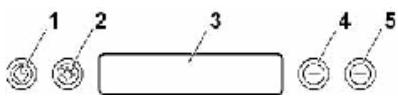
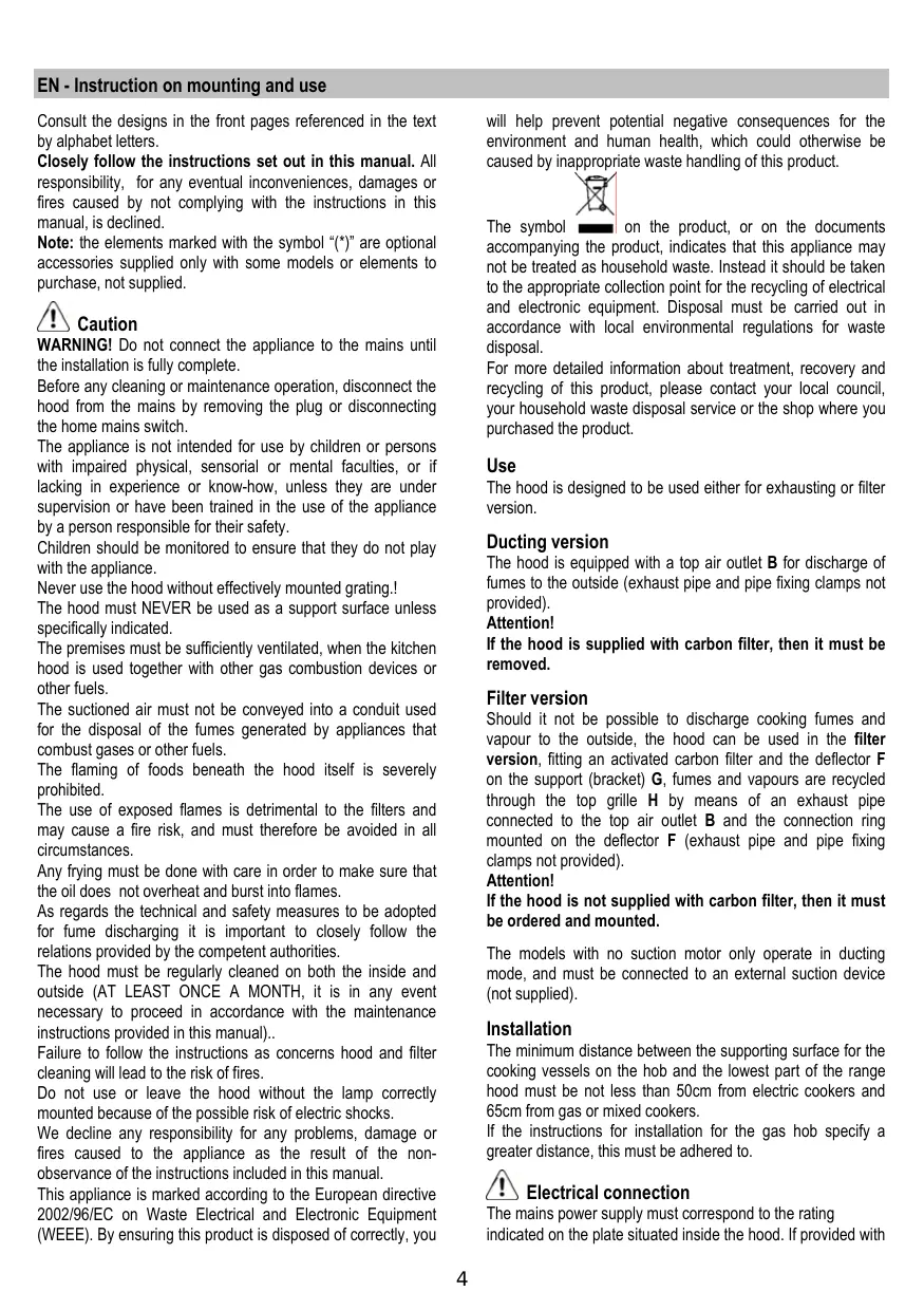
Control panel
- Timer button
The timer value can be increased or decreased in steps of 1 minute; the default time period is set to 10 minutes.
The value can be set to a time period of anywhere between 20 minutes and 1 minute.
Within 5 seconds of the "TIMER" button being pressed, the system will enter its programming mode and the user will be able to set the timer countdown period using the "-" and "+" buttons. If none of the buttons are pressed within a period of 5 seconds from when the Timer function was selected or the time period programmed, the countdown will begin.
The timer countdown can be activated as follows:
-
after pressing the TIMER button for the first time (default time value);
-
by pressing the TIMER button within 5 seconds of setting the desired countdown time period.
Once the timer has begun counting down, it may be cancelled by pressing the TIMER button.
- Light button
Light ON/OFF button.
- Display
Indicates the status of the hood.
- "Decrease motor speed / OFF button
The OFF status can be achieved by pressing the " - button and decreasing the motor speed until it stops.
- “+” Increase motor speed / ON button
The ON status can be achieved by pressing the "+" button; the motor will start at the lowest speed level.
The speed sequence is 1-2-3-4, therefore every time the "+" button is pressed the motor moves on to the next speed level.
If the motor is at the 4^th speed level and the "+" button is pressed, you will hear a beep.
The 4^th motor speed level is the intensive function and is timer-operated.
The standard period of time is 5^ , at the end of which the hood reverts to speed level 2.
To deactivate the function before the set time has elapsed, simply press the " - " button.
SPECIAL FUNCTIONS
Programming the Clock
The clock may be set at any time, apart from when the timer function is active.
The clock may be displayed in a 12-hour format, indicating a time between 1:00 and 12:59.
The clock may be reset by pressing and holding the "Timer" button for 5 seconds, then pressing the "-" and "+" buttons to adjust the time.
The user may increase/decrease the time in steps of 1 minute; however, if the "+" or "+" button is pressed for 1 second, the time is decreased/increased in steps of 5 minutes. In this case, the control panel rounds the time off to the nearest 5 minutes.
The user can end the clock resetting stage by pressing the "Timer" button.
If none of the buttons are pressed for 1 minute, the control panel accepts the set value and adds on 1 minute, then begins to operate normally.
Grease filter warning
After 40 hours of operation, "Grease Filter" appears on the display. When this text appears, the filter needs to be washed. To reset the grease filter warning, the user should press and hold the "+" button for 5 seconds. After this action, the "Grease Filter" text will disappear, a "beep" will be emitted to indicate the process is complete and the display will return to showing its normal operating functions.
The grease filter counter will reset after this procedure is complete.
Charcoal filter warning
After 160 hours of operation, "Charcoal Filter" appears on the display. When this text appears, the filter needs to be replaced.
To reset the charcoal filter warning, the user should press and hold the "." button for 5 seconds. After this action, the "Charcoal Filter" text will disappear, a "beep" will be emitted to indicate the process is complete and the display will return to showing its normal operating functions.
The charcoal filter counter will reset after this procedure is complete.
Enabling/disabling the charcoal filter warning
The charcoal filter may be enabled or disabled by pressing and holding the “-” and “+” buttons simultaneously for 5 seconds. The inclusion or exclusion
of the charcoal filter must be selected while the motor and light are OFF.
Charcoal filter excluded: the filter alarm is disabled.
Enabling/disabling the sound signal
The sound signals may be activated or deactivated by pressing and holding the "Light" button for 5 seconds.
If the sound signal has been activated, it should emit a beep and the text "Snd" should appear on the display for 2 seconds.
If the sound signal has been deactivated, the text "Snd" should appear on the display for 2 seconds and no beep should be emitted.
Temperature alarm
The hood is fitted with a temperature sensor which activates the motor at speed level 2 in the event that the temperature in the display area exceeds 70^ (the system monitors the data recorded by the sensor every 250 ms).
If the motor is OFF or at speed level 1 and the alarm intervenes, the motor will move to speed level 2 and the text "care" will appear on the display. While the appliance is in its alarm operating status, the user may only increase the motor speed (3^rd and 4^th levels). When the temperature of the cooker hood returns to a level below the alarm threshold, the motor will return to the status which was set before the alarm condition occurred.
3 minutes after the intervention of the alarm, the system will check the temperature in the display area again: if it is lower than 70^ , the operating conditions set prior to the intervention will be restored.
Maintenance
ATTENTION! Before performing any maintenance operation, isolate the hood from the electrical supply by switching off at the connector and removing the connector fuse.
Or if the appliance has been connected through a plug and socket, then the plug must be removed from the socket.
Cleaning
The cooker hood should be cleaned regularly (at least with the same frequency with which you carry out maintenance of the fat filters) internally and externally. Clean using the cloth dampened with neutral liquid detergent. Do not use abrasive products. DO NOT USE ALCOHOL!
WARNING:
Failure to carry out the basic cleaning recommendations of the cooker hood and replacement of the filters may cause fire risks.
Therefore, we recommend oserving these instructions.
The manufacturer declines all responsibility for any damage to the motor or any fire damage linked to inappropriate maintenance or failure to observe the above safety recommendations.
Grease filter
Fig. 2
This must be cleaned once a month (or when the filter saturation indication system - if envisaged on the model in possession - indicates this necessity) using non aggressive detergents, either by hand or in the dishwasher, which must be set to a low temperature and a short cycle.
When washed in a dishwasher, the grease filter may discolour slightly, but this does not affect its filtering capacity.
To remove the grease filter, pull the spring release handle.
Charcoal filter (filter version only)
Fig. 3
It absorbs unpleasant odours caused by cooking.
The charcoal filter can be washed once every two months (or when the filter saturation indication system - if envisaged on the model in possession - indicates this necessity) using hot water and a suitable detergent, or in a dishwasher at 65^ (if the dishwasher is used, select the full cycle function and leave dishes out).
Eliminate excess water without damaging the filter, then put it in the oven for 10 minutes at 100^ to dry completely.
Replace the mattress every 3 years and when the cloth is damaged.
Remove the filter holder frame by turning the knobs (g) 90^ that affix the chimney to the cooker hood.
Insert the pad (i) of activated carbon into the frame (h) and fit the whole back into its housing (j).
It is possible to use a traditional carbon filter, neither washable nor regenerable, to be replaced every 3 - 4 months.
The filter holder frame of the carbon filter is welded together; the eventual frame supplied with the hood is not, therefore, to be used.
Insert it into its housing and fix it turning the 2 plastic knobs.
Replacing lamps
Fig. 4
Disconnect the hood from the electricity.
Warning! Prior to touching the light bulbs ensure they are cooled down.
Use a small screwdriver as a lever on the borders of the lamp in order to remove the lightbulb.
- Slide out the lightbulb to be replaced and replace with a new 12V 20W 30^ Ø35 12V GU4.
- Carry out the replacement and mount the new lightbulb by following instructions in the reverse.
If the lights do not work, make sure that the lamps are fitted properly into their housings before you call for technical assistance.
Pred zahajenim instalace:
He octabte deTei be3 npncmToPa, UTO6bI OHn He irpaJIc np6opom.
He nCnoIb3yIte BbITaKky, ecIn peIeTka HnpaBnIbHO CMOHTnpoBaHa!
Kateropnueckn 3anpeuetaTcNIOJIb3OBAbBbITJkky KaueCTBe OONPHIPOCKoCTN,ecnI 3TO CNEuaJIbHO He OROBOpeHo.
Oe6ceyte HaIeKaun Bo3DyXoo6MeH NomeuHnA, KOrDa BbI cNoJIb3yIe BbITaKky B KyXHe OJHOBpeMeHHo C dpyrMn np6obapm Cra30bIM CkIgraHnEM nIi C pIITAHm EpyrMn ropUHMN.
BbITrMaBEmbBo3DyH DeOnJHe BbI6PcBaTbCn HApkyUepe3 Bo3DyXOBOD,NCIOJIb3yEmbIMnBbI6pOca DmOBOTnp6OpOB Cra30BbIM CxNtAHmE mNnC nHTaHmE dpYmMTopoUMM.
Kateropnueckn 3anpeaetcra roTOBn6bnoa "noi nIaMeHem, NOKoJIbky CBO6OdHoe IINAMr MOKeT NOBpeINb fNtTpbl n CTaTB npuHInOH noXapa; no3TOMy, BO3depKJBauTeCb ot 3TOR B LIO6om clyae.
KapenbB O bHbHom Macne DOnJxHO PpOn3BODnTbCnOIOCToHHbIM KOHTpoJIem, IMeB B Ndy, YTO nepeIpeTeoMACNo MoKET BOCIIaMeHrTBcR.
Yto kacaetc Texhuecknx Mep u ycIOBn no TexHnke 6e3oNaChOCTn npn OTBOe DbIMOB,TO npuIepKbAaTEcb cTporo npabIN, npdeymOTpeHHbIX peIamEHTOM MeCTHBIX KOMNETHTbIX BnacteY.
PpOIN3BOIDNTe NepNOIDNECKyO ONUCTky BbITJxKn KAc BHyTpn, TAK IN CHAPyKN (IO KPAIHEMPE PA3 B MECAL, BO BCYKOM CnUyae C COBnHOENEM yCIOBNI, KOtOpbIE CneuJaNbHO PnpEDyCMOTpeHb I HNCTpyKUHX NO 06cIyXBaHNIO daHnHO pyKOBoDCTBa).
HecobIHOeHHe IHCTpyKUINo ONUCTKe BbITaIKN I NO 3aMeHE N ONUCTKe FInbTPOB MOKET CTaTB PnUHNIO NOXAPA. He NcIOJIb3OBAt ININ OCTABNPTb BbITaIKy Be3 npAunIbHO yCTAHOBIIeHHbIX JAMIOueK BC8r3N C BO3MOxHBIM PNCKOM yDapa 3NeKTpUeCKM TOKOM.
Mblchimaem C c6eBCkyo OTBETCTBEHOCt 3a HeNoIaIKn, yuepe nnCropaHne pnpbopa BCNECTBne HecobJIOJeHHNCTpyKlni, pnpBeDeHHbIX B daHHom pyKOBOcTBe.
Данhoe Иделп epoMapKIpObaH BO COOTBETCTBn C Ebponeckoi DupeKTbOY 2002/96/EC no ytniHaCNI 3NeKTpUeCKoro I 3NeKTponHOrO obOpyobAnH (WEEE).
Oe6cnueH npaBnIbHyu yTnIIN3aIcNIO daHHoro n3dEJIa, BbI NOMOXETe PneDToBpAITb NOTEHuaIbHbIe HErATNBHeI NOcNEcTBnI DnI OKpyKaIOUeI cpebl I 3doPobBbYeIobEka, KOTOpBe MOrIN bI IMETb MECTO B IpOtnBHOM CNYae.

CnB01 Ha cAMOM n3dennn nIN cOpBoNDteHbHOJ DOKyMeHTaun yKa3bIAeT, YTO pRn yTnIIN3aUN daHHORO n3dennr C HMM HeN53 o6paauTcB KAK C obHybIMn 6bITobBMn OTxOnAMu BmecTo 3TOrO, erO cIeDyET cDaBaTb COOTBeCTByUoUnn pyNHKT npneMkn 3NeKtpueckoro n 3NeKTPOHNO O6OpyDoBAHnI dN NOcJIeDyUOeJ yTnIN3aUN.
CdaHa hCNOMdoJXHaIPOIN3BOIDHTCB8CAOOTBETCTBn C MEcTHbIMN PpABINAMN ITOYTNIN3aUN OTXoOB.
3a 6oJIe nOIOpObHOn INHΦOpMaJne O npABynax oBpaUeHncaTakIMN N3dJIINMn, INx yTNIIn3aUNn INpepeaBoTKnOBpaauaIteCB B MeCTHbE OprAHb IBaactN, B CnyKbNoyTNIIn3aUNn OTXoDOb INN B MaraINH, B KOTOpOM BInpnoBpeJIaDaHnoe IN3dJIe.
Пользоваиме
BbIyKa cKoHCTpyuPoBaHa dJa pa60Tb I B pexime OTbda BO3dYa hapyu Ky nPi nePcIpKUJIaun BO3dyxa.
IcnoHHeHc COTBOOM BO3Dyxa
BbIyKka Chabxeka BepxHMM BbIOHbIM OTBepCTnEM B DnIy Bbl6pOa DlMOB HapyKy (UcnoJIHeHne C OTBOOM BO3dyxa HapyKy - BbIOHaTpy6a N XOMYbTI KpeIIeHnHE BXoJrT B KOMIIKeT).
BHMaHne!
Ecnn BbITXkca Ch6KeHa yOrIbHbIM fNlbTpOM,To y6epnteero.
IcnoHHeHcOTbOdom Bo3dyxa
EcnIO TBIOB N napOB HApKy HeBO3MOKeH Bbl MOKeTe NOIbOaTcBc BITJAKKO B Peknme C peNPKyJIeuei npri NOMOuY rObnbIX QmIbTPOB N UCTAOBKn DEpNeKTopp F Ha KPOHIteH G. TaKIM O6pa30 OM uINeHHbIOT DlMOBbIX napOB Bo3DyX BO3BpaAaTcB N OMeUeHne Ypee3 BepxHIOpeWetky H bIBoNDHy Tpy6y, NOdCoeINHReMyK BepxHEmy BVIOBDHomY OTBePCTHy B, npri NOMOu CoeINHInTEbHOrOKoJIbCa, CMOnTIPOBaAHHOro HA DePNeKTope F (BbIOBNaTHpy6a n XOMyTbI KpENNEHnHE BxOJaT B KOMPiNeKT NoCTABKn).
BHMaHne!
Ecnn BbIyKa He Cha6XeHa yroJIbHbIM ΦnIbTpOM, To 3akaxnte n yctahOBnTe ero nepeid nCnOJIb3ObaHHem.
MoJeIN BbITJKeK 6e3 MOTOPHO 6JIoka MOrY pa6OtaTb B ODHOM peKIMe OTBDA BO3dYxa HApKy, NO3tOMy OHI DOnIKHbI 6bITb NIOCoEINHeHb K BHeUHei BbITJKHOH yCTAHOBke (HE BXODITB NOCTABKY).
YctaHObKa
PacctoHne HnKHeI rpaHbBITaXKnHaOnOpHn IIOCKOCTbIO NOcOcyDbHa XyKOHOI pNTe DOJXHO 6bITb He Mehee 50cm-ДЯ 3NeKtpuYeCKHX pINT,н He Mehee 65cm dIpyraObIX INI KOMbHINPOBaHHbx PINT.
EcnB INHCTpyKUxRn NO yCTaHOBe Ra3OBoI PJIITbI OROBOpeHo 6oJIbuee paCtOraHne,To yHTnte 3TO.

3Jektpnueckoe coeHneHne
Hnpanjxhene cTeI DOJNHO COOTBETCTBOBaTb HnpanjxhenIO, Yka3aHHOMy Ha Ta5nUHe TEXHNuecknx DaHbIX, KOtOpaa pa3MeuHa BHTpy np6Opa. Ecn BbITXkca Ch6xeha BInKo, NOKnOHTe ee K StENCeJIbHOMy pa3BeMy, OTEBuAIOeMy DeIcTBvUoMm npabINAM, KOtOpB IOJNXE6bItb paCNOxEH B IeKO DoCTynHom MeCTe. Ecn Jx BeBtXkHe Ch6xeha BInKo (DnI pRmoro NODKNOChEHNK CTeI), INI NSTcENbHLb pa3bEm He paCNOxEH BDOCTynHom MeCTe, TO NcNoJIb3yIte HADNeKaun DBxNOLIOCHb BYIKLIQUATEb, ObecneYBaIOUOn nONHoe pa3MbKAHHe CETn PnP BO3NHKHOBeHN yCNOBn NepehpanjxHenH 3-e KaterOpBN, COOTBETCTBN C NHCCTPyKlqMn No YCTAHOBKe.
BHIMAHHE: IpeXeIe Yem NIOKJIIOUHTb K CETn NITaHnA 3IeKTpUneCKyUO CNTeMBy BbITJAKN IN POBepNTb NCnPabHoe 4HyHKIIOHINPOBaHHe ee y6eIntecb B TOM, YTO Ka6eJIb NITaHnI PpaBnIbHO CMOHTPOBaH.
YctaHObKa
Пелед Началов могтаха:
- Поберы, Утобы размeperп побетенlorВами Иделя похонлін К ВьбранHomу мec'tу erо мontак.
Для obleneyehna MONTaKa peKOMeHnyem BpeMeHHO CHaTbФЛьТрbl-хИрОУнБЕТELI N DpyTne KOMПLEKTKUOJIne, CbEМ NOВТOPHA YCTaHOBka KOTOpbIX DOynyckaETcN OINCbIbAeTCB DAHHOM Tex. pYKOBODCTBE.
3TN KOMPNeKTyIOUe BOCCTaHaBJIbAHOCTc Ha CBOI MecTaNo 3aBepeHm MOHTaXKa BbITaKKn.
OnncHne npraIka Ix Cbema CMOTPe B COOTBeTCTByUOxNx pa3dEax.
CHMMTe yrOJIbHbI ΦINbTp/I,ecnOn OHmEHOCTc (CMOTPte TaKke COOBETCTBHyUo pa3dEn).ΦINbP/bI yctaHaBnBaIOCTc O6paTHO,ToJIbKO eCNi BbIXOTNE IcONJb3OBAtBbITJkkyBpeXIMPeZUPKyIaIzIM.
- Пюовьт, Утобы BHyTpN BByTЯЖи He ocTabaNoCb
прдmetов, NOMeUeHHbIx TyJa Ha BpEma ee
ТраHCNoptnIOBKN) (HaNpIMep, NaKetINKOB C uypynamM,
ПИСТКВ Гаран.Tи N.T.D.), eCIn OHN IMeHOTcR, BblHbTe IN
и COXpaHNTe.
- ПО ВЗМоЖнСТИ NGOTCeoДHINHTI NGOTCeoDINHTI NGOTCeoHINHTI NGOTCeoHINHTI NGOTCeoHINHTI NGOTCeoHINHTI NGOTCeoHINHTI NGOTCeoHINHTI NGOTCeoHINHTI NGOTCeoHINHTI NGOTCeoHINHTI NGOTCeoHINHTI NGOTCeoHINHTI NGOTCeoHINHTI NGOTCeoHINHTINGOTCeoHIN7I NGOTCeoHIN7I NGOTCeoHIN7I NGOTCeoHIN7I NGOTCeoHIN7I NGOTCeoHIN7I NGOTCeoHIN7I NGOTCeoHIN7I NGOTCeoHIN7I NGOTCeoHIN7I NGOTCeoHIN7I NGOTCeoHIN7I NGOTCeoHIN7I NGOTCeo HNNGTIOE NNTOeNTHIOE NNTOeNTHIOE NNTOeNTHIOE NNTOeNTHIOE NNTOeNTHIOE NNTOeNTHIOE NNTOeNTHIOE NNTOeNTHIOE NNTOeNTHIOE NNTOeNTHIOE NNTOeNTHIOE NNTOeNTHIOE NNTOeNTHIOE NCTOeNTHIOE NCTOeNTHIOE NCTOeNTHIOE NCTOeNTHIOE NCTOeNTHIOE NCTOeNTHIOE NCTOeNTHIOE NCTOeNTHIOE NCTOeNTHIOE NCTOeNTHIOE NCTOeNTHIOE NCTOeNTHIOE NCTOeNTHE DETAII.
Для подкючень ВITЯжки K cETN 3нeКТрОпТаниу OTКПIOЧITE habрахенье Ha obшем 3нeКТрИССКOM цinte Baшero DOMA. - Поберьтей такке, чебы ряdom с зони монтаяхы Витяжки (В 30нe, достунн Таске пол e монтаяхы Витяжки) Имелассеовая розетка и OTberрстпдядьIMOXODA, OTBOДЯшем Дьим на улuncу (Тольков В ржиме OTвODA).
BbIOnHnTe BCE Heo6xOuMbIe pa60TbI (HaPmEp: yctaHOBka cTeBOI PO3ETKN I/IIIN pOJeJIbIbAHne OTBepCTnI dIg DblMOxOHDn Tpy6bl).
BbITXkKa ChabkeHa IIO6JIaMn IIN KpEJIeHna ee B 6OBbnSInHCTBe CTEN/NOTOKOB. Ondako, Heo6xOJIMo 6obpatNTbCRA KBAIINuIcPiOBaHHOMy TEXHNY uSyebiTbcra TOM, YTO MaTePnAbl pNiroDHL nlaDaHORO TnNA cTeHb/ NOTOKA. CTeHa/NOTOKOL DOnKhbl ObNaadTaOHTOH npouHOCTbO C yETOM Maccbl pNbopa.
YcTaHOBKa MoeIIN DnA CTehBi
Pnc.5
OTcoeDInHtE BbITJkKy OT cETn, DeIcTBya Ha 03bl 3NeKTpUeCKOrO coeDInHeHa oBSeM 3NeKTpoUHTe.
CnHmnte fNtbp/bl 3aepKKn Knpa n depXaTeNb yroIbHoro fNtpa.
- YIOnKInTe BbITaRxoHoi 6IOK Ha IIOCKoe OCHOBaHne IM BCTaBbTe B Hero, CH3y, HNKHIOU cAcbb BbITaRKKn.
- BbInonJIHnTe 3eKtpnueckoe coeDInHeHne DByx cactei.
- 3aKpeHnTe OKOHnATEleBbHO BbITXkky K BbITXKHOMy 6Noey WypynMaN.
- KapaHdaWOM, HauepTne Ha CTHe Do nOTOnKa JINHIO, COOTBeTCTByUOyU OCEBoI JINHn YcTaHaBnBaEMo BbITAKK: 3TO OSeRHT ONepaUN No yCTaHOBKe.
5.ПисLOHITE W6bLOH K CTHe: cpeHnA BepTKaJIbHaN JINHn, HAneCEHnHa HA W6bLOH DOLJXHa COBnAaTb C OceBoH BepTKaJIbHOI JINHm, HaupeYehHo Ha CTHe; KpOme TORO, HNXnK KpOMKa W6bLOHa COOTBeCTByET HIXKHe TpaH NblTAAKKn. - Плоскто Нжхим onорь крштейн на за loн в COOTBETCTBm C 3aUHTPNXOBAHbIM ПямоуглнКOM, OTMeTbe ДBA BHEUHx OTBepctry nnpocBepnite IX, CHMITE WabLOH, BCTabte 2Дюбеля nЗakpenite onopbl kpoHteln noB bItrKky 2-My wypynam5x45 MM.
- HabeCbTe BbITaKky Ha HmKhHOIO cKo6y.
- Otperynnpyte pacctoHne BbIaKm OT cTeHbI
- Otperynpyte noIoxKeHne BbITaKKn IIO rnp3OHTaII
- N3HyTpN BbITrAHHoro 6Iboka, OTMeTbTe KapaHdaWOM OTBepCTne DnIgOKOHaTeJIbHorO KpeIIeHnB BbITrKKn (1 IIN2 MeCTa DnIgOKOHaTeJIbHorO KpeIIeHnA).
-
CHIMMTE BbITaKKy C HxKHeO KPOHHTeHa.
-
Ipo pa3MeTke npOeIaIte OTBepCTne (U8 MM).
- BCTaBbTe 1 nIin 2 dIO6eJI, KaK 3TO Heo6xOIMO.
14.3aKpeHnTe onOpHbI KPOHHTeH NOd KaMnHbI "G" KCTHe CmEXHO KNOTOKy; NcNOB3yTe OnpHbI KPOHHTeH NOd KaMnHbI B KAcTeB 7a60Ha (ecmno H0MeTcA, MAIOE OBaNbHOe OTBePCTNe B KPOHHTeH DEONKHO COOTBcTcBOBaTc C JINHE, paHee HaepYeHHo HA CTHe), OTMeTbTe KapaHaDawOM 2 OTBePCTn, npOdenaute OTBePCTn (XKMM), BCTABte 2 DIO6eJ. - 3akpenite onopbI KPOHTeH NOKAMNH KCTHe 2-My wypynm 5x45 MM.
- IOnDbecTe BbITaKK Ky KHNKHeMy KPOHHTeHy.
- 3akpenite OKOHaTeIbHo BbITraKy K CTeHe (HEINPEMEHHO HE05XODIMO!).
- Побевдente ВERTINЯЦИОнHyTOpy6у (tpy6a n XOMYtbl KpenPENHn He BXOJAT B KOMIJIeKT NocTbKN) K BYITJXHOI BTyJKe, paCNOJIOKHeHn Hnad 6IoKOM 3JIeKToDnBnIaTeJIa. Побевдente DpyroJ KOHeC Tpy6bI K CnCTeMe OTbOJa, B CInyae INCNoJIb3OBAHnN BByTJxKn BpeXnme OTBoJa DblMOH HApKy.
Ecnn BbXOTNE NcONb3OBaTb BbITaKbYBpeKIme peuPKyIaMn BO3dYaXa, 3akpeNITE deΦneKTOp F K KPOhUTeHny G nOJbEaNTe DpyToi KOHeu TpybI K CoeDINHTeBnHO BTyLKe, paCNOJoxEHHO Ha deΦneKTope F. - BbInonHnTe 3JIeKTPnueECKo NOkKnUoyHeHne.
- NocTabte KaMnHbI 3aKpeNITE IN 2-Mr Upyamn (20a) KOnOpHOMy KPOHHTeyHy G (20b).
21.Подсоевине панель управления к злестоною Коробк Витяжkin. - Onyctnte HnKHOIO ceKUIO KAMHnA (TeM cMbIM NOKpbIbAR NOHOCtBu BVITJXH0N 6NOK) n pa3MeCTnte ee B COOTBETCTBYOUEM THe3Ne HaB BVITJXKOi.
23.3aKpeNITe HxKHOIO CeKUIO KAMHa DByM RApyPnAmIyCTAHOBITE BHOBb DEPKaTeJIb yROJIbHOrO fIMlbTpA INfMbTp/bl 3aApEKPKNJIPA n PPOBepTe NcPpABHoeФyHKUHOHINPOBaHHe BVITAKKNI.
Onncnne BbTJxx
Pnc.1
- PanaHb ynpaBneHn
2.Фильтзадержк imma - Puyka otuenen HnФильтpa 3aedepeKn Knpa
- TanaoreHHaJ lamna
- OTKnDHOIeKpaH
- KamHH TeJIeCKOnIuYeCKn
- BbIOB Bo3dyxa (ToIbKO BpeKIMpeInpKyIaIIN)
Функуноваиме
Ib3yTeCb HTeHCMBbIM pexmOM pa60bI BbITgKKN B Cnyae oc6oB bICOKO KOHcHTpaUN KxOHhbIX nCnapeHNI. Mbl pekomEndyem BKJIOUHTb BbITgKkY 3a 5 MNHT do hauana npouceca npiroTOBJeHnPiUs N OCTaBtB ee BKIOUeHHoB TeueHne 15 MNHT npi6bn3ntEhNo n OKOHuaHN Ipouceca.
Kohconb ynpabJIeHnA
1. Khonka Taïmep
Hactpoika taImepa npOIm3BOJNTcY, yBEnuHbA rNIMyEmbHa Ha 1 MNHyTu fAbpnuHyo HactpoKy 10 MNHyT. POnlb3OBaTeJI MOKeT 3aAdTb 3NaHeHne O T 1 Do 20 MNHyT. POnCte HaxatnHa KOnIKN «TAYMEP» B TeChHe 5 ckynd CnCTema NepeKIOUaETcB PReKIM HAcTPOKn, N POnlb3OBaTeJI MOKeT 3aAdTb pNoDOnJXITeJIbHOCTb O6paTHOrO OTCeTa TaImepa pN iNoMOnUKN KHOJOK «-» I «+». EcIn B TeChHe 5 ckynd PocNe BbIbopaФynKUn Taimep He 6ydet BblOpHeNO HkAKnx HacTPOE KIN JNE O3aBePseHm HAcTPOKn HauNHaTcER O6paThB OTCeHT BPeMeHH TaImepa MoKeT 6bITb BKIOUeH CJeNyUoUIM O6pa3OM:
- Haxab Odnh pa3 KhoNky TAYMEP (pa6pnHna HacTpoiKa BpeMeHi);
- Haxkab KhoNky TAYMEP B TeueHne 5 cekynd nocJe HactpoKn HyxHoi npoJOnKnteJbHocTn o6paTHoro OTCeta.
Iocne hauana o6paTHo OTOcHeta TaMHepa OH MOKET 6bITb OTMeHEN pni NOMOUs KHOKN TAIMEP.
2. Khonka OcbeseHHa
Khoika BKJI./BbIKJI.ocBeueHnA.
3. DnCnJIeN
Poka3bIbaeTpeXIM BbITJAKK.
4. 一 KhONka yMeNbIeHnC kOpOCTn/BblKJI. dBnIaTeJIa
CnHann3aun 3acopenna HnIbtpa-KnpoyNoBtten
KaKdbIe 40 pa6oOx yacOB DnBraTeNHa dncPiNe noBnTcra Co6uHHe «Grease Filter» (FInbTpJxnpoyNoBtBe).Pp n oBnEHn Ha dcNPeee 3TOr coo6uHHe HEO6XoDmIO pOmbItb fNlbTp.
CnHnHaI3aIy yToIbHOrO fNtBtpa NcKlUoHe: npn erocatypaun CnHnHaI3aIy He BkIIOuAeTcR.
BknHoueHne/OTKnHoueHne 3ByKOBoCnHaHn3aun
3BykoBaa CnHaHnHaZaIg MoKet 6bITb BkHIOHeHa NII OTKHObHe, HaxBa KhoNky «Light» Ha 5 cekyHd.
Ecni 3ByKOBA CnHaJIIN3aCnB KInIOHeH, HbKInIOHaETcYMMep N Ha DnCnIe Ha 2 cekyHbI nOraBnIeTcCMBOI (Snd).
Ecπn 3bkyoBa CnHαnIa3aŋa OTKlUoyeHa, CmBON «Snd» nOaBlaTeCn Ha DnCnIee Ha 2 cekyHdbI, Ho 3ymMep He BKlIoUyaeTc.
CnHana3aunpeperpeBa
BbITXkka yKOMnNeKTObaHa TeMnepaTpHbIM DaTHNKOM, nepeKIOuAOUIM DIBrAteNB Ha 2-yo CKOpOCTb, eCNI TEMnePAtya B 30He DnCnIe NpBeBICNT 70^ (cNCTema KaKdIbe 250 McEK NOKa3bIbAE T3NaHeHne, N3MepeRoe daTHNKOB).
Ecnn DbrnateIb Bblknoch en npa6oTaet Ha 1-0iCKOcTNI, n BkHIOyaeTcraHnla3aunpeperpeBa,DbrnateIb nepeKIOyaeTcHa 2-yoCKOpocTb,aHa dnCnIee NOKa3bIAeTc coo6ueHne «care» (BHMAnHe).B coCTOHNn CnHnA3aunPiNb3OBaTeMb MoKeT TOnbKO yBeNCHtB ckOcTb DbrnateIa (Ha 3-bio nIu Ha 4-yoCKOpocTb).KOrDa TemnepaTpy BaITAKNN PONHIN3Tc HNKe nopora cpa6aTbIBAHNA CnHnA3aunpeperpeBa,DbrnateIb BEpHcTeB PexIM, PnpdeJeCTByUoUn CnHnA3aun. Ueep3 3MHytBu Nocle CpabaTbIBAHNA CnHnA3aunpeperpeBa CNCTMa BHOB pNoBepaET TempepaTyB 3OHe DNnPeJ: ecnn TEmpepaTpy HNKe 70^ , BItAKKa Bo3BpaauTcBA peKIM, peDSeCTByUoUn CnHnA3aun.
yxo
BHHMaHHe!IpeXeJeemBbINOnHtBJIIOyIO OTePaUHO NO YnCTKe Nnn TexHnueckOMy 06CnyKnBaHNO, OTOCoEHNHTe BbITJxKyOT 3JNEKTPocetN, OTOCoEHNRA BnKy nnn IraHBn BbIKNIOuATEb NOMEseHn.
OuInCTka
BbIyKka DoJIkHa NoDBeRpaTbCra YactOJ OChTKe KAc BHyTpN, TAK cHApYKn (No KpaIHe N Mepe C ToT Ke JepNOdHnOCTbIO, UTO n yXoD 3a FInbTpAmn DnI 3aDePekKn XnPa).ДЯ NcCTKn IcNcIb3yIte CneUmaIbHyO TpIky, CMOeHHyO HeIpaIbMbIm XmDkm MOIOUM CpeDCTBoM. He pIpmEHaTe CpeDCTBa, CdepKxAuIe abp3AINBHe MATEpMaIbI.
HE PIPMENHAYTE CINPT!
BHHMaHHe: He co6IIOJeHHe npaBnJ uCtKn npu6Opa n 3aMeHbI pInIbTPOB MOKeT npuBeCTN K pNcKy BO3HmKHOBeHn IooKapa. I03ToMy peKoMeHdyem co6JIIOaTb npuBeHnble HnCHtpkU.
CHNMAETCJIIO6aOTBETCTBEHHOCbB CBA3N C BO3MOXHbIMN IOBpeXdENHMn DBratateJN C NOKapAMN, BO3NHKShIMN BCNEcTBHe HnPaBnIbHOrPeMOHTa INH HeCO6JIIODeHNH BblSeONICAHbIX npdeUnpexdEnH.
ΦnIbTpbl3aIepJxKxJxpa
Pnc.2
Фильт сдуET 3aunuATb exeMeCeyH0 (Инл Korda cnCTema HnДКаUMn HacbIeEHNФиьТрOB, ecIn OHa ImeTcB BaWei MOnEIn, Yka3bIaEt Ha NaHHy Heo6xOdMocTb ) HearpeCCNBbIMMOUIMn CpeDCTBaMn, BpyHvIO INI B NocyDOMOeHNoH MaHne Prn Hn3KoTemNepaType N 3KOHOMMHOM LkNKeMbITb.
PmMbIbBe B NocyDOMOeHNO MaUNHe MOKET MeTb MeCTo HEKOTOPoe ObecuBcHuaBaHne FnIbTpA 3aJePckN Xnpa, Ho erO FnIbTpYUoAa XapakTepeNCTNa ocTaetc a6cONHO HEN3MeHHo.
- EN - Instruction on mounting and use
- Caution
- Use
- Ducting version
- Attention!
- Filter version
- Installation
- Electrical connection
- Mounting
- Before beginning installation:
- Installation wall model
- Fig. 5
- Description of the hood
- Operation
- SPECIAL FUNCTIONS
- Programming the Clock
- Grease filter warning
- Charcoal filter warning
- Enabling/disabling the charcoal filter warning
- Enabling/disabling the sound signal
- Temperature alarm
- Maintenance
- Cleaning
- WARNING:
- Grease filter
- Fig. 2
- Charcoal filter (filter version only)
- Fig. 3
- Replacing lamps
- Fig. 4
- Pred zahajenim instalace:
- Пользоваиме
- IcnoHHeHc COTBOOM BO3Dyxa
- BHMaHne!
- IcnoHHeHcOTbOdom Bo3dyxa
- YctaHObKa
- 3Jektpnueckoe coeHneHne
- YcTaHOBKa MoeIIN DnA CTehBi
- Pnc.5
- Onncnne BbTJxx
- Pnc.1
- Функуноваиме
- Kohconb ynpabJIeHnA
- Khonka Taïmep
- Khonka OcbeseHHa
- DnCnJIeN
- CnHann3aun 3acopenna HnIbtpa-KnpoyNoBtten
- BknHoueHne/OTKnHoueHne 3ByKOBoCnHaHn3aun
- CnHana3aunpeperpeBa
- yxo
- OuInCTka
- HE PIPMENHAYTE CINPT!
- ΦnIbTpbl3aIepJxKxJxpa
- Pnc.2
Brand : FAGOR
Model : 7CFT-NERO ISL
Category : Basket