
MN10CESWW - Air conditioner HONEYWELL - Free user manual and instructions
Find the device manual for free MN10CESWW HONEYWELL in PDF.


| Product type | Monoblock portable air conditioner |
| Brand | Honeywell |
| Model | MN10CESWW |
| Cooling capacity | 10,000 BTU/h (2.9 kW) |
| Recommended area | Up to 25 m² |
| Functions | Cooling, dehumidification, ventilation, night mode |
| Dehumidification | Up to 1.5 L/h |
| Airflow | 350 m³/h |
| Noise level | 52 dB (A) low mode, 56 dB (A) high mode |
| Dimensions (W x D x H) | 40 x 33 x 68 cm |
| Weight | 25 kg |
| Power supply | 220-240 V ~ 50 Hz, 10 A |
| Power consumption | 950 W (cooling) |
| Energy class | A |
| Refrigerant | R32, charge 300 g |
| Water tank | Auto-evaporation, manual drain in case of high humidity |
| Filter | Washable, dust pre-filter |
| Remote control | Yes, included |
| Timer | 24-hour programmable |
| Maintenance and cleaning | Clean the filter every 2 weeks, clean the condenser once a year |
| Safety | Frost protection, automatic shut-off in case of overheating |
| Spare parts and repairability | Filter available, remote control, exhaust kit (online repair manual) |
Frequently Asked Questions - MN10CESWW HONEYWELL
User questions about MN10CESWW HONEYWELL
0 question about this device. Answer the ones you know or ask your own.
Ask a new question about this device
Download the instructions for your Air conditioner in PDF format for free! Find your manual MN10CESWW - HONEYWELL and take your electronic device back in hand. On this page are published all the documents necessary for the use of your device. MN10CESWW by HONEYWELL.
USER MANUAL MN10CESWW HONEYWELL
EN Local Air Conditioner
User Manual
Read and save these instructions before use
FR Climatiseur Local
Mode d'emploi
natural_image
Line drawing of a Suneywell air purifier (no text or symbols on the device body)SE Lokal Luftkonditionering


www.honeywellportableac.com
info@honeywellportableac.com
READ AND SAVE THESE INSTRUCTIONS
IMPORTANT SAFETY INSTRUCTIONS. READ CAREFULLY AND KEEP FOR FUTURE REFERENCE. IN CASE THERE IS ANY INCONSISTENCY OR CONFLICT BETWEEN THE ENGLISH VERSION AND ANY OTHER LANGUAGE VERSION OF THE CONTENT OF THIS MATERIAL, THE ENGLISH VERSION SHALL PREVAIL.
WARNING:
- DO NOT operate the unit with a damaged plug or loose wall outlet. If the supply cord is damaged, it must be replaced by the manufacturer, its service agent or similarly qualified persons in order to avoid a hazard.
- DO NOT cover the air intake and exhaust when in use.
• DO NOT place objects on or sit on the unit. - Always turn off and unplug the unit when cleaning or servicing.
• DO NOT use the appliance if it is damaged. - If service is needed contact an authorized service agent.
- Unplug the unit when stored or not in use.
- DO NOT pull or carry the appliance by the power cord.
- DO NOT pinch the wire in the door and DO NOT pull it along edges or sharp corners.
- DO NOT run the power cord under carpeting and rugs.
- Use caution to prevent tripping on cord.
- DO NOT use the device in the following cases:
- Near a fire source
- In areas where gasoline, paint or other flammable goods are stored
- In an area where the water can be projected
- DO NOT touch the plug or the device with wet hands.
-
Basic safety precautions should always be followed when using electrical appliances.
-
This appliance has been manufactured for use in domestic environments and should not be used for other purposes.
- Only use the installation kit provided to install this unit. DO NOT attempt to extend the exhaust hose or install this unit using other methods other than that shown in this manual. Improper installation will void any existing warranties.
- DO NOT use an extension cord with this unit.
- This appliance can be used by children aged from 8 years and above, and persons with reduced physical, sensory or mental capabilities or lack of experience and knowledge if they have been given supervision or instruction concerning use of the appliance in a safe way and understand the hazards involved. Children shall not play with the appliance. Cleaning and user maintenance shall not be made by children without supervision.
- Never insert your fingers or rods into the air outlet. Take special care to warn children of these dangers.
- The manufacturer is not liable for injury caused to persons or property damage due to non-compliance with maintenance instructions and improper use of the appliance.
- The appliance shall be installed in accordance with national wiring regulations.
- The appliance is not to be used by persons (including children) with reduced physical, sensory or mental capabilities, or lack of experience and knowledge, unless they have been given supervision or instruction.
- Children should be supervised to ensure that they do not play with the appliance.
| SYMBOL NOTE EXPLANATION | ||
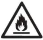 | WARNING | This symbol shows that this appliance uses a flammable refrigerant. If the refrigerant is leaked and exposed to an external ignition source, there is a risk of fire. |
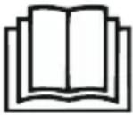 | CAUTION | This symbol shows that the operation manual should be read carefully. |
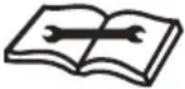 | CAUTION | This symbol shows that a service personnel should be handling this equipment with reference to the installation manual. |
 | CAUTION | This symbol shows that information is available such as the operating manual or installation manual. |
Additional warnings for appliances with R290 refrigerant gas.
- Read the instruction carefully before using the appliance.
• R290 refrigerant gas complies with European environmental directives. - This appliance contains a certain number of grams (see rating label at the back of the unit) of R290 refrigerant gas. The maximum refrigerant charge amount is 0.3 kg.
- When defrosting or cleaning, do not use any method other than those recommended by the manufacturer.
- Do not place the appliance in a room with continuous sources of ignition (e.g. open flame, operating gas appliance or working electrical heater).
- Do not pierce and do not burn.
- Do not perforate any part of the refrigerant circuit.
• Refrigerant gas may be odorless. - The appliance must be installed, used and stored in an area that is greater than 15m^2 .
- Accumulation of possible refrigerant leaks in an unventilated room could lead to fire or explosion should the refrigerant come in contact with electric heaters, stoves or other sources of ignition.
- The appliance must be stored in a way to prevent mechanical damage.
- Only individuals authorized by an accredited organization certifying their competence to handle refrigerants in compliance with industry legislation should work on the refrigerant circuit.
• Repair must be performed based on the recommendations from the manufacturer. - Maintenance and repair that requires the assistance of other qualified personnel must be performed under the supervision of specialists in the use of flammable refrigerants.
Congratulations on your purchase of this Honeywell Local Air Conditioner.
Regarding the information pertaining to the installation, handling, servicing, cleaning and disposal of the appliance, please refer to the below paragraph of the manual.
USER TIPS
Local Air Conditioners are ideal for spot cooling. The compressor, condenser and evaporator are housed in a compact unit. The air is dehumidified and cooled while a flexible exhaust hose sends heat outside. The air conditioner includes a window venting kit.
No permanent installation is needed. The unit is easy to move from room to room and offers a truly flexible air conditioning solution.
Auto Evaporation System - The unit automatically evaporates the condensate through the exhaust hose. There is no need to empty the drainage tank except in very humid conditions. Read and follow the instructions carefully.
To ensure optimal efficiency of the product, keep doors and windows closed when it is used as an air conditioner or dehumidifier. If the product is being used with the fan function only, an open window could improve air circulation.

natural_image
Simple line drawing of a server room with a window and four windows (no text or symbols)Cooling, Heating* and Dehumidifying Operation

natural_image
Simple line drawing of a server unit with a door symbol above it (no text or labels)Fan Operation
Important:
Before installing the unit, place it UPRIGHT for 1 hour before use to allow the refrigerant to stabilize. Manually adjust the air vent located at the top of the unit to adjust the direction of air flow.
- Follow installation instructions to set up the unit.
- Plug the unit into a properly grounded circuit. DO NOT plug into an extension cord.
*Applicable for models with Heating feature only.


1) Control Panel (Incl. Signal Receptor)
9) Remote Control
2) Air Outlet 10) Lower Drain Plug with Plastic Cap
(Air Conditioning Mode)
3) Handle 11) Upper Drain Plug
(Dehumidifier Mode)
4) Casters 12) Lower Dust Filter
5) Upper Dust Filter 13) Lower Grill
6) Upper Grill
7) Exhaust Hose Connector
8) Power Supply Cord
It is important that the installation instructions below are followed for successful installation of this Local Air Conditioner. Please call Customer Support if you have any difficulties or queries regarding these installation procedures.
①

natural_image
Simple line drawing of two connected circles with a connecting rod, labeled 'x1' at the bottom (no text or symbols on the circles)②

x1 x1
③
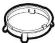
4
natural_image
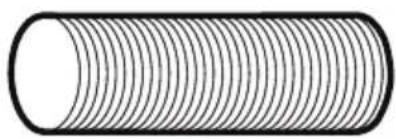
Pure diagram of a cylindrical object with evenly spaced radial lines, no text or symbols present.x1
5

x1
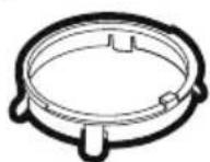
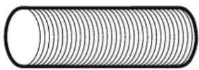
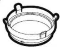
Installation Kit:
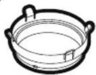
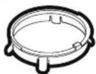
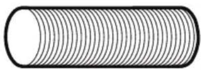
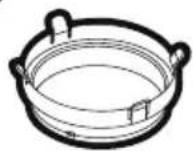
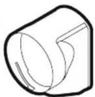
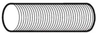
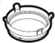
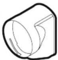
- Flange Fixture + Hole Cover (1 Piece) 4. Exhaust Hose (1 Piece)
- Exhaust Nozzle Adapter (1 Piece) 5. Exhaust Nozzle (1 Piece)
- Exhaust Hose Connector (1 Piece)
Installation Steps:
Through an Open Window
- Connect the Exhaust Nozzle Adaptor to the Exhaust Hose. Connect the Exhaust Hose Connector to the Exhaust Hose. Ensure proper fit on both ends. (See Fig. 1).
- Install the Exhaust Nozzle to the Exhaust Nozzle Connector. (See Fig. 2).
Fig.1 Fig.2

flowchart
graph LR
    A[" "] --> B[" "]
    B --> C[" "]
    C --> D[" "]
    D --> E[" "]
    style A fill:#f9f,stroke:#333
    style B fill:#ccf,stroke:#333
    style C fill:#cfc,stroke:#333
    style D fill:#fcc,stroke:#333
    style E fill:#cff,stroke:#333
INSTALLATION (CONTINUED)
- Connect the exhaust hose to the rear exhaust outlet on the back of the unit. Slide-in the exhaust hose connector downwards until it is locked in place.

natural_image
Line drawing of a portable air conditioner unit with a coiled hose inserted into the chamber (no text or symbols)Exhaust Hose:
Dia. 15cm (5.9")
Length: 30cm to 120cm (12" to 47")
- Extend the exhaust hose through an open window and close the window as far as possible trapping the Exhaust Nozzle (as shown below).

natural_image
Line drawing of a portable air conditioner unit with a coiled hose inserted, no text or symbols presentThrough a Drilled Hole in the Wall or Window
If required, your Local Air Conditioner can be installed semi-permanently.

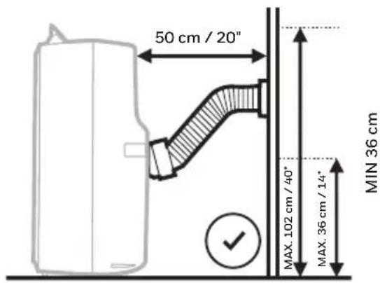
- Drill a hole through an outside wall or through a window pane. Respect the height and dimensions of the hole given in Fig. 1 and Fig. 2.
- Insert and secure the Flange Fixture + Hole Cover into the newly drilled hole.
- Fix one end of the Exhaust Hose into the Flange Fixture + Hole Cover that was secured on the wall.
- Fix the other end of the Exhaust Hose onto the Exhaust Hose Connector and then onto the rear Exhaust outlet of the unit (See Fig. 2).
Note: When the unit is not in use, remove the Exhaust Hose from the Flange Fixture on the wall and use the included Hole Cover to cover the hole on the wall.
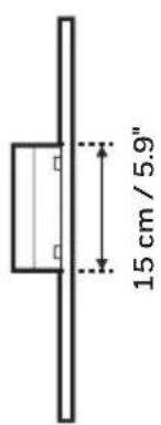
In the window panel
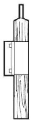
In the wooden kickboard of a french window
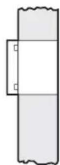
natural_image
Simple line drawing of a rectangular frame with two small square cutouts on the sides (no text or symbols)In the wall: we recommend you to insulate the section of wall using suitable insulation materials.
Fig.2Fig.1

Important:
Do not replace or lengthen the exhaust hose as this could cause the unit to malfunction.

natural_image
Simple line drawing of a pipe connection with a valve and cross symbol (no text or labels)
NOT RECOMMENDED RECOMMENDED
WARNING: Any warranties included with this product will be voided if an extra extension hose is added to the originally provided installation kit or if the installation is performed differently than the manufacturer's instructions, without proper consultation. Please contact Customer Support for help with installation procedures if needed.
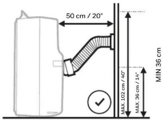
- The supplied exhaust hose has a diameter of 5.9 inches (15 cm) and can be extended from 12 inches to 47 inches (30 cm to 120 cm).
- Do not bend (to the extent shown below) the exhaust hose. A bent hose will block exhaust air and cause the unit to malfunction or shut-off.
- Make sure the back of the unit is at least 50 cm / 20 inches away from the wall. Do not place the unit in front of curtains or drapes as this could obstruct the airflow.
Note: Due to the power input of the unit on start up, voltage drops may occur and this can influence other equipment (e.g. dimming lights). Please make sure that the unit is connected to a supply with a maximum permissible system impedance Zmax = 0.306 Ohm. If you require further clarification, you may contact your local power supply authority.
CONTROL PANEL

1) Timer Control 4) Mode Control
2) Fan Speed Control 5) Power Control / Standby Mode
3) Timer / Temperature Set Controls 6) Warning Light (when flashing)
FUNCTION BUTTONS
POWER CONTROL

The Power Control turns the unit on and off. When the unit is plugged in, this button lights up indicating it is in a Standby Mode ready to be switched on anytime.
MODE CONTROL

Settings: Air Conditioning, Heating*, Dehumidifying, Fan.
The corresponding indicator light will illuminate to indicate the current mode setting.
• Air Conditioning Mode

Adjust fan speed and air temperature to suit your desired comfort level.
Temperature setting range is 16^ C - 32^ C ( 61^ F - 89^ F).
- Dehumidifying Mode

Air is dehumidified as it passes through the unit, without being in full cooling mode.
If room temperature is higher than 25^ C ( 77^ F) fan speed can be adjusted; otherwise fan speed is preset to LOW.
Note: If the unit will be used mainly as a dehumidifier, do not connect the exhaust hose.
Continuous drainage is then necessary (refer to Continuous Draining for Dehumidifier Mode).
*Applicable for models with Heating feature only.
FUNCTION BUTTONS (CONTINUED)
- Fan Mode

For air circulation without air conditioner cooling.
- Heating Mode*

This unit uses Heat-Pump technology which reverses the air conditioning cooling cycle by transferring heat from the outside into the room – this is more energy efficient than traditional electric heaters that generate heat instead of transferring heat into the room. These properties make this heater ideal for use in autumn or spring when outdoor temperatures are not severely cold, or as supplemental heating in colder rooms of your home.
When heating mode is selected the indicator light will shine. Heating is activated only when the ambient temperature is below 25^ C ( 77^ F). In this mode, the desired temperature can be set between 16^ C - 25^ C ( 61^ F - 77^ F).
Note: The exhaust hoses must vent outside the room when using heating mode.
IMPORTANT: The Heat pump draws moisture from the air which then condenses into the internal water tank. The unit will pause operation when the tank is full and will restart when the tank has been emptied. It is recommended to use the heating mode in a room with 50% humidity or lower. Avoid operating moisture-producing products or appliances such as a humidifier or a kettle when using the unit in heating mode.
See the “Draining Water Condensation in Heat Mode” section for more information on draining the water tank.
FAN SPEED CONTROL

3 settings: High, Medium and Low.
*Applicable for models with Heating feature only.
FUNCTION BUTTONS (CONTINUED)
TIMER CONTROL
While the unit is turned on, press the timer button then press the ▼ or ▲ to select the number of hours you would like the unit to continue to run. The unit will turn off automatically.
AUTO TURN OFF:
While unit is running, press the ▼ or ▲ button to select the number of hours you want the unit to run in air conditioning mode.
AUTO TURN ON:
When unit is in a standby mode (plugged in with power light on), then press the ▼ or ▲ button to select the number of hours until you want the unit to automatically start running.
TEMPERATURE / TIMER SET CONTROLS
• Used for adjusting the timer and thermostat.
• The default display is setting temperature.
- In cooling mode, when ▼ or ▲ button is pressed, the set temperature is displayed and may be adjusted. After 10 seconds the display will revert back to room temperature. Temperature is only adjustable in cool mode. The time is adjustable between 1 - 24 hours.
Note: By pressing both ▼ or ▲ buttons at the same time, the display will toggle between Celsius (°C) and Fahrenheit (°F).
WARNING LIGHT
Condensation may accumulate in the unit.
If the internal tank becomes full, the Power Control light will flash and the unit will not operate until the unit has been drained (refer to Water Condensation Drainage).
After switching the air conditioner off, you must wait 3 minutes before switching it back on again.
REMOTE CONTROL
The functions work the same as the Local Air Conditioner's Control Panel. All key functions can be accessed from the remote control.

flowchart
graph TD
    A["Power Control ON/OFF"] --> B["ON/OFF"]
    C["Fan Speed Control • HIGH • MID • LOW"] --> B
    D["Timer Control In running mode: Auto switch off In stand-by mode: Auto switch on Press ▼ or ▲ button to adjust the time setting for 1 hour intervals."] --> B
    E["Temperature / Timer Set"] --> F["• Used for adjusting the timer and temperature."]
    E --> G["• When the ▼ or ▲ key is pressed, the set temperature is displayed and may be adjusted"]
    E --> H["• Timer setting is available from 1 - 24 hours by pressing the key ▼ or ▲."]
    I["Mode Control"] --> J["Press this button to change the operation mode in the order of: Air Conditioning De-humidifying"]
    J --> K["Heating* ← Fan"]
    L["*Applicable for models with Heating feature only."] --> K
Note:
- Battery Installation: Remove the cover on the back of the remote control and insert two AAA batteries with + and - pointing in the proper direction according to the polarity markings.

Caution:
• Use only two AAA or IEC R03 1.5V batteries.
- Remove the batteries if the remote control is not in use for a month or longer.
- All batteries should be replaced at the same time, do not mix with old batteries.
- Do not mix alkaline, standard (carbon-zinc) or rechargeable (nickel-cadmium) batteries.
• Properly dispose of used batteries.
Appliance Maintenance:
- Turn off the appliance before disconnecting the power supply.
- Only clean the appliance with a soft dry cloth.
Dust Filter Maintenance:
The dust filter is to be cleaned every two weeks to maintain air cooling efficiency. Please follow the below instructions for cleaning the dust filters:
- Switch off and unplug the Air Conditioner from the electrical outlet.
- Remove the Upper Dust Filter and the Lower Dust Filter.
- Gently wash using water and/or diluted liquid dishwashing detergent. Rinse thoroughly and gently shake excess water from the filters. Make sure the filters are dry before reinstalling.
- Note: You may use a vacuum cleaner to remove dust. Replace the Upper Grill and the Lower Grill onto the unit.

natural_image
Line drawing of a portable air conditioner unit with ventilation grilles and fan (no text or symbols)WARNING: DO NOT power or operate the Air Conditioner when cleaning or when any or both of the Rear Grills are removed from the unit, or if there is a loose-fitting Rear Grill(s). DO NOT attempt to handle or touch any of the parts or wiring inside the air conditioner after the Rear Grill(s) are removed from the unit. Doing so can cause serious injury or electrical shock.
End of Season Storage & Maintenance:
If the appliance will not be used for a long time, follow these steps:
- Be sure to drain the left-over water condensation. Remove the lower drain plug and use a shallow pan to collect the water (make sure to replace the drain plug when finished).
- To dry excess moisture, run the unit in Fan only mode for 30 minutes before storing.
- Turn off and unplug the air conditioner from the power supply.
- Remove the dust filter and clean with water. Dry the dust filter and then reinstall.
Disconnecting the Window Installation Kit:5.
- Remove the Exhaust Hose from the unit by pulling away from the unit at the same time.
- Remove the Window Bracket, Window Bracket Panel Adapter and Exhaust Hose Connector.
- It is recommended to store the Window Kit parts in a bag together with the Remote Control and placing them together with the air conditioner unit.
-
If needed, you can clean the Window Kit with a damp cloth and water before storing. Make sure all parts of the Window Kit are dry before storage.
-
Cover the air conditioner with a cloth/plastic bag before storage, to protect from dust and scratches collecting on the surface of the unit.
- It is recommended to coil the power cord before storing to ensure the cord is protected from bents and creases.
- Store the air conditioner in a cool, dry place, away from direct sunlight.
WATER CONDENSATION DRAINAGE
When there is excess water condensation inside the unit, the air conditioner stops running and shows a warning light (the Power Control button flashes with a red light). This warning light indicates that the water condensation needs to be drained using the following procedures:
Manual Draining in Cooling, Dehumidifying and Heating\* Modes
Water may need to be drained in high humidity areas.
- Unplug the unit from power source.
- Place a shallow pan under the lower rubber drain plug. See diagram.
- Remove the lower rubber drain plug.
- Water will drain out and collect in the shallow pan.
- After the water is drained, replace the lower rubber drain plug firmly.
- You can now turn on the unit.

*Applicable for models with Heating feature only.
WATER CONDENSATION DRAINAGE (CONTINUED)
IMPORTANT: The water cannot be drained using the continuous drain option in heating* mode. In Heating mode, the internal water tank collects condensation faster and may require more frequent emptying of the tank in more humid rooms. It is recommended to use the heating mode in a room with 50% humidity or lower. Avoid operating moisture-creating products or appliances such as a humidifier or a kettle when using the unit in heating mode.
Continuous Draining for Dehumidifier Mode
While using the unit in dehumidifier mode, continuous drainage is recommended.
- Unplug the unit from power source.
- Remove the upper rubber drain plug. While doing this operation some residual water may spill so please have a pan to collect the water.
- Connect the drain connector to a 1/2" hose or standard garden hose (not included). See diagram.
- The water can be continuously drained through the hose into a floor drain or sink.
- You can now turn on the unit.

*Applicable for models with Heating feature only.
The following troubleshooting guide addresses the most common problems. If problems persist, call customer support. Unplug and disconnect the appliance from the power source before attempting to troubleshoot.
| PROBLEM POSSIBLE CAUSE SOLUTION | ||
| The air conditioning unit does not start | No electricity. Check for power. | |
| Batteries in the remote control need to be replaced. | Change remote control batteries. | |
| The power cord is not properly plugged in. | Remove and reconnect the power cord. | |
| Runs a short while only | The thermostat temperature setting is too close to room temperature. | Lower the set temperature. |
| Air outlet is blocked. Make sure the exhaust hose is properly connected. | ||
| There are tight bends in the air exhaust hose. | Connect exhaust hose as per instructions on page 3. | |
| In Heating Mode*,the unit keeps switching off frequently | The room is too humid. Water Tank needs to be emptied. | In heating mode, the heat pump condenses moisture from the air into the internal water tank. In more humid rooms, it will collect faster and need to be emptied out more frequently. It is recommended to use the heating mode in 50% humidity or less. Switch off any appliances such as a humidifier or kettle to avoid extra moisture build up in the room when operating in heating mode. |
*Applicable for models with Heating feature only.
TROUBLESHOOTING GUIDE (CONTINUED)
| PROBLEM POSSIBLE CAUSE SOLUTION | ||
| Runs but not cooling | A door or window is open. | Make sure the window or door is closed. |
| The dust filter is dirty. Clean the dust filter. | ||
| The exhaust hose is detached. | Reinstall exhaust hose properly (refer to Installation section). | |
| Temperature setting is too high. | Reduce temperature setting on control panel. | |
| Air outlet or intake is blocked. | Remove blockage. | |
| Room exceeds recommended size. | Move unit to smaller room. | |
| Large size or number of windows are decreasing cooling effectiveness. | Cover windows with curtains or blinds. | |
| Will not run and Power button is blinking (water full indicator) | Excess water condensation inside the tank. | Drain the water (refer to Water Condensation Drainage). |
TROUBLESHOOTING GUIDE (CONTINUED)
| PROBLEM POSSIBLE CAUSE SOLUTION | ||
| Heater* is not switching ON. | Heating function not activated yet.The ambient temperature is too high. | Check that the Heating function has been activated. will be illuminated when the Heater is switched ON. |
| Heating is activated only when the ambient temperature is below 25°C (77°F). | Switch on the Heating function when the ambient temperature reaches below 25°C (77°F). | |
*Applicable for models with Heating feature only.
| ERROR CODE ERROR POSSIBLE CAUSE | |
| "E1" Temperature sensor open circuit/short circuit. | |
| "E2"(for cooling and heating* model) | Copper tube sensor open circuit/short circuit. |
| "Lo" Temperature is below -9°C (32°F). | |
| “Hi” Temperature is over 50°C (99°F). | |
*Applicable for models with Heating feature only.
LIRE ET CONSERVER CES CONSIGNES
UNE MAUVAISE MANIPULATION PEUT CAUSER DE SERIEUX DOMMAGE AUX PERSONNES ET A L`APPAREIL. EN CAS D'INCOHERENCE OU DE CONFLIT ENTRE LA VERSION ANGLAISE ET TOUT AUTRE VERSION LINGUISTIQUE DU CONTENU DE CE MATERIEL, LA VERSION ANGLAISE PRÉVAUDRA.
AVERTISSEMENT:
natural_image
Simple line drawing of a water heater next to a window (no text or symbols)natural_image
Simple line drawing of a server unit and a geometric shape (no text or symbols)natural_image
Simple line drawing of two connected circles with a connecting rod, labeled 'x1' at bottom (no text or symbols on the shapes)②
x1 x1
③

4

natural_image
Pure diagram of a cylindrical object with evenly spaced radial lines, no text or symbols present.x1
5

x1
Kit d'installation:
natural_image
Line drawing of a portable air conditioner unit with a coiled tube inserted into the chamber (no text or symbols)natural_image
Line drawing of a portable air conditioner unit with a coiled hose inserted, no text or symbols presentnatural_image
Simple line drawing of a rectangular frame with two small square cutouts on the sides (no text or symbols)natural_image
Simple line drawing of a pipe connection with a valve and cross symbol (no text or labels)DÉCONSEILLÉ RECOMMANDÉ
Attention:
natural_image
Line drawing of a small air conditioner unit with ventilation grilles and heat sinks (no text or symbols)natural_image
Simple line drawing of a server room with a window and a grid on top (no text or symbols)natural_image
Simple line drawing of a server tower with a door symbol above it (no text or labels)Función Ventilador
Importante:
natural_image
Line drawing of a portable air conditioner unit with a coiled hose inserted into the chamber (no text or symbols)natural_image
Line drawing of a portable air conditioner unit with a coiled hose inserted, no text or symbols presentnatural_image
Simple line drawing of a vertical wooden object with a rectangular base and two small square markers (no text or symbols)natural_image
Simple line drawing of a rectangular object with a wavy top and two small square cutouts on the side (no text or symbols)natural_image
Simple line drawing of a pipe connection with a valve and cross symbol (no text or labels)
NO RECOMENDADO RECOMENDADO
Precaución:
natural_image
Line drawing of a portable air conditioner unit with ventilation grilles and fan (no text or symbols)natural_image
Simple line drawing of a server unit and a window with four square windows (no text or symbols)natural_image
Simple line drawing of a server unit with a door symbol above it (no text or labels)Ventilator stand
Belangrijk:
(Airconditioning Mode)
natural_image
Simple line drawing of two connected circles with a connecting rod, labeled 'x1' at the bottom (no text or symbols on the circles)②

x1 x1
③
4
natural_image
Pure diagram of a cylindrical object with evenly spaced radial lines, no text or symbols present.x1
5

x1
Installatie set:
natural_image
Line drawing of a portable air conditioner unit with a coiled tube inserted into the chamber (no text or symbols)Uitlaatslang:
Dia. 15cm (5.9")
Lengte: 30cm to 120cm (12" to 47")
natural_image
Line drawing of a portable air conditioner unit with a coiled hose inserted, no text or symbols presentnatural_image
Simple line drawing of a pipe outlet with a valve and cross symbol (no text or labels)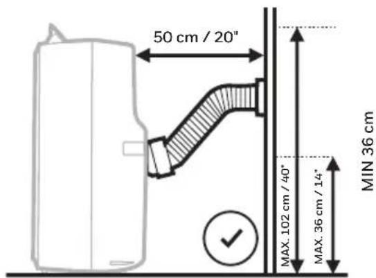
NIET AANBEVOLEN NIET AANBEVOLEN
Voorzichtigheid:
natural_image
Line drawing of a portable air conditioner unit with ventilation grilles and fan (no text or symbols)natural_image
Simple line drawing of a device with a window and four square windows (no text or symbols)natural_image
Simple line drawing of a server unit with a door symbol above it (no text or labels)Lüfterbetrieb
Wichtig:
natural_image
Simple line drawing of two connected circles with a connecting rod, labeled 'x1' at bottom (no text or symbols on the circles)②

x1 x1
③

4

natural_image
Pure diagram of a cylindrical object with evenly spaced radial lines, no text or symbols present.x1
5

x1
natural_image
Diagram of a cylindrical object with two side circular ends connected by a double-headed arrow, no text or symbols present.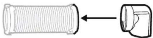
natural_image
Diagram showing a coiled pipe with a separate cylindrical component (no text or symbols)
natural_image
Technical line drawing of a threaded pipe fitting with a flanged end (no text or symbols)INSTALLATION (FORTSETZUNG)
natural_image
Line drawing of a portable air conditioner unit with a coiled tube inserted, showing airflow direction (no text or symbols)Abluftschlauch:
natural_image
Line drawing of a portable air conditioner unit with a coiled hose inserted, no text or symbols presentnatural_image
Simple line drawing of a pipe outlet with a valve and cross symbol (no text or labels)
Vorsicht:
natural_image
Line drawing of a portable air conditioner unit with ventilation grilles and fan (no text or symbols)natural_image
Simple line drawing of a water heater with a window and wheels (no text or symbols)natural_image
Simple line drawing of a server unit with a door symbol above it (no text or labels)natural_image
Simple line drawing of two connected circles with a connecting rod, labeled 'x1' at the bottom (no text or symbols on the circles)②
x1 x1
③

4

natural_image
Pure diagram of a cylindrical object with evenly spaced radial lines, no text or symbols present.x1
5
x1
natural_image
Diagram of a cylindrical object with two side circular ends connected by a double-headed arrow, no text or symbols present.
natural_image
Diagram showing a coiled pipe with a separate cylindrical component (no text or symbols)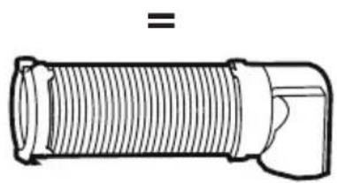
natural_image
Technical line drawing of a mechanical component with threaded body and flange (no text or symbols)natural_image
Line drawing of a portable air conditioner unit with a coiled tube inserted, showing airflow direction (no text or symbols)Tubo di Scarico
Dia. 15cm (5.9")
natural_image
Line drawing of a portable air conditioner unit with a coiled hose inserted, no text or symbols presentnatural_image
Simple line drawing of a rectangular frame with two small square cutouts on the left side (no text or symbols)natural_image
Simple line drawing of a pipe outlet with a valve and a cross symbol (no text or labels)Condensation may accumulate in the unit.
Attenzione:
natural_image
Line drawing of a portable air conditioner unit with ventilation grilles and fan (no text or symbols)natural_image
Simple line drawing of a server unit and a window with four windows (no text or symbols)natural_image
Simple line drawing of a tower with wheels and a window-like pattern above (no text or symbols)Fläktdrift
Viktig:
1) Kontrollpanel (Inkl. signalmottagare)
9) Fjärrkontroll
natural_image
Simple line drawing of two connected circles with a connecting rod, labeled 'x1' at the bottom (no text or symbols on the circles)②

x1 x1
③

4

natural_image
Pure diagram of a cylindrical object with evenly spaced radial lines, no text or symbols present.x1
5

x1
Installationssats:
flowchart
graph LR
    A["Single Component"] --> B["Cylinder 1"]
    B --> C["Cell with Outer Ring"]
    C --> D["Cylinder 2"]
    D --> E["Cell with Inner Ring"]
    E --> F["Final Product"]
INSTALLATION (FORTSÄTTNING)
natural_image
Line drawing of a portable air conditioner unit with a coiled tube inserted, showing airflow direction (no text or symbols)Kondensvattenslang:
Diameter: 15cm (5.9")
natural_image
Line drawing of a portable air conditioner unit with a coiled hose inserted, no text or symbols presentnatural_image
Simple line drawing of a pipe connection with a valve and cross symbol (no text or labels)
REKOMMENDERAS INTE REKOMMENDERAS
Varning:
natural_image
Line drawing of a small industrial air conditioner unit with ventilation grilles and fan (no text or symbols)1) Kontrolpanel (Inkl. signalmodtager)
9) Fjernbetjening
natural_image
Simple line drawing of two connected circles with a connecting rod, labeled 'x1' at the bottom (no text or symbols on the circles)②

x1 x1
③

4
natural_image
Pure diagram of a cylindrical object with evenly spaced radial lines, no text or symbols present.x1
5

x1
Installationssæt:
natural_image
Diagram of a cylindrical object with two side circular ends connected by a double-headed arrow, no text or symbols present.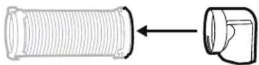
natural_image
Diagram showing a coiled pipe with a separate cylindrical component (no text or symbols)
natural_image
Technical line drawing of a threaded pipe fitting with a flanged end (no text or symbols)natural_image
Line drawing of a portable air conditioner unit with a coiled tube inserted into the chamber (no text or symbols)Udstødningsslange:
Dia. 15cm (5.9")
Length: 30cm to 120cm (12" to 47")
natural_image
Line drawing of a portable air conditioner unit with a coiled hose inserted, no text or symbols presentnatural_image
Simple line drawing of a pipe connection with a valve and cross symbol (no text or labels)ANBEFALES IKKE ANBEFALET

Advarsel:
natural_image
Line drawing of a portable air conditioner unit with ventilation grilles and ventilation grilles (no text or symbols)natural_image
Simple line drawing of a server unit and a window with four square windows (no text or symbols)natural_image
Simple line drawing of a server unit with a door symbol above it (no text or labels)Puhallintoiminto
Tärkeä:
natural_image
Simple line drawing of two connected circles with a connecting rod, labeled 'x1' at bottom (no text or symbols on the circles)②
x1 x1
③
4
natural_image
Pure diagram of a cylindrical object with evenly spaced radial lines, no text or symbols present.x1
5

x1
Asennuspakkaus:
natural_image
Diagram of a cylindrical object with two side flanges, connected by an arrow indicating direction (no text or symbols)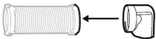
natural_image
Diagram showing a coiled pipe with a separate cylindrical component (no text or symbols)
natural_image
Technical line drawing of a threaded pipe fitting with a flanged end (no text or symbols)natural_image
Line drawing of a portable air conditioner unit with a coiled tube inserted, showing airflow direction (no text or symbols)Poistoletku:
Halk. 15cm (5.9")
Pituus: 30cm to 120cm (12" to 47")
natural_image
Line drawing of a portable air conditioner unit with a coiled hose inserted, no text or symbols presentnatural_image
Simple line drawing of a pipe connection with a valve and cross symbol (no text or labels)EI SUOSITELLA SUOSITELLAAN

varovaisuus:
natural_image
Line drawing of a portable air conditioner unit with ventilation grilles and fan (no text or symbols)natural_image
Simple line drawing of a mobile device with wheels and a window (no text or symbols)natural_image
Simple line drawing of a server tower with a door symbol above it (no text or labels)Wentylator
ilmoitus:
natural_image
Simple line drawing of two connected circles with a label 'x1' (no text or symbols on the circles)②
x1 x1
③

4

natural_image
Pure diagram of a cylindrical object with evenly spaced radial lines, no text or symbols present.x1
5

x1
natural_image
Pure diagram of a cylindrical object with two side connectors and an internal coil, no text or symbols present.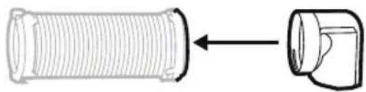
natural_image
Diagram showing a cylindrical pipe with a left-side arrow pointing to a separate cylindrical component (no text or symbols)
natural_image
Technical line drawing of a mechanical component with threaded ends and a flanged end (no text or symbols)INSTALACJA (KONTYNUAJCJA)
natural_image
Line drawing of a portable air conditioner unit with a coiled hose inserted into the chamber (no text or symbols)Wąż odprowadzający:
Dia. 15cm (5.9")
Length: 30cm to 120cm (12" to 47")
natural_image
Line drawing of a portable air conditioner unit with a coiled hose inserted, no text or symbols presentnatural_image
Simple line drawing of a rectangular frame with wavy top and bottom edges, no text or symbols present.natural_image
Simple line drawing of a pipe connection with a valve and cross symbol (no text or labels)NIEZALECANE ZALECANE
Varoitus:
natural_image
Line drawing of a portable air conditioner unit with ventilation grilles and fan (no text or symbols)natural_image
Simple line drawing of a water heater with a window and door (no text or symbols)natural_image
Simple line drawing of a server unit and a geometric shape (no text or symbols)Fan İşletimi
Önemli:
natural_image
Simple line drawing of two connected circles with a label 'x1' (no text or symbols on the circles)②

x1 x1
③

4

natural_image
Pure diagram of a cylindrical object with evenly spaced radial lines, no text or symbols present.x1
5

x1
Kurulum Kiti:
natural_image
Pure diagram of a cylindrical object with two side connectors and an internal striped pattern, no text or symbols present.
natural_image
Diagram showing a coiled pipe with a separate cylindrical component (no text or symbols)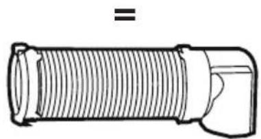
natural_image
Technical line drawing of a threaded pipe fitting with a flanged end (no text or symbols)natural_image
Line drawing of a portable air conditioner unit with a coiled hose inserted into the chamber (no text or symbols)Egzoz Hortumu:
Çap 15cm (5.9")
Uzunluk: 30cm to 120cm (12" to 47")
natural_image
Line drawing of a portable air conditioner unit with a coiled hose inserted, no text or symbols presentnatural_image
Simple line drawing of a wooden cylindrical object with a rectangular base, no text or symbols present.natural_image
Simple line drawing of a rectangular frame with two small square cutouts on the left side (no text or symbols)natural_image
Simple line drawing of a pipe connection with a valve and cross symbol (no text or labels)ÖNERİLMEZ ÖNERİLİR

Dikkat:
natural_image
Line drawing of a portable air conditioner unit with ventilation grilles and fan (no text or symbols)natural_image
Simple line drawing of a water heater with a window and wheels (no text or symbols)natural_image
Simple line drawing of a vertical container with wheels and a geometric shape above it (no text or symbols)natural_image
Line drawing of a portable air conditioner unit with a coiled tube inserted, showing airflow direction (no text or symbols)natural_image
Line drawing of a portable air conditioner unit with a coiled hose inserted, no text or symbols presentnatural_image
Simple line drawing of a rectangular object with a wavy top and a horizontal base, no text or symbols present.natural_image
Simple line drawing of a pipe outlet with a valve and a cross symbol (no text or labels)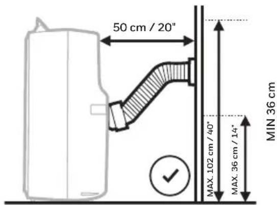
предосторожность:
natural_image
Line drawing of a portable air conditioner unit with ventilation grilles and fan (no text or symbols)natural_image
Simple line drawing of a water heater with a window and four windows (no text or symbols)natural_image
Simple line drawing of a server unit with a door symbol above it (no text or labels)1) Painel de Controlo (Inclui recetor de sinal)
9) Controlo Remoto
natural_image
Simple line drawing of two connected circles with a connecting rod, labeled 'x1' at the bottom (no text or symbols on the circles)②

x1 x1
③

4

natural_image
Pure diagram of a cylindrical object with evenly spaced radial lines, no text or symbols present.x1
5
x1
Kit de instalação:
flowchart
graph LR
    A["Pipe fitting"] --> B["Tube with coiled tube"]
    B --> C["Tube with coiled tube"]
    C --> D["Tube with coiled tube"]
    D --> E["Tube with coiled tube"]
    style A fill:#f9f,stroke:#333
    style E fill:#bbf,stroke:#333
    style B fill:#dfd,stroke:#333
    style C fill:#dfd,stroke:#333
    style D fill:#dfd,stroke:#333
    style E fill:#dfd,stroke:#333
natural_image
Line drawing of a portable air conditioner unit with a coiled hose inserted into the chamber (no text or symbols)Tubo de Exaustão:
Dia. 15cm (5.9")
natural_image
Line drawing of a portable air conditioner unit with a coiled hose inserted, no text or symbols presentnatural_image
Simple line drawing of a rectangular frame with two small square cutouts on the sides (no text or symbols)natural_image
Simple line drawing of a pipe outlet with a valve and cross symbol (no text or labels)
NÃO RECOMENDADO RECOMENDADO
Cuidado:
natural_image
Line drawing of a portable air conditioner unit with ventilation grilles and fan (no text or symbols)- Remova a mangueira de exaustão da unidade, puxando-a, ao mesmo tempo, para fora da unidade.
- Remove the Window Bracket, Window Bracket Panel Adapter and Exhaust Hose Connector.
- It is recommended to store the Window Kit parts in a bag together with the Remote Control and placing them together with the air conditioner unit.
-
If needed, you can clean the Window Kit with a damp cloth and water before storing. Make sure all parts of the Window Kit are dry before storage.
-
Cover the Honeywell Portable Local Air Conditioner with a cloth/ plastic bag before storage, to protect from dust and scratches collecting on the surface of the unit.
- It is recommended to coil the power cord before storing to ensure the cord is protected from bents and creases.
- Store the Honeywell Portable Local Air Conditioner in a cool, dry place, away from direct sunlight
natural_image
Symbol of a trash bin crossed with no text or numbers, representing waste sorting or disposal (no text present)
DK Apparatet må ikke bortskaffes med husholdningsaffald, men skal tages til et autoriseret affaldssorterings- og genbrugscenter.
FI Laitetta ei saa hävittää kotitalousjätteen mukana, vaan vietävä valtuutettuun jätteenkeräyslaitokseen.
PL Urządzenia nie wolno wyrzucać wraz z odpadami z gospodarstwa domowego, ale należy je oddać do autoryzowanego centrum utylizacji i recyklingu odpadów.
TR Cihaz ev atıkları ile birlikte çöpe atılarak elden çıkartılmamalı, yetkili bir atık ayrıştırma ve geri dönüşüm merkezine götürülmelidir.
RU Данное оборудование запрещается выбрасывать вместе с обычным бытовым мусором. Его необходимо сдавать в уполномоченные центры раздельного сбора мусора и вторичной переработки.
PT O aparelho não deve ser eliminado com resíduos domésticos, mas levado a um centro autorizado de separação e reciclagem de resíduos.
natural_image
Symbol of a trash bin crossed with no text or numbers, representing environmental restriction (no text present)
Feito na china
© 2019 JMATEK Limited, Iodos os direitos reservados. A marca comercial Honeywell é utilizada sob licença da Honeywell International Inc. Honeywell International Inc. não tem representação ou garantia a resposte dosto produto. Este produto é fabricado pela Airtek Intl Corp. Ltd. (subsidiária da JMATEK Ltd.).
RU Сделано в Китве
© 2019 MATEK Limited, Ltd. Все права защищины.
Торгован марка Honeywell используется по лицензили
Honeywell International Inc.
Honeywell International Inc. не является
представителем или гарантом данного
продукта. Этот продукт изготовлен Airtek Int'l Corp. Ltd.
(JMATEK Международная группа компаний)
Çin de üretilmiştir
© 2019 JMATEK Limited, Ltd. Her hakkı sakıdir. The Honeywell markası, Honeywell International Inc. lisansı altındadır. Honeywell International Inc. bu Ürünle ilgili temsil yada garanti vermez. Bu ürün Airtek Int'l Corp. Ltd. tarafından üretilmiştir. (JMATEK Uluslar Arası Şirkeller Grubu)
PI Wyprodukowane w Chinach
© 2019 JMATEK I limited. Wszystkie prawa zastrzeżone.
Honeywell Znak towarowy jest używany na podstawie Licencji Honeywell International Inc
Honeywell International Inc nie ponosi odpowiedzialności lub gwarancji w odnieseniu do tego produktu.
Produkt ten wytwarzany jest przez Airtek Int'l Corp Ltd. (zależna JMATEK Ltd.).
Valmistettu Kiinassa
© 2019 JMATEK Limited. Ltd. Kaikki oikeudet pidatetaan. Honeywell on lisensicitu luotenerkki Honeywell International Incite. Honeywell International Inc. El vastaa laitteen takuusta. Tuotteen on valmistanut Airtek Int'l Corp. Ltd. (ytäryhtio JMATEK Ltd.).
DK Fremstilleti Kina
© 2019 JMATEK Limited. Alle rettigheder forbeholdes. Honeywell Trademark bruges under licens fra Honeywell International Inc. Honeywell International Inc. laver ingen forestillinger eller garantier med hensym til dette produkt. Dette produkt er fremstillet af Artek Int'l Corp Ltd (datterselskab af JMATEK Ltd.).
SE Tillerkad i Kina
© 2019 JMATEK Limited. Alla rättigheter reserverade. Honeywell Varumarket går under licens från Honeywell International Inc. Honeywell International Inc. är inte ansvariga för representation eller garantier för denna produkt. Denna produkt har konstruerats av Airtek Int'l Corp. Ltd. (dotterbolag till JMATEK Ltd.).
Made in P.R.C.
© 2019 JMATEK Limited. Tutti i diritti riservati.
Il Marcho Honeywell è usato sotto licenza concesa da Honeywell International Inc.
Honeywell International Inc. non rilascia alcuna dichiarazione o garanzia relativamente a questo prodotto.
Questo prodotto è fabbricato da Airtek Int'l Corp. Ltd.
(filtale di JMATEK Ltd.).
DE Hergestellt in China
© 2019 JMATEK Limited. Alle Rechte vorbehallen.
Die Honeywell Handelsmarke wird laut Lizenz unter
Honeywell International Inc. Verwendet.
Honeywell International Inc. macht keine Darstellungen oder
Garantien in Bezug auf dieses Produkt.
Dieses Produkt ist durch Airtek Int'l Corp. Ltd.
(Tochlargesellschaft der JMATEK Ltd.).
NI Made in P.R.C.
© 2018 JMATEK Limited. Alle rechten voorbehouden.
De Honeywell handelsmerk wordt gebruikt onder licentie van Honeywell International Inc.
Honeywell International Inc. doet geen verklaringen of garanties met betrekking tot dit product.
Dit product wordt vervaardigd door Airtek Int'l Corp. Ltd. (dochterondernaming van JMATEK Ltd.).
ES Hecho en China
© 2019 JMATEK Limited. Todos los derechos reservados.
La marca Honeywell es usada bajo licencia de Honeywell International Inc. Honeywell International Inc. no representa ni garantiza este producto.
Este producto es fabricado por Airtek Int'l Corp. Ltd. (subsidiaria de JMATEK Limited).
ED Fabriqué en Chine
© 2019 JMATEK Limited. Tous droits réservés.
La marque déposée Honeywell est utilisée en vertu d'une licence de Honeywell International Inc.
Honeywell International Inc. ne fait aucune déclaration et ne donne aucune garantie à l'égard de ce produit.
Ce produit est fabriqué par Airtek Int'l Corp. Itée (une filiale de JMATEK Limited).
EN Made in China
© 2019 JIMATEK Limited. All rights reserved.
The Honeywell Trademark is used under license
from Honeywell International Inc.
Honeywell International Inc. makes no
representations or warranties with respect to this product.
This product is manufactured by Airtek Intl Corp. Ltd.
(subsidiary of JIMATEK Ltd.).
JMATEK Limited
Manulife Financial Centre, Kwun Tong, Hong Kong Phone: 852-2559-5522 Email: info@jmatek.com Web: www.jmatek.com

- EN Local Air Conditioner
- FR Climatiseur Local
- SE Lokal Luftkonditionering
- READ AND SAVE THESE INSTRUCTIONS
- WARNING:
- Additional warnings for appliances with R290 refrigerant gas.
- USER TIPS
- Important:
- Installation Kit:
- Installation Steps:
- Through an Open Window
- INSTALLATION (CONTINUED)
- Through a Drilled Hole in the Wall or Window
- CONTROL PANEL
- FUNCTION BUTTONS
- POWER CONTROL
- MODE CONTROL
- FUNCTION BUTTONS (CONTINUED)
- FAN SPEED CONTROL
- TIMER CONTROL
- AUTO TURN OFF:
- AUTO TURN ON:
- TEMPERATURE / TIMER SET CONTROLS
- WARNING LIGHT
- REMOTE CONTROL
- Note:
- Caution:
- Appliance Maintenance:
- Dust Filter Maintenance:
- End of Season Storage & Maintenance:
- WATER CONDENSATION DRAINAGE
- Manual Draining in Cooling, Dehumidifying and Heating\* Modes
- WATER CONDENSATION DRAINAGE (CONTINUED)
- Continuous Draining for Dehumidifier Mode
- TROUBLESHOOTING GUIDE (CONTINUED)
- LIRE ET CONSERVER CES CONSIGNES
- AVERTISSEMENT:
- Kit d'installation:
- Attention:
- Importante:
- Precaución:
- Belangrijk:
- Installatie set:
- Voorzichtigheid:
- Wichtig:
- INSTALLATION (FORTSETZUNG)
- Vorsicht:
- Attenzione:
- Viktig:
- Installationssats:
- INSTALLATION (FORTSÄTTNING)
- Varning:
- Installationssæt:
- Advarsel:
- Tärkeä:
- Asennuspakkaus:
- varovaisuus:
- ilmoitus:
- INSTALACJA (KONTYNUAJCJA)
- Varoitus:
- Önemli:
- Kurulum Kiti:
- Dikkat:
- предосторожность:
- Kit de instalação:
- Cuidado:
- JMATEK Limited
Brand : HONEYWELL
Model : MN10CESWW
Category : Air conditioner