
HR4013C - Drill MAKITA - Free user manual and instructions
Find the device manual for free HR4013C MAKITA in PDF.

| Product type | Rotary hammer drill |
| Brand | Makita |
| Model | HR4013C |
| Power | Electric, corded |
| Voltage | 230 V |
| Frequency | 50 Hz |
| Input power | 1,050 W |
| Drilling capacity (concrete) | 32 mm |
| Drilling capacity (steel) | 13 mm |
| Drilling capacity (wood) | 32 mm |
| Chuck | SDS-Max |
| No load speed | 0 - 390 rpm |
| Blow rate | 0 - 2,600 blows/min |
| Impact energy | 6.2 J |
| Weight | 6.7 kg |
| Length | 456 mm |
| Height | 216 mm |
| Width | 93 mm |
| Power cable | 5 m |
| Anti-vibration system | AVT (Anti-Vibration Technology) |
| Functions | Reversible rotation, safety clutch, variable speed |
| Maintenance | Regular cleaning of ventilation slots, carbon brush replacement |
| Safety | Lock-on switch, overload protection |
| Spare parts | Carbon brushes, tool holder, switch available |
| Repairability | Designed to be repairable, spare parts available |
| General information | Instruction manual included, 2-year warranty |
Frequently Asked Questions - HR4013C MAKITA
User questions about HR4013C MAKITA
0 question about this device. Answer the ones you know or ask your own.
Ask a new question about this device
Download the instructions for your Drill in PDF format for free! Find your manual HR4013C - MAKITA and take your electronic device back in hand. On this page are published all the documents necessary for the use of your device. HR4013C by MAKITA.
USER MANUAL HR4013C MAKITA
GB Rotary Hammer Instruction Manual
natural_image
Line drawings of two different types of electric drill motors (no text or symbols present)

natural_image
Technical line drawing of a mechanical device with labeled component (1), no readable text or symbols beyond label1
2
3
4
5
6
natural_image
Technical line drawing of a mechanical component with a labeled part (2), showing internal structure without any text or symbols.7
8
natural_image
Pure technical line drawings of mechanical components without any text or symbols9
003139
10
014034
11 12
014027 003150
13 14
014879014878
15 16
014090 014091
17 18
014033
014135
natural_image
Line drawing of a hand holding a drill bit in a 3D room (no text or symbols)19 20
014030
002449
natural_image
Line drawing of a hand using a power tool to trigger sparks (no text or symbols)21
014031
ENGLISH (Original instructions)
| Explanation of general view | ||
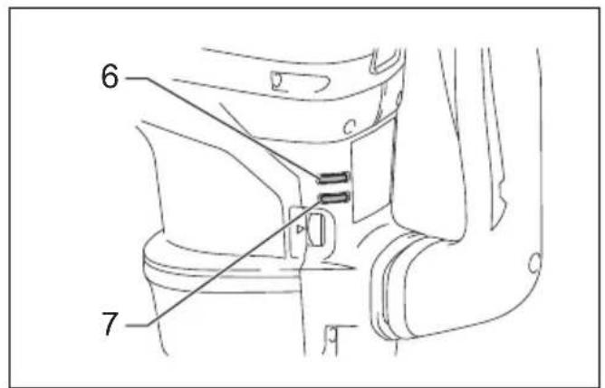
| 1 Switch trigger | 7 Service indicator lamp (red) | 14 Release cover |
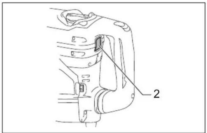
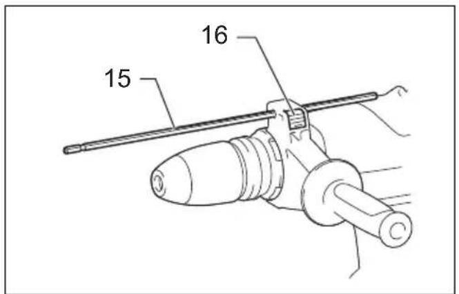
| 2 Switch button | 8 Side handle | 15 Depth gauge |
| 3 Adjusting dial | 9 Clamp nut | 16 Lock button |
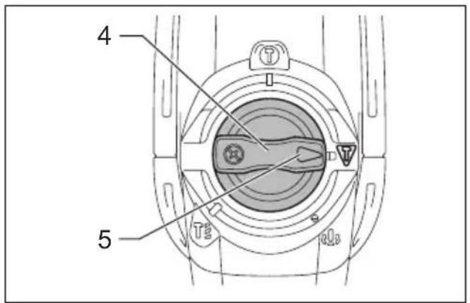
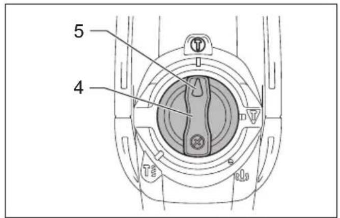
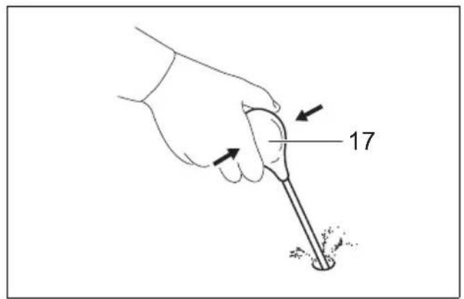
| 4 Change lever | 10 Side grip | 17 Blow-out bulb |
| 5 Pointer | 11 Bit shank | |
| 6 Power-ON indicator lamp (green) | 12 Bit grease | |
| 13 Bit | ||
SPECIFICATIONS
| Model HR4003C HR4013C HR5202C HR5212C | |||||
| Capacities | Carbide-tipped bit 40 mm 52 mm | ||||
| Core bit 105 mm 160 mm | |||||
| No load speed (min ^-1 ) 250 – 500 150 – 310 | |||||
| Blows per minute | 1,450 – 2,900 | 1,100 – 2,250 | |||
| Overall length | 479 mm 599 mm | ||||
| Net weight | 6.2 – 6.4 kg | 6.8 – 6.9 kg | 10.9 – 11.1 kg | 11.9 – 12.0 kg | |
| Safety class | ☐/II | ||||
- Due to our continuing program of research and development, the specifications herein are subject to change without notice.
- Specifications may differ from country to country.
- The weight may differ depending on the attachment(s). The lightest and heaviest combination, according to EPTA-Procedure 01/2014, are shown in the table.
ENE044-1
Intended use
The tool is intended for hammer drilling in brick, concrete and stone as well as for chiselling work.
ENF002-2
Power supply
The tool should be connected only to a power supply of the same voltage as indicated on the nameplate, and can only be operated on single-phase AC supply. They are double-insulated and can, therefore, also be used from sockets without earth wire.
GEA010-2
General power tool safety warnings
WARNING Read all safety warnings, instructions, illustrations and specifications provided with this power tool. Failure to follow all instructions listed below may result in electric shock, fire and/or serious injury.
Save all warnings and instructions for future reference.
The term “power tool” in the warnings refers to your mains-operated (corded) power tool or battery-operated (cordless) power tool.
GEB243-1
ROTARY HAMMER SAFETY WARNINGS
Safety instructions for all operations
- Wear ear protectors. Exposure to noise can cause hearing loss.
-
Use auxiliary handle(s), if supplied with the tool. Loss of control can cause personal injury.
-
Hold the power tool by insulated gripping surfaces, when performing an operation where the cutting accessory may contact hidden wiring or its own cord. Cutting accessory contacting a "live" wire may make exposed metal parts of the power tool "live" and could give the operator an electric shock.
Safety instructions when using long drill bits with rotary hammers
-
Always start drilling at low speed and with the bit tip in contact with the workpiece. At higher speeds, the bit is likely to bend if allowed to rotate freely without contacting the workpiece, resulting in personal injury.
-
Apply pressure only in direct line with the bit and do not apply excessive pressure. Bits can bend, causing breakage or loss of control, resulting in personal injury.
ADDITIONAL SAFETY RULES
- Wear a hard hat (safety helmet), safety glasses and/or face shield. Ordinary eye or sun glasses are NOT safety glasses. It is also highly recommended that you wear a dust mask and thickly padded gloves.
- Be sure the bit is secured in place before operation.
-
Under normal operation, the tool is designed to produce vibration. The screws can come loose easily, causing a breakdown or accident. Check tightness of screws carefully before operation.
-
In cold weather or when the tool has not been used for a long time, let the tool warm up for a while by operating it under no load. This will loosen up the lubrication. Without proper warm-up, hammering operation is difficult.
- Always be sure you have a firm footing. Be sure no one is below when using the tool in high locations.
- Hold the tool firmly with both hands.
- Keep hands away from moving parts.
- Do not leave the tool running. Operate the tool only when hand-held.
- Do not point the tool at any one in the area when operating. The bit could fly out and injure someone seriously.
- Do not touch the bit, parts close to the bit, or workpiece immediately after operation; they may be extremely hot and could burn your skin.
- Some material contains chemicals which may be toxic. Take caution to prevent dust inhalation and skin contact. Follow material supplier safety data.
- Do not touch the power plug with wet hands.
SAVE THESE INSTRUCTIONS.

WARNING:
DO NOT let comfort or familiarity with product (gained from repeated use) replace strict adherence to safety rules for the subject product. MISUSE or failure to follow the safety rules stated in this instruction manual may cause serious personal injury.
FUNCTIONAL DESCRIPTION

CAUTION:
- Always be sure that the tool is switched off and unplugged before adjusting or checking function on the tool.
Switch action

CAUTION:
- Before plugging in the tool, always check to see that the switch trigger actuates properly and returns to the "OFF" position when released.
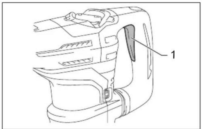
Switch trigger (Fig. 1)
This switch functions when setting the tool in ▼ symbol and ▶ symbol modes.
To start the tool, simply pull the switch trigger. Release the switch trigger to stop.
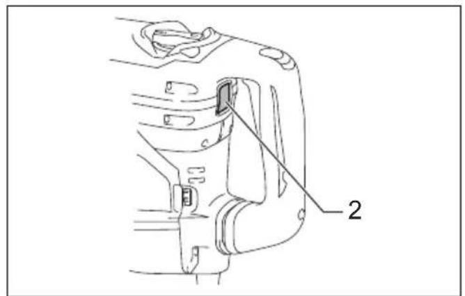
Switch button (Fig. 2)
This switch functions when setting the tool in Ⓞ symbol mode.
When the tool is in the Ⓤ symbol mode, the switch button projects out and lights in red.
To start the tool, press the switch button. The switch light turns in green.
To stop the tool, press the switch button again.
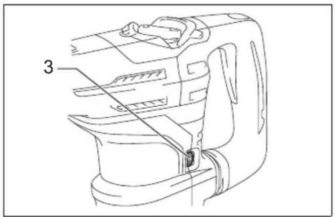
Speed change (Fig. 3)
The revolutions and blows per minute can be adjusted just by turning the adjusting dial. The dial is marked 1 (lowest speed) to 5 (full speed).
Refer to the table below for the relationship between the number settings on the adjusting dial and the revolutions/blows per minute.
For Model HR4003C, HR4013C
| Number on adjusting dial | Revolutions per minute | Blows per minute |
| 5 500 2,900 | ||
| 4 470 2,700 | ||
| 3 380 2,150 | ||
| 2 290 1,650 | ||
| 1 250 1,450 |
014134
For Model HR5202C, HR5212C
| Number on adjusting dial | Revolutions per minute | Blows per minute |
| 5 310 2,250 | ||
| 4 290 2,100 | ||
| 3 230 1,700 | ||
| 2 180 1,300 | ||
| 1 150 1,100 |
014872
For Model HR4013C, HR5212C only
NOTE:
- Blows at no load per minute becomes smaller than those on load in order to reduce vibration under no load, but this does not show trouble. Once operation starts with a bit against concrete, blows per minute increase and get to the numbers as shown in the table. When temperature is low and there is less fluidity in grease, the tool may not have this function even with the motor rotating.

CAUTION:
- If the tool is operated continuously at low speeds for a long time, the motor may get overloaded, resulting in tool malfunction.
- The speed adjusting dial can be turned only as far as 5 and back to 1. Do not force it past 5 or 1, or the speed adjusting function may no longer work.
Selecting the action mode

CAUTION:
- Do not rotate the change lever when the tool is running. The tool will be damaged.
- To avoid rapid wear on the mode change mechanism, be sure that the change lever is always positively located in one of the action mode positions.
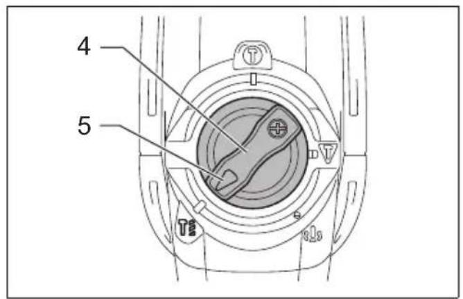
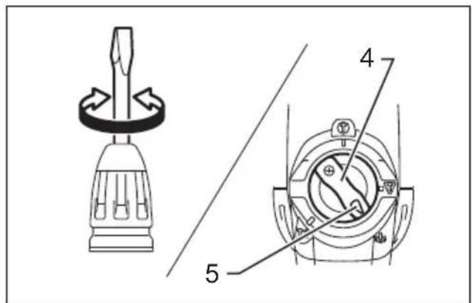
Hammer drilling mode (Fig. 4)
For drilling in concrete, masonry, etc., rotate the change lever to the symbol. Use a tungsten-carbide tipped bit.
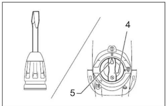
Hammering mode (Switch trigger mode) (Fig. 5)
For chipping, scaling or demolition operations, rotate the change lever to the ▼ symbol. Use a bull point, cold chisel, scaling chisel, etc.
Hammering mode (Switch button mode)
For continuous chipping, scaling or demolition operations, rotate the change lever to the symbol.
(Fig. 6)
The switch button projects out and lights in red.
Use a bull point, cold chisel, scaling chisel, etc. (Fig. 7)
NOTE:
- When using the tool in the symbol mode, the switch trigger does not work but only the switch button works.
Torque limiter
The torque limiter actuates when torque reaches a certain level. The motor disengages from the output shaft. When this happens, the bit stops turning.

CAUTION:
- As soon as the torque limiter actuates, switch off the tool immediately. This helps to prevent premature wear of the tool.
Indicator lamp (Fig. 8)
The green power-ON indicator lamp lights up when the tool is plugged in. If the indicator lamp does not light up, the mains cord or the controller may be defective.
When the indicator lamp lights up but the tool does not start even the tool is switched on, the carbon brushes may be worn out, or the controller, the motor or the ON/OFF switch may be defective.
If above symptoms occur, stop using the tool immediately and ask your local service center.
The red service indicator lamp lights up when the carbon brushes are nearly worn out to indicate that the tool needs servicing. After some period of use, the motor automatically shuts off.
ASSEMBLY

CAUTION:
- Always be sure that the tool is switched off and unplugged before carrying out any work on the tool.
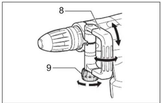
Side handle

CAUTION:
- Use the side handle only when chipping, scaling or demolishing. Do not use it when drilling in concrete, masonry, etc. The tool cannot be held properly with this side handle when drilling. (Fig. 9)
The side handle can be swung 360^ on the vertical and secured at any desired position. It also secures at eight different positions back and forth on the horizontal. Just loosen the clamp nut to swing the side handle to a desired position. Then tighten the clamp nut securely. (Fig. 10)
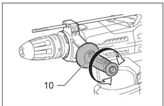
Side grip (Fig. 11)

CAUTION:
• Always use the side grip to ensure operating safety when drilling in concrete, masonry, etc.
The side grip swings around to either side, allowing easy handling of the tool in any position. Loosen the side grip by turning it counterclockwise, swing it to the desired position and then tighten it by turning clockwise.
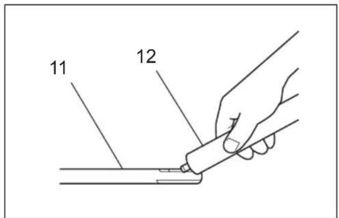
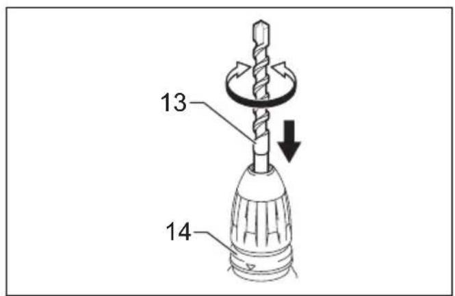
Installing or removing the bit
Clean the bit shank and apply bit grease before installing the bit. (Fig. 12)
Insert the bit into the tool. Turn the bit and push it in until it engages.
If the bit cannot be pushed in, remove the bit. Pull the release cover down a couple of times. Then insert the bit again. Turn the bit and push it in until it engages.
After installing, always make sure that the bit is securely held in place by trying to pull it out. (Fig. 13)
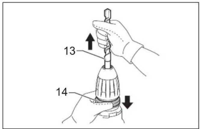
To remove the bit, pull the release cover down all the way and pull the bit out. (Fig. 14)
Bit angle (when chipping, scaling or demolishing)
The bit can be secured at 24 different angles. To change the bit angle, rotate the change lever so that the pointer points to the symbol. Turn the bit to the desired angle.
(Fig. 15)
Rotate the change lever so that the pointer points to the symbol. Then make sure that the bit is securely held in place by turning it slightly. (Fig. 16)
Depth gauge
The depth gauge is convenient for drilling holes of uniform depth.
Press and hold the lock button, and insert the depth gauge into the hex hole. (Fig. 17)
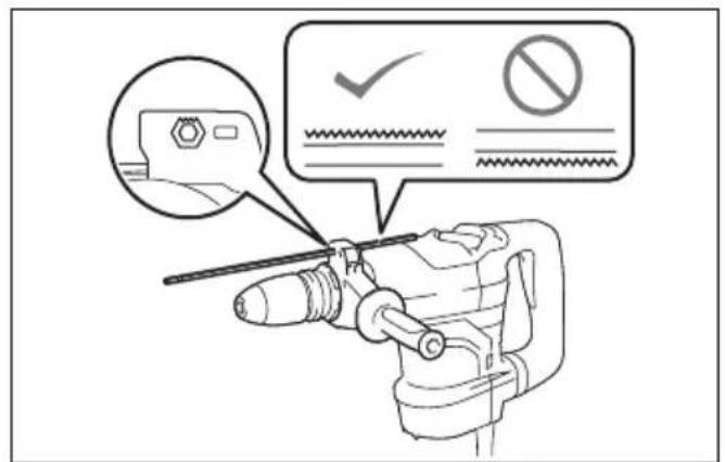
Make sure the toothed side of the depth gauge faces the marking. (Fig. 18)
Adjust the depth gauge by moving it back and forth while pressing the lock button. After adjustment, release the lock button to lock the depth gauge.
NOTE:
- The depth gauge cannot be used at the position where the depth gauge strikes against the gear housing/motor housing.
OPERATION

CAUTION:
- Make sure the work material is secured and not unstable. Flown object may cause personal injury.
- Do not pull the tool out forcibly even the bit gets stuck.
Loss of control may cause injury.
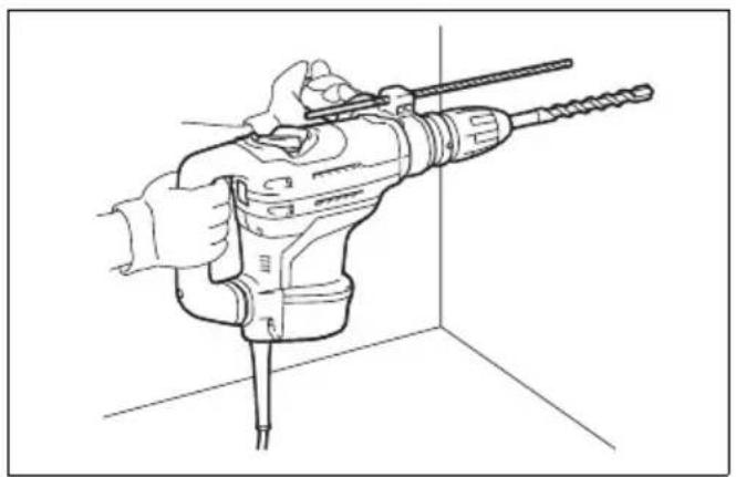
Hammer drilling operation (Fig. 19)
Set the change lever to the symbol.
Position the bit at the desired location for the hole, then pull the switch trigger.
Do not force the tool. Light pressure gives best results. Keep the tool in position and prevent it from slipping away from the hole.
Do not apply more pressure when the hole becomes clogged with chips or particles. Instead, run the tool at an idle, then remove the bit partially from the hole. By repeating this several times, the hole will be cleaned out and you can continue drilling operation.

CAUTION:
- There is a tremendous and sudden twisting force exerted on the tool/bit at the time of hole breakthrough, when the hole becomes clogged with chips and particles, or when striking reinforcing rods embedded in the concrete. Always use the side grip (auxiliary handle) and firmly hold the tool by both side grip and switch handle during operations, and maintain good balance and safe footing. Failure to do so may result in the loss of control of the tool and potentially severe injury.
Blow-out bulb (optional accessory) (Fig. 20)
After drilling the hole, use the blow-out bulb to clean the dust out of the hole.
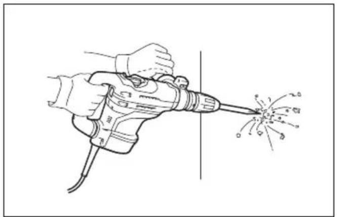
Chipping/Scaling/Demolition (Fig. 21)
Set the change lever to the or symbol.
Hold the tool firmly with both hands. Turn the tool on and apply slight pressure on the tool so that the tool does not bounce around, uncontrolled. Pressing very hard on the tool will not increase the efficiency.
MAINTENANCE

CAUTION:
- Always be sure that the tool is switched off and unplugged before attempting to perform inspection or maintenance.
- Never use gasoline, benzine, thinner, alcohol or the like. Discoloration, deformation or cracks may result.
Lubrication

CAUTION:
- This servicing should be performed by Makita Authorized Service Centers only.
This tool requires no hourly or daily lubrication because it has a grease-packed lubrication system. It should be relubricated regularly. Send the complete tool to Makita Authorized or Factory Service Center for this lubrication service.
To maintain product SAFETY and RELIABILITY, repairs, any other maintenance or adjustment should be performed by Makita Authorized Service Centers, always using Makita replacement parts.
OPTIONAL ACCESSORIES

CAUTION:
- These accessories or attachments are recommended for use with your Makita tool specified in this manual. The use of any other accessories or attachments might present a risk of injury to persons. Only use accessory or attachment for its stated purpose.
If you need any assistance for more details regarding these accessories, ask your local Makita Service Center.
• SDS-MAX Carbide-tipped bits
- SDS-MAX bull point
• SDS-MAX cold chisel
• SDS-MAX scaling chisel
- SDS-MAX clay spade
- Hammer grease
- Bit grease
- Side handle
- Side grip
- Depth gauge
- Blow-out bulb
- Carrying case
- Dust extractor attachment
NOTE:
- Some items in the list may be included in the tool package as standard accessories. They may differ from country to country.
ENG905-1
Noise
The typical A-weighted noise level determined according to EN62841-2-6:
Model HR4003C
Sound pressure level ( L_pA ): 95 dB (A)
Sound power level ( L_WA ): 103 dB (A)
Uncertainty (K): 3 dB (Å)
Model HR4013C
Sound pressure level ( L_pA ): 96 dB (A)
Sound power level ( L_WA ): 104 dB (A)
Uncertainty (K): 3 dB (A)
Model HR5202C, HR5212C
Sound pressure level ( L_pA ): 101 dB (A)
Sound power level ( L_WA ): 109 dB (A)
Uncertainty (K): 3 dB (A)
ENG907-1
NOTE:
- The declared noise emission value(s) has been measured in accordance with a standard test method and may be used for comparing one tool with another.
- The declared noise emission value(s) may also be used in a preliminary assessment of exposure.
WARNING:
- Wear ear protection.
- The noise emission during actual use of the power tool can differ from the declared value(s) depending on the ways in which the tool is used especially what kind of workpiece is processed.
- Be sure to identify safety measures to protect the operator that are based on an estimation of exposure in the actual conditions of use (taking account of all parts of the operating cycle such as the times when the tool is switched off and when it is running idle in addition to the trigger time).
ENG900-1
Vibration
The vibration total value (tri-axial vector sum) determined according to EN62841-2-6:
Model HR4003C
Work mode: chiseling function with side handle Vibration emission ( a_h,CHeq ): 7.6 m/s ^2 Uncertainty (K): 1.5 m/s ^2
Work mode: chiseling function with side grip Vibration emission ( a_h,CHeq ): 7.3 m/s ^2 Uncertainty (K): 1.5 m/s ^2
Work mode: hammer drilling into concrete Vibration emission ( a_h,HD ): 10.1 m/s ^2 Uncertainty (K): 1.5 m/s ^2
Model HR4013C
Work mode: chiseling function with side handle Vibration emission ( a_h,CHeq ): 4.8 m/s ^2 Uncertainty (K): 1.5 m/s ^2
Work mode: chiseling function with side grip Vibration emission ( a_h,CHeq ): 4.7 m/s ^2 Uncertainty (K): 1.5 m/s ^2
Work mode: hammer drilling into concrete Vibration emission ( a_h,HD ): 5.7 m/s ^2 Uncertainty (K): 1.5 m/s ^2
Model HR5202C
Work mode: chiseling function with side handle Vibration emission ( a_h,CHeq ): 9.9 m/s ^2 Uncertainty (K): 1.5 m/s ^2
Work mode: chiseling function with side grip Vibration emission ( a_h,CHeq ): 9.9 m/s ^2 Uncertainty (K): 1.5 m/s ^2
Work mode: hammer drilling into concrete Vibration emission ( a_h,HD ): 15.7 m/s ^2 Uncertainty (K): 2.0 m/s ^2
Model HR5212C
Work mode: chiseling function with side handle
Vibration emission ( a_h, CHeq ): 7.2 m/s ^2
Uncertainty (K): 1.5 m/s²
Work mode: chiseling function with side grip
Vibration emission ( a_h, CHeq ): 7.5 m/s ^2
Uncertainty (K): 1.5 m/s²
Work mode: hammer drilling into concrete
Vibration emission (a _h, HD ): 9.9 m/s ^2
Uncertainty (K): 1.5 m/s²
ENG901-2
NOTE:
- The declared vibration total value(s) has been measured in accordance with a standard test method and may be used for comparing one tool with another.
- The declared vibration total value(s) may also be used in a preliminary assessment of exposure.

WARNING:
- The vibration emission during actual use of the power tool can differ from the declared value(s) depending on the ways in which the tool is used especially what kind of workpiece is processed.
- Be sure to identify safety measures to protect the operator that are based on an estimation of exposure in the actual conditions of use (taking account of all parts of the operating cycle such as the times when the tool is switched off and when it is running idle in addition to the trigger time).
DECLARATIONS OF CONFORMITY
For European countries only
The Declarations of conformity are included in Annex A to this instruction manual.
Descriptif
DÉCLARATIONS DE CONFORMITÉ
Incertezza (K): 2,0 m/s²
Modello HR5212C
OPTIONELE ACCESSOIRES
LET OP:
- Intended use
- Power supply
- General power tool safety warnings
- ROTARY HAMMER SAFETY WARNINGS
- Safety instructions for all operations
- Safety instructions when using long drill bits with rotary hammers
- ADDITIONAL SAFETY RULES
- SAVE THESE INSTRUCTIONS.
- WARNING:
- FUNCTIONAL DESCRIPTION
- CAUTION:
- Switch action
- Switch trigger (Fig. 1)
- Switch button (Fig. 2)
- Speed change (Fig. 3)
- For Model HR4013C, HR5212C only
- NOTE:
- Selecting the action mode
- Hammer drilling mode (Fig. 4)
- Hammering mode (Switch trigger mode) (Fig. 5)
- Hammering mode (Switch button mode)
- (Fig. 6)
- Torque limiter
- Indicator lamp (Fig. 8)
- ASSEMBLY
- Side handle
- Side grip (Fig. 11)
- Installing or removing the bit
- Bit angle (when chipping, scaling or demolishing)
- (Fig. 15)
- Depth gauge
- OPERATION
- Hammer drilling operation (Fig. 19)
- Blow-out bulb (optional accessory) (Fig. 20)
- Chipping/Scaling/Demolition (Fig. 21)
- MAINTENANCE
- Lubrication
- OPTIONAL ACCESSORIES
- Noise
- Model HR4003C
- Model HR4013C
- Model HR5202C, HR5212C
- Vibration
- Model HR5202C
- Model HR5212C
- DECLARATIONS OF CONFORMITY
- For European countries only
- DÉCLARATIONS DE CONFORMITÉ
- Modello HR5212C
- OPTIONELE ACCESSOIRES
- LET OP:
Brand : MAKITA
Model : HR4013C
Category : Drill