
20039 - Welding machine GUDE - Free user manual and instructions
Find the device manual for free 20039 GUDE in PDF.


| Product type | MMA arc welding machine |
| Brand | Güde |
| Model | 20039 |
| Category | Welding machine |
| Power supply | 230 V / 50 Hz |
| Welding current | 20 - 200 A |
| Electrode diameter | 1.6 to 4.0 mm |
| Duty cycle | 60% at 200 A, 100% at 160 A |
| Dimensions | 35 × 20 × 25 cm |
| Weight | 15 kg |
| Main functions | Arc welding with covered electrode, intensity adjustment, thermal protection |
| Maintenance and cleaning | Regularly clean ventilation openings, check connections and cables |
| Safety | Overcurrent and overheating protection, integrated RCD, mandatory use of gloves and welding mask |
| Spare parts and repairability | Electrodes, cables, electrode holder, ground clamps available as spare parts |
| General information | 106-page user manual, in French, available for free download |
Frequently Asked Questions - 20039 GUDE
User questions about 20039 GUDE
0 question about this device. Answer the ones you know or ask your own.
Ask a new question about this device
Download the instructions for your Welding machine in PDF format for free! Find your manual 20039 - GUDE and take your electronic device back in hand. On this page are published all the documents necessary for the use of your device. 20039 by GUDE.
USER MANUAL 20039 GUDE
natural_image
Icon of an open book inside a black circle (no text or symbols)Deutsch 4
Translation of original operating instructions
Français 17
natural_image
Exterior view of a portable electronic testing machine with cables and connectors (no visible text or labels)MIG 175 ZW/A

natural_image
Exterior view of a portable industrial testing machine with cables and sensors (no visible text or labels)MIG 175 ZD/A

natural_image
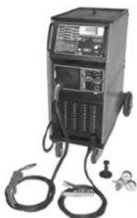
Exterior view of a portable welding machine with coiled cables and a power plug (no visible text or symbols)MIG 190
KOMBI/A
natural_image
Exterior view of a black industrial welding machine with cables and sensors (no visible text or labels)MIG 220 ZD/A

natural_image
Exterior view of a portable electronic testing machine with cables and sensors (no visible text or labels)MIG 250 ZD/A

natural_image
Exterior view of a black industrial testing machine with hoses and control panel (no visible text or symbols)MIG 350 ZD/A
CE




natural_image
Hand holding a black electronic device with a small square button, labeled '5' in the corner (no other text or symbols visible)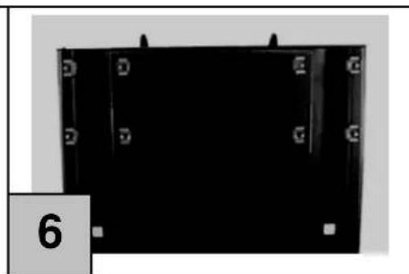
natural_image
Black rectangular object with corner markings and a small number '6' on the left side (no readable text or symbols)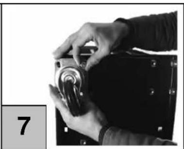
natural_image
Close-up of hands operating a mechanical component with a numbered label '7' in the corner (no readable text or symbols on the object itself)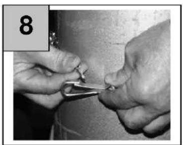
natural_image
Close-up of hands using a tool to cut or apply a small object, no visible text or symbols
natural_image
Close-up of a mechanical device with pressure gauge and tubing (no visible text or symbols)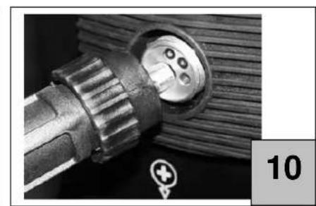
natural_image
Close-up of a mechanical component with threaded shaft and circular end, no visible text or symbols
natural_image
Close-up of mechanical components and tools in a lab setting (no visible text or symbols)
natural_image
Close-up of a mechanical device with no visible text or symbols
natural_image
Close-up of a mechanical device with glass components and wiring, no visible text or symbols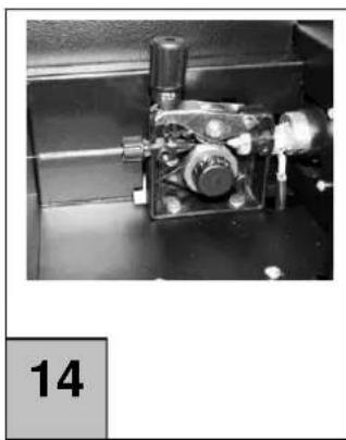
natural_image
Close-up of a mechanical component with no visible text or symbols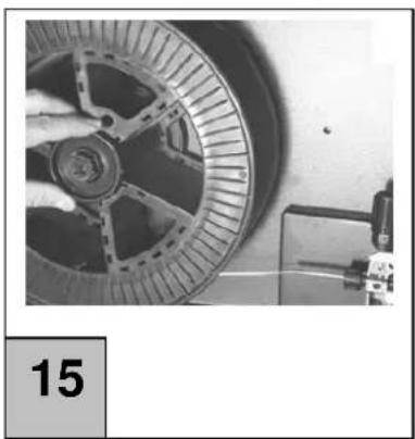
natural_image
Close-up of a car wheel assembly with a hand operating it, no visible text or symbols
Einführung
natural_image
Close-up of a black industrial machine with coiled black cables and two metal clips attached (no visible text or symbols)natural_image
Close-up of a black industrial device with coiled cable and two metal clips attached (no visible text or symbols)LED = Gelbe Thermoschutz-LED
Drahtgeschwindig-
EC Declaration of Conformity
We herewith declare,
Birkichstraße 6, 74549 Wolpertshausen, Germany
That the following Appliance complies with the appropriate basic safety and health requirements of the EC Directive based on its design and type, as brought into circulation by us.
In a case of alternation of the machine, not agreed upon by us, this declaration will lose its validity.
Machine Description:
Artikel-Nr.:
Article-No.:
- 20036
20038
- 20039
- 20040
- 20042
- 20044
Applicable EC Directives: - 2004/108/EEG
Applicable harmonized
- EN 60974-10
Standards:
Ort/Place:
Technical Documentation:
MIG welding units are not demanding as to the space, they are manufactured on the latest technical knowledge and therefore, most reliable. The welding generator consist of an air-cooled transformer and a double primary coil. The DC voltage will be obtained by using an air-cooled multi-diode bridge. *
A thermal switch protects the transformer against overloading. The plates are protected to withstand the conditions usual for welding. The ammeters fitted on the units of the series show the instant welding current.
Welding current set-up
(MIG 175ZW/A - MIG 175ZD/A
By means of a primary coil switch for combining the output, the generator may control as many as eight set-ups of the output. (Fig. 1/E)
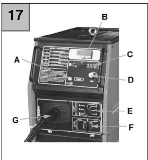
A. MENU selection pushbutton
B. Thermal fuse yellow LED
C. Display :
- wire movement speed
- wire start-up time
- wire extrusion following welding
- tack welding time
- thermal overloading fuse
D. Potentiometer
E. Degree switching
F. Hose pack central connection
Welding current set-up
MIG 190 KOMBI/A)
By means of a primary coil switch for combining the output, the generator may control as many as eight set-ups of the output. (Fig. 2/E/F)
A. MENU selection pushbutton
B. Thermal fuse yellow LED
C. Display :
- wire movement speed
- wire start-up time
- wire extrusion following welding
- tack welding time
- thermal overloading fuse
D. Potentiometer
E. Degree switching
F. Hose pack central connection
G. 230V/400V switching
Welding current set-up
(MIG 220ZD/A - MIG 250ZD/A
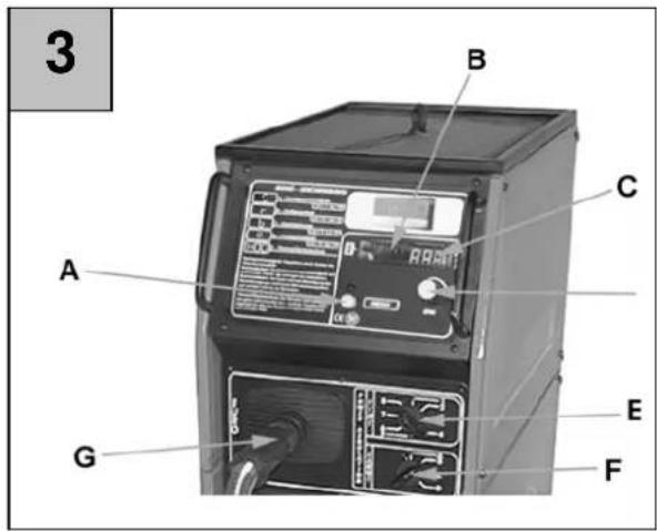
By means of two switches for combining the output, the generator may control as many as 32 set-ups of the output (Fig. 3/E/F)
A. MENU selection pushbutton
B. Thermal fuse yellow LED
C. Display :
-wire movement speed
-wire start-up time
-wire extrusion following welding
-tack welding time
-thermal overloading fuse
D. Potentiometer
E. Hose pack central connection
F. Main degrees switch
G. Intermediate degrees switch
Welding current set-up
(MIG 350ZD/A)
By means of two switches for combining the output, the generator may control as many as 32 set-ups of the output (Fig. 4/E/F)
A. MENU selection pushbutton
B. Thermal fuse yellow LED
C. Display :
-wire movement speed
-wire start-up time
-wire extrusion following welding
-tack welding time
-thermal overloading fuse
D. Potentiometer
E. Hose pack central connection
F. Main degrees switch
G. Intermediate degrees switch
Putting machine in operation
Options
The unit (MIG 175 ZW/A, MIG 190 Kombi/A with two-phase 400 V/230 V and an adaptor) is factory-adjusted for one-phase current supply, frequency 50/60 Hz, 230 V. The unit (MIG 175ZD/A, MIG 220ZD/A, MIG 250ZD/A, MIG 350ZD/A) is factory-adjusted for two-phase current supply, frequency 50/60 Hz, 400 V.
Two following works should be done:
Plug assembly (except for MIG 175 ZW/A a MIG 190 Kombi/A)
Wheel assembly
Bottle assembly
Hose pack assembly
Wire coil fit
Plug assembly
MIG 175 ZD/A, MIG 220 ZD/A and MIG 250 ZD/A units should be connected to a CEE-16 A plug (not included) On MIG 350 ZD/A, CEE-32 A plug (not included) is recommended (to be fitted with a ground wire. That should be done by a skilled person.
Notice: A thermal fuse is provided on the machine to give the transformer overload protection and to switch the machine off when it is overheated. After a time of cooling down, the machine is ready for use again.
Wheels mounting
The slide is provided to have two rotary front wheels fitted on it and to carry an axle for attaching two fixed rear wheel. . A tool bag is delivered with contents as follows: rotary front wheel, fixed rear wheels axle, rear wheels, pins, cotter keys and a cage nut. Screw the cage nut in respective devices, see Fig. 5 and 6. Fit in the front wheels according to Fig. 7. Insert the axle to fit the rear wheels and fix it using the cotter keys.
Bottle assembly
Put the bottle vertically on the holder surface and let it to stand on the holder, then fix it with a chain and spring hooks as shown in Fig. 8 Screw a pressure gauge on the bottle and put a grip tube (see Fig. 9) on the gauge and the electric valve using a clip.
Hose pack mounting
To connect the hose pack, it will be sufficient to firmly screw together the pack and EURO central connection on the front side (Fig. 10). In this way, you will effect the electrical connection and gas connection to the bottle
Wire coil fit
Put the wire coil on the hub and insert the wire in the drawing device, Fig. 11. Any model without exception will accommodate coils of weight 5 kg and 15 kg. The hub ha a coupling fitted to provide for the correct tension of the wire.
Wire tensioning motor
Make sure that the wire feed pulley has a guidance groove corresponding to the wire diameter. The machines are equipped with a wire winding of 0.6 and 0.8. The diameter is embossed on the side of the winding
Wire guidance
Cut the initial 10 cm of the wire off and make sure that the end is straight, free of any protrusions, deformations and impurities. The wire tensioning device moving arm may be opened by loosing the screw on the arm, see Fig. 12. Insert the wire in respective guidance groove and close the pressure arm again. Set the optimum resistance on hub 15 (the wire should be let pulled easily from the winding, however, not unwinding by itself). Set the thrust using a screw on the pressure arm (Fig. 14).
Setting up 230/400 V (Model „MIG 190 Kombi/A“ only)
The welding machine may be operated with both 230 V and 400 V. Make sure that the voltage changing switch (230/400 V) position complies with the selected plug.
Accident prevention regulations
Welding poses many risks to the operator and the viewers.
Personal precautions!
- Wear suitable clothing of pure cotton – shirts without any pockets and pants without turn-ups.
• Always wear insulating gloves.
- Wear heavy-duty insulating shod boots.
- To protect your eyes, wear protective mask and filter and clear glass goggles to be protected on sides. Caution, do not inhale fumes from welding!
• Make sure that the working area is properly ventilated. If necessary, in poky spaces in particular, use a good extraction plant.
- Clean the parts to be welded of rust, fats and paints to prevent smoke from material during the welding job. Where necessary, use a welding spray.
- Short circuit hazard! Check the mains for protection against overloading and short-circuiting and make sure that suitable grounding facilities are provided. Make sure that the mains voltage corresponds to that, which the machine is designed for.
- Make sure that there are no damaged or bare cables on the device. Where necessary, replace the mains cable, hose pack or the welding cable.
- Make a good connection with the ground.
- Never put a cable from the hose pack or the ground around your body. Do not take the hoses to aim at yourself or other people.
- Never get down to a welding job in wet or humid environment.
- Never work on the machine without the side protection device.
• Explosion hazard! Never work in proximity of readily flammable materials or easily inflammable tanks.
- Place the machine on the floor in a way providing for a stable position of the machine.
• The gas bottle should be fixed to the machine using a suitable chain, at a safe distance from any sources of heat.
- Never expose the welding machine to weather condition and do not store it in wet places. Electronic structural elements could be spoiled by a short circuit or corrosion.
Welding
Regular mode welding.
Caution: Take care to see that the tack welding facility (see table p.8) is switched off safely. Prepare the piece to be welded, lay bare the welded spots and ensure a good contact with the ground. Pushing the switch on the hose pack on enable the welding transformer and the wire movement.
Tip: Make a trial weld and set the machine so that you can hear and even and full "welding sound". In addition, pay attention to the burn-in depth of the weld to make a strong connection.
Tack welding
Proceeding according to the description, prepare the material to be welded and the tack welding jet nozzle (cylindrical nozzle with set corners), slip it on the burner neck. Put the tack welding device on (Fig. 2/C) and make trial welds. Caution: when tack welding, the hose pack switch has to be held pushed!
Burn Back
When the electric arc goes off, a melted metal drop will be created at the tip of the welding electrode, which often tends to

natural_image
Close-up of a black industrial machine with coiled cable and clamp, no visible text or symbols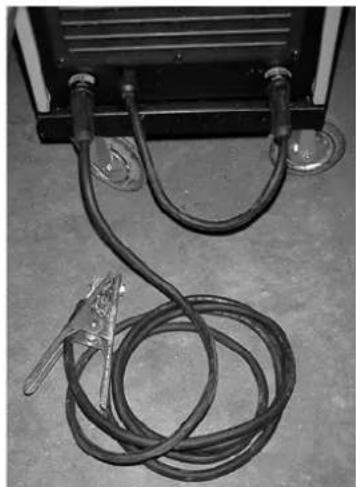
natural_image
Close-up of a black industrial lamp with coiled cable and two metal clips attached (no text or symbols visible)stick to the jet nozzle on the burner neck. Owing to the Burn Back set-up, the wire electrode will extrude a few millimetres (Fig. 2/C) and stick to the jet nozzle is thus avoided.
Wire movement speed (see table, p. 9)
To get a nice and neat weld, the electric arc should not splatter and obstruct the wire movement (see table p. 8) and should be set so that the resulting is a harmonic "welding sound".
Gas pressure
This rule should apply: wire thickness x 10 = l/min.
Example: wire thickness 0.8 mm x 10 = ca 8 l/min.
1.0 mm x 10 = ca 10 l/min
1.0 mm x 10 = ca. 10 litre./min.
thermal fuse yellow LED
Display = shows welding parameters
ENC = potentiometer
S1 = MENU selection pushbutton - used to select parameters
Type of Welding
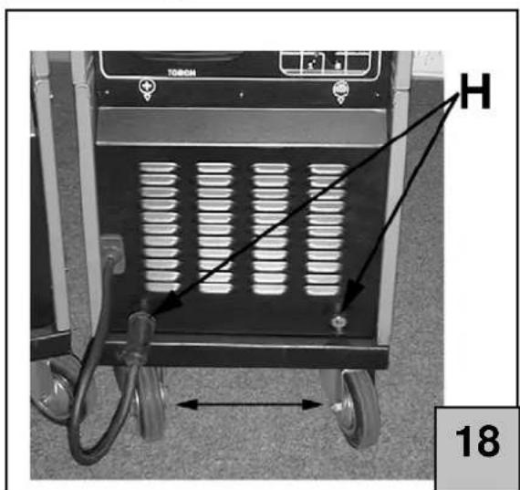
For core wire electrode welding, the pulverised gas is enclosed in the wire electrode And thus the gas bottle is not required. However, the polarity of the machine has to be changed, see Fig. 18.
MIG, MAG Welding
MIG = Metal Inert Gas MAG = Metal Active Gas
Both the methods are alike, i.e. only the type of the gas used is changed.
For MIG welding, argon (an inert gas) is used.
For MAG welding CO₂ (active gas) is used.
Information on Welding
Electronic control panel
- The machine welding functions may be controlled by use of the control panel.
- On switching the machine on, the control panel display shows the last measured value of the welding current.
Symbols legend
LED = thermal fuse yellow LED
Display = shows welding parameters
ENC = potentiometer
S1 = MENU selection pushbutton - used to select parameters

flowchart
graph TD
    A["LED/thermal protection"] --> B(( ))
    C["Display"] --> D(( ))
    E["S1"] --> F(( ))
    G["MENU button"] --> H(( ))
    I["ENC/Potentiometer"] --> H
Type of Welding
a) Manual
Pushing the button on the burner, the wire movement for manual welding will start or stop.
b) Tack welding
Holding the button on the burner, the machine will be welding for a set-up time (set-up 4.12 f) and then it will stop automatically. Re-pushing the button on the burner, the procedure may be repeated as required.
Welding parameters display
Pushing menu S1 button, it is possible to select any required setup during the welding operation. Set values may be increased/decreased by using the potentiometer.


Wire movement speed
-> display range -> display range -> range -> range min=05 - max.=99 min=10 - max.=99 min=0 - max.=99 min=10 - max.=80
Wire start up time
Wire extrusion after
Tack welding welding
Thermal fuse time
Symbols Glossary
This default may be recalled by push menu S1 button:
| c) |  | Wire Feed Speed: control by turning potentiometer /ENC |
| d) |  | Wire Start up Time: the wire feed speed set up earlier in point c) is reached gradually in order to reduce the start up current. |
| e) |  | Electrode extrusion after welding: When welding is finished, the wire keeps extruding for a moment to avoid sticking to the jet nozzle. |
| f) |  | Tack welding time: adjustment using potentiometer/ENC; for procedure see z b) |
| g) |  | Thermal fuse/overloading fuse: The operator should wait to see the yellow LED to go off, that being a signal of the transformer cool down. (The red sign on the display will fade away in several seconds) |
If you want to delete "Default" sign on the display, follow the procedure described below:
- Set the welding machine main switch on 0.
- Push menu S1button
- Switch the welding machine on and hold the S1 button pushed for 3 seconds.
On welding: useful tips
General Rules
If welding is set to the minimum, the electric arc should be short. This will be achieved by holding the hose pack as close to the piece to be welded as possible and setting the inclination to ca 60°. The arc length may be slowly increased as the current value gets higher; a distance of ca 20 mm may be achieved as a maximum.
General Advice
Various mistakes may occur in the course of welding. The mistakes may be avoided if the advice shown below is taken :
♦ Porosity
Small pores in the weld – similar to those on a bar of chocolate surface - may cause interruption of the gas flow and sometimes, they may even catch up small foreign bodies.
If that happens, our advice is to suspend welding and start welding again. However, it is primarily important to regain control of the gas flow rate (ca 8 litres per minute), thoroughly clean the work area and incline the hose pack in the right way during the work.
♦ Spattering
Small drops of melted metal dripping away from the welding arc. Small quantities cannot be excluded, however the phenomenon may be reduced to the minimum by correct current and gas flow rate adjustment and keeping the hose pack clean.
♦ Narrow and Round Welding
Results from the hose pack moving too fast or from wrong adjustment of the gas flow rate.
♦ Thick and Wide Welding
Results from the hose pack moving too slowly.
♦ Burnt Wire Rear End
May result from slow electrode move, loose or worn electrode guide, poor quality of the electrode or too high value of the supplied current.
♦ Burn-in Too Small
Is typically caused by the hose pack moving too fast, too low value of the supplied current, incorrect inclination, confused polarity or insufficient distance of the welded-on edges. Check the set welding parameters and improve the pre-treatment of the parts to be welded.
♦ Part Burn-through
May result from the hose pack moving too slowly, too high value of the supplied current or poor guiding of the electrode.
♦ Arc Instability
Is typically caused by insufficient voltage, irregular move of the electrode, too small amount of the protective gas.
Warranty
Warranty as shown in the warranty certificate attached!
The warranty shall not apply to damages resulting from:
- Transport or handling
- Improper use of the machine by the operator
• Insufficient maintenance - Defects, malfunction and cracks caused by the machine operation
• Breakdowns of electric and electronic components, electric motors - Unauthorised/unqualified use of the machine by the operator
Diagnostics of faults
| FAULT CAUSE TROUBLE SHOOTING | ||
| The wire will not move when the driving 1) guide contamination wheel is turning2) the winch coupling too high - loose3) damaged hose pack . | Blow off with air at the point of jet nozzlecheck the electrode core | |
| Electrode supply 1) Damaged contact jet nozzle replace intermittent/ gets disconnected 2) Burnt parts of contact jet nozzle replace3) Contaminated driving wheel groove replace4) Worn driving wheel fluted replace | ||
| Arc went off ? | 1) Poor contact of ground clamps and the piece to be welded2) short circuit between the pipe and the gas line | tighten and check the clampClean or replace the contact jet nozzle and the gas line nozzle |
| Porous weld | 1) Insufficient gas protection due to the deposit in gas line jet nozzle | Remove the deposit |
| 2) Poor distance or poor inclination | Distance between the mm, the inclination should | blower bulb of the hose pack and the piece to be welded should be 5 – 10be 60 |
| 3) Too little gas | Increase gas supply | |
| 4) Pieces to be welded wet | dry up using a hot air | pistol or in another way |
| After a long time of operation, the In result of prolonged operation, the Leave the machine to cool down for 20-30 minutes at least. Machine has suddenly stooped Machine got overheated and the thermal fuse switched on | ||
EC Declaration of Conformity
We herewith declare,
Birkichstraße 6, 74549 Wolpertshausen, Germany
That the following Appliance complies with the appropriate basic safety and health requirements of the EC Directive based on its design and type, as brought into circulation by us.
In a case of alternation of the machine, not agreed upon by us, this declaration will lose its validity.
Machine Description:
Technical Documentation:
natural_image
Close-up of a black industrial device with coiled black cables and metal clamp, mounted on a floor (no visible text or symbols)natural_image
Close-up of a black industrial lamp with coiled cable and two clamps attached (no visible text or symbols)EC Declaration of Conformity
Nous,
Güde GmbH & Co. KG
We herewith declare,
That the following Appliance complies with the appropriate basic safety and health requirements of the EC Directive based on its design and type, as brought into circulation by us.
In a case of alternation of the machine, not agreed upon by us, this declaration will lose its validity.
Machine Description:
Applicable EC Directives:
- 2006/95/EG la
- 2004/108/EEG
Applicable harmonized
Standards:
- EN 60974-1
- EN 60974-10
Ort/Place:
Technical Documentation:
natural_image
Close-up of a black industrial electrical device with coiled wires and clamps, no visible text or symbolsnatural_image
Close-up of a black industrial lamp with coiled cable and metal clips, no visible text or symbolsEC Declaration of Conformity
We herewith declare,
Birkichstraße 6, 74549 Wolpertshausen, Germany
That the following Appliance complies with the appropriate basic safety and health requirements of the EC Directive based on its design and type, as brought into circulation by us.
In a case of alternation of the machine, not agreed upon by us, this declaration will lose its validity.
Makine tipi:
Machine Description:
- Kaynak makinesi
Ürün no.:
Article-No.:
- 20036
20038
- 20039
- 20040
- 20042
- 20044
Applicable EC Directives: - 2004/108/EEG
Technical Documentation:
imza sahibi:
Title of Sinatory:
J. Bürkle FBL; QS
ÚVOD
natural_image
Close-up of a black industrial machine with coiled cable and clamp, mounted on a concrete floor (no visible text or symbols)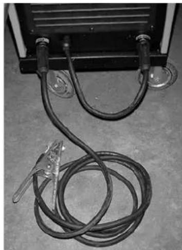
natural_image
Close-up of a black industrial machine with coiled cable and two metal clips attached (no visible text or symbols)1,0 mm x 10 = cca 10 l/min.
Plyn
EC Declaration of Conformity
We herewith declare,
Birkichstraße 6, 74549 Wolpertshausen, Germany
That the following Appliance complies with the appropriate basic safety and health requirements of the EC Directive based on its design and type, as brought into circulation by us.
In a case of alternation of the machine, not agreed upon by us, this declaration will lose its validity.
Machine Description:
Applicable EC Directives: - 2004/108/EEG
Technical Documentation:
natural_image
Close-up of a black industrial device with coiled cable and clamp, placed on a flat surface (no visible text or symbols)Zváranie plynom

natural_image
Close-up of a black industrial device with coiled cable and two connectors, no visible text or symbolsZváranie plniacim drôtom
1,0 mm x 10 = ca. 10 l/min.
Plyn
EC Declaration of Conformity
We herewith declare,
Birkichstraße 6, 74549 Wolpertshausen, Germany
That the following Appliance complies with the appropriate basic safety and health requirements of the EC Directive based on its design and type, as brought into circulation by us.
In a case of alternation of the machine, not agreed upon by us, this declaration will lose its validity.
Machine Description:
Applicable EC Directives: - 2004/108/EEG
Technical Documentation:
natural_image
Close-up of a black industrial machine with coiled cable and clamp, mounted on a floor (no visible text or symbols)natural_image
Close-up of a black electrical lamp with coiled wires and metal clips, placed on a concrete floor (no text or symbols visible)1.0 mm x 10 = ca. 10 l/min
Gas
- Meng- resp. beschermgas CO 2/argon => alle ijzermetalen
- Zuiver argon = >aluminium
EC Declaration of Conformity
Hiermee verklaren wij, Güde GmbH & Co. KG
We herewith declare,
Birkichstraße 6, 74549 Wolpertshausen, Germany
That the following Appliance complies with the appropriate basic safety and health requirements of the EC Directive based on its design and type, as brought into circulation by us.
In a case of alternation of the machine, not agreed upon by us, this declaration will lose its validity.
Machine Description:
- Beschermgaslasapparaten
Artikel nr.:
Article-No.:
- 20036
- 20038
- 20039
- 20040
- 20042
- 20044
Applicable EC Directives:
- 2006/95/EG
- 2004/108/EEG
Applicable harmonised
Standards:
- EN 60974-1
- EN 60974-10
Plaats/Place:
natural_image
Close-up of a black industrial device with coiled cable and clamp, no visible text or symbolsnatural_image
Close-up of a black industrial electrical component with coiled wires and two metal clips attached (no visible text or symbols)1.0 mm x 10 = circa 10 l/min
1,0 mm x 10 = ca. 10 ltr./min
Gas
EC Declaration of Conformity
We herewith declare,
Birkichstraße 6, 74549 Wolpertshausen, Germany
That the following Appliance complies with the appropriate basic safety and health requirements of the EC Directive based on its design and type, as brought into circulation by us.
In a case of alternation of the machine, not agreed upon by us, this declaration will lose its validity.
Machine Description:
Applicable EC Directives:
- 2006/95/EG
- 2004/108/EEG
Applicable harmonized
Standards:
- EN 60974-1
- EN 60974-10
Luogo /Place:
Date/Authorized Signature::
Technical Documentation:
natural_image
Close-up of a black industrial device with coiled cable and clamp, mounted on a floor (no visible text or symbols)
natural_image
Close-up of a black industrial electrical component with coiled wires and metal clips, placed on a concrete floor (no text or symbols visible)Tilkopling for dekkgassbetjening
1,0 mm x 10 = ca. 10 liter/min.
Gass
- Blandings- eller dekkgass CO
Rent argon
2/argon => Alle jernmetall
=
Aluminium
EC Declaration of Conformity
Vi erklærer herved, Güde GmbH & Co. KG
We herewith declare,
Birkichstraße 6, 74549 Wolpertshausen, Tyskland
That the following Appliance complies with the appropriate basic safety and health requirements of the EC Directive based on its design and type, as brought into circulation by us.
In a case of alternation of the machine, not agreed upon by us, this declaration will lose its validity.
Machine Description:
Artikkelnummer: - 20036
Article-No.: - 20038
- 20039
- 20040
- 20042
- 20044
Gjeldende EU-direktiver: - 2006/95/EG
Applicable EC Directives: - 2004/108/EEG
Anvendte harmoniserte
normer: - EN 60974-1
Applicable harmonized - EN 60974-10
Standards:
Sted Place:
Dato/produsentens underskrift:
Date/Authorized Signaure:
Undertegnedes tittel:
Title of Sinatory:
Technical Documentation:
Undertegnedes tittel:
Title of Sinatory:
J. Bürkle FBL; QS
INLEDNING
natural_image
Close-up of a black industrial device with coiled cable and clamp, placed on a floor (no visible text or symbols)natural_image
Close-up of a black industrial electrical component with coiled wires and two metal clips attached (no visible text or symbols)EC Declaration of Conformity
We herewith declare,
Birkichstraße 6, 74549 Wolpertshausen, Germany
That the following Appliance complies with the appropriate basic safety and health requirements of the EC Directive based on its design and type, as brought into circulation by us.
In a case of alternation of the machine, not agreed upon by us, this declaration will lose its validity.
Machine Description:
Applicable EC Directives:
- 2006/95/EG
- 2004/108/EEG
Applicable harmonized
Standards:
- EN 60974-1
- EN 60974-10
Plats /Place:
Technical Documentation:
natural_image
Close-up of a black industrial device with coiled cable and two metal clips attached (no visible text or symbols)natural_image
Close-up of a black electrical device with coiled black cables and metal clips, placed on a concrete floor (no text or symbols visible)1,0 mm x 10 = cca 10 l/perc
Gáz
EC Declaration of Conformity
We herewith declare,
Birkichstraße 6, 74549 Wolpertshausen, Germany
That the following Appliance complies with the appropriate basic safety and health requirements of the EC Directive based on its design and type, as brought into circulation by us.
In a case of alternation of the machine, not agreed upon by us, this declaration will lose its validity.
Machine Description:
Artikel-Nr.:
Article-No.:
- 20036
20038
- 20039
- 20040
- 20042
- 20044
Applicable EC Directives:
- 2006/95/EG
- 2004/108/EEG
Applicable harmonized
Standards:
- EN 60974-1
- EN 60974-10
Ort/Place:
Technical Documentation:
natural_image
Close-up of a black industrial electrical device with coiled black cables and metal clamp (no visible text or symbols)Priključak za režim u zaštitnoj atmosferi

natural_image
Close-up of a black industrial lamp with coiled cable and metal clamps, placed on a concrete floor (no text or symbols visible)Priključak za režim sa punjenom žicom
grlo gorionika. Uključite točkasto zavarivanje i napravite nekoliko probnih varova. Upozorenje: Kod točkastog zavarivanja prekidač na paketu crijeva držite pritisnutim!
Burn Back (vidi tab. na stranici 9)
Ako se električni luk ugasi, dolazi do stvaranja kapljice rastaljenog metala na kraju žice koja se često lijepi uz diznu na grlu gorionika. Žica se pomakne za par milimetara podešavanjem funkcije Burn Back nakon završetka zavarivanja tako da ne može doći u kontakt s diznom.
Brzina kretanja žice (vidi tab. na stranici 9)
Da bi var bio kvalitetan i precizan, električni luk ne smije prskati niti blokirati žicu. Brzinu posmaka žice podesite tako da se čuje „harmoničan zvuk zavarivanja“.
Tlak plina
Empirično pravilo: Debljina žice x 10 = l/min.
1,0 mm x 10 = približno 10 l/min
Plin
EC Declaration of Conformity
Temeljem ove izjave, mi, Güde GmbH & Co. KG
We herewith declare,
Birkichstraße 6, 74549 Wolpertshausen, Germany
proglašavamo da dole navedeni uređaji, u pogledu njihove koncepcije i konstrukcije kao i u pogledu izvedbi koje smo uveli u promet, ispunjavaju odgovarajuće osnovne zahtjeve u vezi sigurnosti i zdravlja prema smjernicama EU.
That the following Appliance complies with the appropriate basic safety and health requirements of the EC Directive based on its design and type, as brought into circulation by us.
In a case of alternation of the machine, not agreed upon by us, this declaration will lose its validity.
Oznaka uređaja:
Machine Description:
Serijski brojevi proizvoda: - 20036
Article-No.:
20038
- 20039
- 20040
- 20042
- 20044
Applicable EC Directives:
- 2004/108/EEG
Primijenjene harmonizirane
norme:
- EN 60974-1
Applicable harmonized
- EN 60974-10
Standards:
Ort/Place:
Technical Documentation:
natural_image
Close-up of a black industrial electrical panel with coiled wires and metal clamps, placed on a concrete floor (no visible text or symbols)natural_image
Close-up of a black industrial lamp with coiled cable and clamp, placed on a concrete floor (no text or symbols visible)EC Declaration of Conformity
We herewith declare,
Birkichstraße 6, 74549 Wolpertshausen, Germany
That the following Appliance complies with the appropriate basic safety and health requirements of the EC Directive based on its design and type, as brought into circulation by us.
In a case of alternation of the machine, not agreed upon by us, this declaration will lose its validity.
Machine Description:
Applicable EC Directives: - 2004/108/EEG
Technical Documentation:
natural_image
Close-up of a black industrial machine with coiled cable and clamp, no visible text or symbolsnatural_image
Close-up of a black industrial electrical device with coiled wires and connectors (no visible text or symbols)EC Declaration of Conformity
We herewith declare,
Birkichstraße 6, 74549 Wolpertshausen, Germany
That the following Appliance complies with the appropriate basic safety and health requirements of the EC Directive based on its design and type, as brought into circulation by us.
In a case of alternation of the machine, not agreed upon by us, this declaration will lose its validity.
Machine Description:
Artikel-Nr.:
- 20036
Article-No.:
-
20038
- 20039
- 20040
- 20042
- 20044
Applicable EC Directives: - 2004/108/EEG
Applicable harmonized
- EN 60974-10
Standards:
Ort/Place:
Technical Documentation:
natural_image
Close-up of a black industrial device with coiled black cables and metal clamp, mounted on a flat floor (no visible text or symbols)natural_image
Close-up of a black electrical device with coiled wires and connectors, no visible text or symbolsnatural_image
Close-up of a black industrial electrical component with coiled cable and clamp, mounted on a floor (no visible text or symbols)Priključak za režim u zaštitnoj atmosferi

natural_image
Close-up of a black industrial machine with coiled cable and clamp, no visible text or symbolsPriključak za režim sa punjenom žicom
«buka kod zavarivanja» Dalje pazite na pravilnu dubinu vara da bi nastao pravilan spoj.
Tačkasto zavarivanje (vidi: tab. na stranici 9)
Komad pripremite na gore opisan način i namjestite diznu za tačkasto zavarivanje (cilindričnu diznu s distantnim ugovima) na grlo gorionika. Uključite tačkasto zavarivanje i napravite nekoliko probnih varova. Pažnja: Kod tačkastog zavarivanja prekidač na paketu crijeva držite pritisnutim!
Burn Back (vidi: tab. na stranici 9)
Ako se električni luk ugasi, dolazi do stvaranja kapljice rastopljenog metala na kraju žice koja se često lijepi uz diznu na grlu gorionika. Žica se pomakne za par milimetara podešavanjem funkcije Burn Back posle završetka zavarivanja tako da ne može doći u kontakt s diznom.
Brzina kretanja žice (vidi: tab. na stranici 9)
Da bi var bio kvalitetan i precizan, električni luk ne smije prskati niti blokirati žicu. Brzinu pomaka žice podesite tako da se čuje „harmoničan zvuk zavarivanja“.
Pritisak gasa
Empirično pravilo:
Debljina žice x 10 = l/min.
EC Declaration of Conformity
We herewith declare,
Birkichstraße 6, 74549 Wolpertshausen, Germany
That the following Appliance complies with the appropriate basic safety and health requirements of the EC Directive based on its design and type, as brought into circulation by us.
In a case of alternation of the machine, not agreed upon by us, this declaration will lose its validity.
Machine Description:
Applicable EC Directives: - 2004/108/EEG
Applicable harmonized
- EN 60974-10
Standards:
Mjesto/Place:
Technical Documentation:



- Einführung
- Drahtgeschwindig-
- EC Declaration of Conformity
- Welding current set-up
- Putting machine in operation
- Options
- Two following works should be done:
- Plug assembly
- Wheels mounting
- Bottle assembly
- Hose pack mounting
- Wire coil fit
- Wire tensioning motor
- Wire guidance
- Setting up 230/400 V (Model „MIG 190 Kombi/A“ only)
- Accident prevention regulations
- Welding poses many risks to the operator and the viewers.
- Personal precautions!
- Welding
- Regular mode welding.
- Tack welding
- Burn Back
- Wire movement speed (see table, p. 9)
- Gas pressure
- thermal fuse yellow LED
- Type of Welding
- MIG, MAG Welding
- Information on Welding
- Electronic control panel
- Symbols legend
- a) Manual
- b) Tack welding
- Welding parameters display
- Wire movement speed
- Wire start up time
- Wire extrusion after
- Tack welding welding
- Thermal fuse time
- Symbols Glossary
- If you want to delete "Default" sign on the display, follow the procedure described below:
- On welding: useful tips
- General Rules
- General Advice
- ♦ Porosity
- ♦ Spattering
- ♦ Narrow and Round Welding
- ♦ Thick and Wide Welding
- ♦ Burnt Wire Rear End
- ♦ Burn-in Too Small
- ♦ Part Burn-through
- ♦ Arc Instability
- Warranty
- Warranty as shown in the warranty certificate attached!
- The warranty shall not apply to damages resulting from:
- Nous,
- - Kaynak makinesi
- ÚVOD
- Plyn
- Gas
- Tilkopling for dekkgassbetjening
- Gass
- INLEDNING
Brand : GUDE
Model : 20039
Category : Welding machine