
20046 - Welding machine GUDE - Free user manual and instructions
Find the device manual for free 20046 GUDE in PDF.


| Product Type | Welding machine (welding station) |
| Brand | Güde |
| Model | 20046 |
| Dimensions (L x W x H) | 400 x 200 x 300 mm |
| Weight | 8 kg |
| Power supply | 230 V / 50 Hz |
| Welding current | 40 - 200 A |
| Duty cycle (at 200 A) | 60 % |
| Welding process | MMA (covered electrode welding) and TIG (with contact start) |
| Thermal protection | Yes, automatic shutdown in case of overheating |
| Ventilation | Integrated fan with automatic activation |
| Display | Indicator lights for power-on and thermal protection |
| Current adjustment | Continuous variation with range selector (graduation 40-200 A) |
| Electrode diameter (MMA) | 1.6 - 4.0 mm |
| Ground cable | Length 3 m, cross-section 16 mm² with clamp |
| Electrode holder | With 3 m cable, compatible with standard collets |
| Protection level | IP21S (protection against solid objects >12.5 mm and tilted water drops) |
| Insulation class | Class H |
| Maintenance and cleaning | Clean ventilation grilles with a dry brush; do not use liquid |
| Safety | Residual-current circuit breaker recommended (30 mA); avoid humid environments |
| Spare parts | Collets, electrode holder, ground cable, fan, control panel |
| Repairability | Güde after-sales service; parts available through authorized dealers |
| User manual | French included, 92 pages, available online for free |
Frequently Asked Questions - 20046 GUDE
User questions about 20046 GUDE
0 question about this device. Answer the ones you know or ask your own.
Ask a new question about this device
Download the instructions for your Welding machine in PDF format for free! Find your manual 20046 - GUDE and take your electronic device back in hand. On this page are published all the documents necessary for the use of your device. 20046 by GUDE.
USER MANUAL 20046 GUDE
natural_image
Icon of an open book inside a black circle (no text or symbols)Deutsch DE 3
Original Operating Instructions
INVERTER
Français FR 15
natural_image
Illustration of a 140 GZ power supply unit with control knobs and buttons (no readable text or symbols)

natural_image
Blue 140 GC welding machine with two black cables and labeled parts (1 and 2), no visible text or symbols on the equipment itself.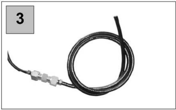
natural_image
Coiled black cable with metallic connectors, labeled '3' in top-left corner (no other text or symbols)
natural_image
Close-up of mechanical components including a black tool, a gray tool, and a white tool with a bracket (no text or symbols visible)
natural_image
Close-up of medical or laboratory equipment components including a surgical tool, connector, and connector (no visible text or symbols)

natural_image
Close-up of a medical or laboratory device with a black tool and connector, labeled '6' in the corner (no text or symbols on the device itself)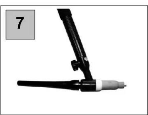
natural_image
Close-up of a black mechanical device with a white connector and a numbered label '7' in the corner (no text or symbols on the device itself)

that the following Appliance complies with the appropriate basic safety and health requirements of the EC Directive based on its design and type, as brought into circulation by us.
In a case of alternation of the machine, not agreed upon by us, this declaration will lose its validity.
Applicable EC Directives: - 2006/95/EC
Date/Authorized Signature:
!!! Please read this instruction for operation carefully before putting the machine into operation !!!
A.V. 2 Surplus print even in shortened version requires permission. Technical changes reserved. Illustrations used represent examples.
 | Do you have any technical questions? Claim? Do you need spare parts or instructions for operation? We are ready to help you quickly and without unnecessary bureaucracy at our site www.guede.com in the part Service. Please help us in helping you. In order to identify your machine in case of a claim we need its serial number, product number and year of production. All the data mentioned can be found at the type plate. Please write them down bellow to have them always handy: | ||
| Serial number: | Product number: | Year of production: | |
| Phone.: +49 (0) 79 04 / 700-360 | Fax: +49 (0) 79 04 / 700-51999 | E-Mail: support@ts.guede.com | |

Given unfavourable conditions in the power supply the equipment may cause the voltage to drop temporarily. If the supply impedance "Z" at the connection point to the public power supply exceeds 0,233 Ω EN 61000-3-11 it may be necessary to take further measures before the equipment can be used as intended from this power supply. If necessary, you can ask your local electricity supply company for the impedance value.
Warranty
A warranty period of 12 months applies to commercial use and 24 months apply to private use and commences on the day of purchase of the device.
Warranty applies exclusively to failures due to defective material or workmanship. An original sale slip with indication of date of sale must be presented in case of claiming for the warranty rights.
Warranty does not cover unprofessional use such as device overload, violent use, damage caused by third party or foreign materials, failure to comply with operations and assembly manual, and normal wear and tear.
Device
figure 1/8
| 1. | Welding | current | controller |
| 2. | Ground cable (-) | ||
| 3. | Electrode cable (+) | ||
| 4. | Main | switch |
Technical Data
Ordering No. 20055 INVERTOR 100 GC
| Supply voltage 230 V~50 Hz | |
| Mains power 3,2 kVA | |
| Minimum Protection 16 A | |
| Maximum welding current 100 A | |
| Idling voltage 85 V | |
| Recommended thickness of material 0,8-8 mm | |
| Electrodes 1,6-2,5 mm | |
| Range of control 10-100 A | |
| Switching time at maximum current 100A~15% / 55A~60% / 45 A~100% | |
| Protection class IP21S | |
| Approximate weight | 3,6 kg |
Ordering No. 20046 INVERTOR 140 GC
| Supply voltage 230V~50 Hz | |
| Mains capacity 4,7 kVA | |
| Minimum protection | 16 A |
| Idling voltage | 80 V |
| Recommended thickness of material | 0,8-12 mm / WIG 0,5-2mm |
| Electrodes | 1,6-4 mm |
| Range of control 20-140 A | |
| Start time at maximum current | 140 A~30% / 100 A~60 % / 90 A~100% |
| Insulation class | H |
| Protection class IP21S |
Approximate weight 6 kg
Ordering No. 20053 INVERTOR 160 GC
| Supply voltage 230 V~50 Hz | |
| Mains capacity 5,6 kVA | |
| Minimum protection 16 A | |
| Idling voltage 80 V | |
| Recommended thickness of material 0 | 8-15 mm / WIG 0,5-2 mm |
| Electrodes 1,6-4 mm | |
| Range of control 20-160 A | |
| Start time at maximum current 160 A~20 % / 100 A~60 % / 90 A~100 % | |
| Insulation class H | |
| Protection class IP21S | |
| Approximate weight 7 kg | |
General Safety Measures
It is essential to read the entire operation manual prior to the first use. If there are any doubts arising regarding connection and operation of the device, consult the manufacturer (servicing department).
Protect the device against moisture, rain and dust.
TO PROVIDE FOR MAXIMUM SAFETY, FOLLOW CAREFULLY THE INSTRUCTIONS BELOW:
The user shall be held liable for professionally done installation and for use of the machine in conformity with the manufacturer's data. If the user detects any electromagnetic faults, he is responsible for removing the same and use of the manufacturer's technical assistance. In many a case, just grounding the welding area is sufficient to remove the troubles. There are yet other cases, when developing an electromagnetic screen to cover the current source and the entire working area with a connected voltage filter may be helpful. In any case, the electromagnetic faults have to be removed so that they are not disturbing the user any more.
Caution: For the sake of safety, the current circuit should not be grounded. Any alteration of the grounding system should be done by competent authorised personnel able to estimate the consequences and risks of the alterations done.
Location Requirements
Prior to installation and starting the machine up, the user should account for any possible electromagnetic faults in the area.
The factors listed below should be taken into account:
a) other supply, control, signalling and telephone cables above the welding machine and under it and also in the adjacent area
b) radio and TV sets, receivers;
c) computers and other control equipments;
d) safety and monitoring instruments;
e) condition of health of those present, e.g. pacemakers, hearing aids etc.
f) meters used for calibrations;
g) protection of the other instruments and devices in the welding machine area. These devices should be compatible. Supplementary protection measures may be required.
h) Daytime, in which welding or other works are to be performed.
The area that may produce effects on the welding machine operation is subject to the building structure and other activities being carried out at a time of welding. The area may be as large as to near the neighbouring buildings.
Emission Reduction
Source Current Supply
As instructed by the manufacturer, the welding machine must be connected to the source current supply. If faults occur, it will be apparently necessary to provide for supplementary protective measures, such as a filter installed on the lead. The current leads of fixed welding machines should be protected with an insulation tube along the entire length of the cable. Welding cable should be as short as possible.
Special Safety Regulations
Introduction
The arc welding machines were developed thanks to many-year experience in the welding profession. Provided that the methods of operation prescribed by the manufacturer are provided, they will guarantee a high level of operating safety in addition to very good welding properties. For this reason, the management should take care to ensure that every person working with the machine has access to this information.
General Precautions
Protection against Burns
Sparkles, clinker, hot metal and radiation may be a serious hazard in arc welding putting eyes and skin at risk. The closer is the user or another person to the welding site, the bigger is the hazard they are exposed to. The user and any other persons working
adjacently to the welding site should wear adequate protective clothing and personal protective equipment. Protective gloves (special gloves for welding) and a headgear are indispensable. Goggles are essential and must be worn to protect the user's eyes against radiation, sparkles and hot metal.
Fire Protection
As hot metal, sparkles and clinker are generated by arc welding; precautions must be taken to prevent fire and explosions. Suitable fire extinguishers must be available in the area of welding site and any fire-hazardous materials should be removed from the area. The minimum distance of such materials from the welding area should be 10 metres (35 feet). Never weld empty tanks that contained toxics or explosives. Such tanks have to be cleaned very thoroughly before welding.
Never get down to welding if there are high concentrations of dust, easily inflammable gases and fire-hazardous vapours from liquids (such as petrol) in the atmosphere/air. Having completed the welding job, take care to cool down the welded parts before anybody could touch them or before they are in contact with fire-hazardous or ignitable materials.
Toxic Combustion Gases

Precautionary measures have to be taken for the welder or other persons not to be exposed to any toxic combustion products that may be generated by welding.
Certain chlorinated solvents decompose by action of ultraviolet radiation and forms phosgene. These solvents should be handled with care to prevent any contact with the welded parts. Containers with these solvents and/or other degreasing agents should be removed from the welding area.
If you are to weld metals with surface treatment layer containing lead, zinc, mercury and beryllium, remember that these ingredients may give formation to toxic combustion gases concentrations. The user should have adequate exhaust blowers hand or other special equipment – breathing apparatus or a helmet with air supply – to provide for fresh air supply.
Never weld metals containing surface treatment layer of materials forming toxic combustion gases. Exceptions are as follows:
• The surface layer was removed prior to welding. The welding area is sufficiently ventilated.
• The welder has the breathing apparatus with air supply available.
Radiation

UV radiation arising from welding may be harmful to the eyes and may cause burns of the skin. Therefore, protective clothing and a helmet should be worn.
Never wear contact lenses when welding because the strong glow may cause them sticking to the cornea.
The protective shield used at welding should have safety glass (DIN 10 as a minimum). If the glass gets damaged or cracked it should be replaced immediately.
Electrical arc may be detrimental to the eyes and it is harmful au to the distance of 15 metres (50 feet). Never look in the electrical arc with unprotected eyes.
Electrical Shock

Any electrical shock may be fatal. For this reason, never touch conductive cables and/or parts.
You will get isolated from the welded part by wearing insulation gloves and clothing. Parts of your clothing like gloves, boots, headgear and outerwear should be always dry. Avoid any work in moist or wet areas.
Do not touch the welded parts and do not hold them with your hand either; as soon as you feel the electrical shock, however small, stop welding immediately. Do not resume the work until an authorised person diagnoses and clear
the problem/fault. Frequent checks of the main cable for damages and cracks of the sheathing are essential and so is instant replacement of the damaged cables. Before the cable is replaced and the machine enclosure removed, disconnect the supply cable and main line. Never use the machine without respective housings and enclosures. Parts should be replaced with original spare parts only.
Never make changes to the safety circuit breaker, do not short circuit it and make sure that the current supply lead is equipped with an efficient grounding plug.
Provide for good grounding of the worktable for welding.
Only authorised personnel shall perform the maintenance. Mind the high risk related to the hazardous voltage is imminent at work with the machine.
Pacemakers

The persons with any electronic life-supporting apparatus (such as pacemaker) should consult a physician before getting exposed to the effects of welding machines - arc welding, cutting or burning or tack welding for them to be sure that the magnetic field combined with the high electric current values would not produce and damaging effects on their apparatuses.
Product Description and Specification
Introduction
The welding current supplies series 80 A will supply constant current and they are designed in an INVERTER technique, equipped with heavy-duty and reliable components and may be used for bar electrodes and for protective atmosphere tungsten electrode welding.
System Description
The current input and the control logic equipment is mounted on a single main panels in form of special hybrid plates they may be easily interchanged. A high degree of reliability is this added and the maintenance and servicing is simplified. The power module
includes INVERTER working at frequency above 80 kHz and a very low resonance time (500 milliseconds). The result of this equipment is very even welding and simple start, homogenous-sized drops and better weld penetration.
Technical Symbols Glossary
EN 60974 International standards
Seriennummer Series Number – please quote with any inquiries MMA good for sheathed electrode welding
WIG good for protective atmosphere tungsten electrode welding
U. secondary ignition voltage X Start time - percentage rate
Start time shows the percentage rate out of 10 minutes, within which the current input at a given current value is without overheating.
I Welding current
U Secondary voltage with welding current 12
U1 Rated mains voltage
1\~50/60Hz Single-phase supply 50 or 60 Hz
I1 Absorbed current with respective welding current 12. When the current for welding is supplied by the tungsten electrode in protective atmosphere divide the value of I1 by 1.6
IP21 Metal frame protection class
S Good for work in high-hazardous areas
The appliance meets the EN 60974-10, class A requirements. That means it can only be used for industrial purposes. In unfavourable conditions, the appliance can cause electromagnetic disturbance.
Thermal Protection
Overheat Protection and Protection against Principal Current Supply Fault
The current supply will turn off in result of intervention of the mains voltage control equipment and in result of overheating (thermal switch on cooling elements).
Installation
Unpacking and Installation
Unpack the machine and inspect it thoroughly to see whether it was not damaged at transport. The claims for damages, if any, should set up with the carrier. For you not to lose the right for damages, do not sign any blank documents or you may state in a note that you reserve the right to claim damages for case that after unpacking damages inflicted by transport are revealed.
Any notices regarding the machine should quote the model and the series number to be found on the current input rear side. Having unpacked, install the machine in a well-ventilated area free of any dust, if possible. Take care to prevent blocking the air supply next to the cooling slots.
Warning: It is essential not to restrict the air supply around the machine as that might result in overheating and subsequently damaging some of the inside components.
A minimum of 200 mm of free space should be preserved around the machine. Do not put filters and covers in front of ventilation opening, the warranty-based claims would become void.
Note: If you carry the machine on your shoulder, take care not to block the ventilation openings.
Installation
Only experienced personnel should install the machine. Any connections have to be in compliance with effective rules and in full conformity with safety regulations (CENELEC HD 427).
General Notes
Prior to using this current supply, read carefully CENELEC HD 407 and HD 433 standards. Insulation cables, electrode holding clips, plugs and sockets should be checked to see whether length and cross sections of welding cables correspond to the selected current:
Cable length up to 5 m : minimum cross section 16 mm ^2
Cable length 5 - 20 m : minimum cross section 25 mm ^2
Cable length 20 - 30 m : minimum cross section 35 mm ^2
Start up
Control Panel Description
Following elements are placed on the control panel:
-
Current control knob
-
Electrodes and grounding terminals cable connections
- Welding current indicating LED (OK if on)
- Normally, yellow LED is off. When it goes on, it may signal following faults:
•Mains voltage different by more than ± 10%.
• Welding machine overloaded.
Sheathed Electrode Welding
The welding machine can be used with any electrodes, the cellulose electrodes (AWS 6010) included. Use electrode-holding clips without any protruding lock screws in compliance with the current safety standards. Make sure that the main switch on the rear side is in position,,0" or the main supply cable is not plugged in. Connect the welding cables to their polarity and in conformity with the electrode manufacturer's data. Welding current circuit should avoid any direct or indirect contact with the protective cable, except for contact on the welded piece.
If grounding is deliberately done using the protective cable on the welded piece, the connection has to be as short as possible. The protective cable cross-section has to be equal to that of the reverse welding cable as a minimum. Both the cables should be connected to the welding piece at the same point. Use the grounding terminal on the machine or a grounding terminal nearby. Any precautionary measures should be taken to prevent stray currents. Check that the mains voltage is corresponding to the machine input voltage.
Main supply cable connection: When mounting the plug, care has to be taken to have the corresponding capacity and the main cable yellow-green conductor being connected to the grounding plug. The capacity of thermal magnetic switch or fuses of the main supply line should be more or equal to the machine-absorbed current I1.
The absorbed current I1 may be determined upon having read all the technical specifications on the machine according to main input voltage U1. The cross section of any extension cables should correspond to the absorbed current I1. The current supply shall be switched on using the main switch on the machine rear side.
WARNING: ELECTRIC SHOCKS MAY BE FATAL!
DO NOT TOUCH ANY CONDUCTIVE PARTS!
DO NOT TOUCH ANY WELDING CONNECTION OUTLETS WHEN THE MACHINE IS ON!
NEVER TOUCH THE WELDING MACHINE OR ELECTRODE AND THE
GOUND TERMINAL AT A TIME!
Select the current subject to the electrode diameter, welding position and the welding seam. With welding completed, keep in mind that the main switch has to be turned off and the electrode removed from the holder.
Welding with WIG equipment (for tungsten welding in protective atmosphere): ordering no. Güde 41690.
Caution! It is not possible with ordering no. 20045, 20054!
Before getting down to work, make sure that the right gas is available.
Fe || steel || ArCO2
Al aluminium Ar (not possible with this device)
V2A premium steel ArO2
Connecting the device, proceed as described below:
- Connect the gas hose to the gas fitting on the corresponding bottle using a clip and connect to the WIG equipment.
- The WIG equipment plug connects to the corresponding socket „Dinse“ on the inverter (negative pole).
Caution: At WIG-welding (using a tungsten electrode in protection atmosphere), the grounding cable is the positive pole and the WIG package is the negative pole.
- Now, plug the grounding cable in a corresponding socket (positive pole).
- Sharpen the tungsten needle in perpendicular direction to the grinding wheel and insert it in the clamp. Ca 5 mm of the tungsten needle should protrude from the ceramic nozzle in the front. (see Fig. 1-4).
- Now, turn the burner gas valve on (ca ¼ turn) and switch the device on WIG (if available)
- Lighting: Now, set the ceramic nozzle edge sideward to the material and swing the needle close the material until the electric arc is formed.
→ Practice makes perfect!
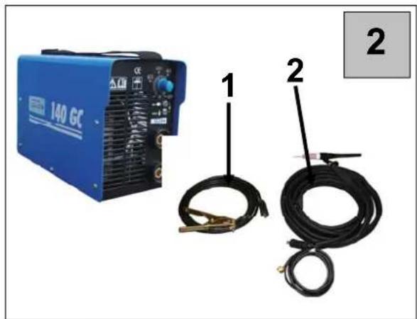
figure 2
-
Electrode cable (+)
-
Ground cable (-)
figure 3
Hose with adapter
that the following Appliance complies with the appropriate basic safety and health requirements of the EC Directive based on its design and type, as brought into circulation by us.
In a case of alternation of the machine, not agreed upon by us, this declaration will lose its validity.
Applicable EC Directives: - 2006/95/EC
Date/Authorized Signature:
that the following Appliance complies with the appropriate basic safety and health requirements of the EC Directive based on its design and type, as brought into circulation by us.
In a case of alternation of the machine, not agreed upon by us, this declaration will lose its validity.
Directives CE applicables : - 2004/108/EC Applicable EC Directives: - 2006/95/EC
Normes harmonisées applicables: - EN 60974-1:2005 Applicable harmonized - EN 60974-10:2007 Standard:
Date/Authorized Signature:
Autorisé à signer:
Title of Signatory:
M. Arnold, Manager
Documentation technique: J. Bürkle; FBL, QS
CZ
that the following Appliance complies with the appropriate basic safety and health requirements of the EC Directive based on its design and type, as brought into circulation by us.
In a case of alternation of the machine, not agreed upon by us, this declaration will lose its validity.
Applicable EC Directives: - 2006/95/EC
Date/Authorized Signature:
Údaje o podepsaném: pan Arnold, jednatel
Title of Signatory:
that the following Appliance complies with the appropriate basic safety and health requirements of the EC Directive based on its design and type, as brought into circulation by us.
In a case of alternation of the machine, not agreed upon by us, this declaration will lose its validity.
Applicable EC Directives: - 2006/95/EC
Applicable harmonized
Standard:

Date/Authorized Signature:
Údaje o podpísanom:
Title of Signatory:
pán Arnold, konatel'
that the following Appliance complies with the appropriate basic safety and health requirements of the EC Directive based on its design and type, as brought into circulation by us.
In a case of alternation of the machine, not agreed upon by us, this declaration will lose its validity.
Applicable EC Directives: - 2006/95/EC
Date/Authorized Signature:
EC Declaration of Conformity
that the following Appliance complies with the appropriate basic safety and health requirements of the EC Directive based on its design and type, as brought into circulation by us.
In a case of alternation of the machine, not agreed upon by us, this declaration will lose its validity.
Applicable EC directives: - 2006/95/EC
Standard normativi in merito
Date/Authorized Signature:
that the following Appliance complies with the appropriate basic safety and health requirements of the EC Directive based on its design and type, as brought into circulation by us.
In a case of alternation of the machine, not agreed upon by us, this declaration will lose its validity.
Applicable EC Directives: - 2006/95/EC
Date/Authorized Signature:
EC Declaration of Conformity
Temeljem ove izjave, mi, Güde GmbH & Co. KG
We herewith declare, Birkichstraße 6, 74549 Wolpertshausen, Germany
proglašavamo da dole navedeni uređaji, u pogledu njihove koncepcije i konstrukcije kao i u pogledu izvedbi koje smo uveli u promet, ispunjavaju odgovarajuće osnovne zahtjeve u vezi sigurnosti i zdravlja prema smjernicama EU.
that the following Appliance complies with the appropriate basic safety and health requirements of the EC Directive based on its design and type, as brought into circulation by us.
In a case of alternation of the machine, not agreed upon by us, this declaration will lose its validity.
Oznaka uređaja: - 100 GC, 140 GC, 160 GC
Machine Description:
Nar. broj: - 20055, 20046, 20047
Article-No.:
Applicable EC Directives:
2006/95/EC
Primijenjene harmonizirane
norme: - EN 60974-1:2005
Applicable harmonized - EN 60974-10:2007
Standards:
Date/Authorized Signature:
21.06.2011
Podaci o potpisanoj osobi gospodin Arnold, Direktor
Title of Signatory:
Tehnička dokumentacija: J. Bürkle; FBL, QS
SLO
that the following Appliance complies with the appropriate basic safety and health requirements of the EC Directive based on its design and type, as brought into circulation by us.
V primeru spremembe naprave, o kateri se niste posvetovali z nami, ta izjava izgubi svojo veljavnost.
In a case of alternation of the machine, not agreed upon by us, this declaration will loose ist validity.
Applicable EC Directives: - 2006/95/EC
Date/Authorized Signature:
that the following Appliance complies with the appropriate basic safety and health requirements of the EC Directive based on its design and type, as brought into circulation by us.
In a case of alternation of the machine, not agreed upon by us, this declaration will lose its validity.
Applicable EC Directives: - 2006/95/EC
Date/Authorized Signature:
We herewith declare,
Birkichstraße 6, 74549 Wolpertshausen, Germany
proglašavamo, da dole navedeni uređaji, u pogledu njihove koncepcije i konstrukcije kao i u pogledu izvedbi koje smo uveli u promet, ispunjavaju odgovarajuće osnovne direktive bezbjednosti i zdravlja prema smjernicama EU.
that the following Appliance complies with the appropriate basic safety and health requirements of the EC Directive based on its design and type, as brought into circulation by us.
Ako dođe do promjena na uređaju bez naše suglasnosti, ova Izjava postaje nevažećom.
In a case of alternation of the machine, not agreed upon by us, this declaration will lose its validity.
Oznaka uređaja: - 100 GC, 140 GC, 160 GC
Applicable EC Directives: - 2006/95/EC
Primijenjene harmonizirane
norme:
- EN 60974- 1:2005
Applicable harmonized
- EN 60974-10:2007
Standard

that the following Appliance complies with the appropriate basic safety and health requirements of the EC Directive based on its design and type, as brought into circulation by us.
In a case of alternation of the machine, not agreed upon by us, this declaration will lose its validity.
Applicable EC Directives: - 2006/95/EC
Kullanılan uyum
Date/Authorized Signature:




- Warranty
- Device
- General Safety Measures
- Protect the device against moisture, rain and dust.
- TO PROVIDE FOR MAXIMUM SAFETY, FOLLOW CAREFULLY THE INSTRUCTIONS BELOW:
- Location Requirements
- Emission Reduction
- Special Safety Regulations
- Introduction
- General Precautions
- Protection against Burns
- Fire Protection
- Toxic Combustion Gases
- Radiation
- Electrical Shock
- Pacemakers
- Product Description and Specification
- System Description
- Technical Symbols Glossary
- Thermal Protection
- Overheat Protection and Protection against Principal Current Supply Fault
- Installation
- Unpacking and Installation
- General Notes
- Start up
- Control Panel Description
- Sheathed Electrode Welding
- figure 2
- figure 3
- EC Declaration of Conformity
Brand : GUDE
Model : 20046
Category : Welding machine