
TVIP41660 - Surveillance Camera ABUS - Free user manual and instructions
Find the device manual for free TVIP41660 ABUS in PDF.


| Product type | IP surveillance camera |
| Brand | Abus |
| Model | TVIP41660 |
| Resolution | Full HD (1920 x 1080 pixels) |
| Sensor | CMOS 1/2.7", 2 MP |
| Night vision | Yes, infrared LED up to 30 meters |
| Viewing angle | 90° (horizontal) |
| Power supply | PoE (Power over Ethernet) or 12 V DC adapter (not included) |
| Connectivity | Ethernet RJ45 10/100 |
| Storage | microSD card slot (max. 128 GB) or recording on NVR |
| Dimensions | Approximately 70 x 70 x 180 mm |
| Weight | Approximately 500 g |
| Protection rating | IP66 (weather-resistant) |
| Main features | Motion detection, push notification, night vision, two-way audio |
| Care and cleaning | Clean the lens with a soft, dry cloth; avoid harsh solvents |
| Security | Data encryption, administrator password access, firmware update |
| Spare parts and repairability | Power adapter, Ethernet cable, mounting kit; repair possible by a professional |
| General information | 2-year warranty, compatible with video management systems (NVR) |
Frequently Asked Questions - TVIP41660 ABUS
User questions about TVIP41660 ABUS
0 question about this device. Answer the ones you know or ask your own.
Ask a new question about this device
Download the instructions for your Surveillance Camera in PDF format for free! Find your manual TVIP41660 - ABUS and take your electronic device back in hand. On this page are published all the documents necessary for the use of your device. TVIP41660 by ABUS.
USER MANUAL TVIP41660 ABUS
natural_image
Exterior view of a white autonomous security camera with a spherical lens (no text or symbols visible)D Bedienungsanleitung
GB User guide
F Notice d'utilisation
NL Gebruikershandleiding
DK Betjeningsvejledning
PL Instrukcja obsługi
RUS Инструкция по эксплуатации
E Manual de instrucciones
① Istruzioni per l'uso
s Bruksanvisning
| D | Diese Bedienungsanleitung enthält wichtige Hinweise zur Inbetriebnahme und Handhabung.Achten Sie hierauf, auch wenn Sie dieses Produkt an Dritte weitergeben.Heben Sie deshalb diese Bedienungsanleitung zum Nachlesen auf!Eine Auflistung der Inhalte finden Sie im Inhaltsverzeichnis mit Angabe der entsprechenden Seitenzahlen auf Seite 7. | PL | Niniejsza instrukcja obsługi zawiera ważne wskazówki dotyczące uruchamiania i obsługi.Pamiętaj o tym, także przekazując produkt osobie trzeciej. Zachowaj instrukcję do wykorzystania w przyszłości!Wykaz treści znajdziesz w spisie treści z podaniem odpowiednich liczb stron na stronie373. |
| GB | This user guide contains important information on starting operation and using the device.Make sure that this user guide is handed over when the product is given to other persons.Keep this user guide to consult later.A list of contents with the corresponding page number can be found in the index on page 80. | RUS | Данная инструкция по эксплуатации содержит важные указания по вводу в эксплуатацию и обращению с продуктом.Примите это во внимание, также при передаче продукта в пользование третьим лицам.По этой причине сохраните данную инструкцию для повторного прочтения!Вся информация отражена в Содержании с указанием соответствующих номеров страниц на Странице 446. |
| F | Les recommandations contenues dans cette notice d'utilisation sont importantes pour la mise en service et l'utilisation du produit.Nous vous prions de bien vouloir les respecter. Si vous étiez amené à revendre le produit, nous vous prions de bien vouloir transmettre cette notice au nouvel acquéreur.Nous vous recommandons également de conserver cette notice d'utilisation afin de pouvoir la consulter à tout moment.Vous trouverez le récapitulatif des indications du contenu á la table des matières avec mention de la page correspondante á la page 153. | E | Este manual de instrucciones contiene indicaciones importantes para la puesta en funcionamiento y para la utilización.Tenga esto en cuenta, también cuando transfiera este aparato a terceras personas.Por este motivo, guarde este manual para poder consultarlo cuando lo necesite.El listado de los contenidos figura en el índice junto a las páginas correspondientes en la página 519. |
| NL | Deze gebruiksaanwijzing hoort bij dit product.Er staan belagrijke aanwijzingen in betreffende ingebruikname en gebruik, ook als u dit product doorgeeft aan derden. Bewaar deze hendeiding zorgvuldig, zodat u deze later nog eens kunt nalezen!U vindt een opsomming van de inhoud in de inhoudsopgave met aanduiding van de paginanummers op pagina 227. | I | Le presenti istruzioni per l'uso contengono note importanti sulla messa in funzione e sull'utilizzo.Vanno osservate anche in caso di cessione del prodotto a terzi.La preghiamo pertanto di conservare le presenti istruzioni per l'uso in vista di una consultazione futura.Un elenco dei contenuti con l'indicazione delle pagine corrispondenti è riportato nell'indice a pagina 592. |
| OK | Denne manual hører sammen med dette produkt. Den indeholder vigtig information som skal bruges under opsætning og efterfølgende ved service. Dette skal huskes også når produkter gives videre til anden part.Læs derfor denne manual grundigt igennem også for fremtiden.Indholdet kan ses med sideanvisninger kan findesi indekset på side 300. | S | Denna bruksanvisning innehåller viktiga anvisningar för idrifttagande och användning.Dessa anvisningar ska observerad även om denna produkt överlämnas till tredje part.Förvara denna bruksanvisning för framtida referens!På sidan 666 finns finns en innehållsförteckning med sidoreferenser. |
TVIP41660

natural_image
Exterior view of a white autonomous security camera (ABUS) with a spherical lens, shown against a plain background.Bedienungsanleitung
natural_image
Line drawing of a security camera with label 'ANUS' on top (no other text or symbols)WLAN HD 720p Schwenk-/Neige-/Zoom Innen Dome Kamera

natural_image
Line drawing of a coiled spring device with no text or symbols on the device itself
natural_image
Line drawing of a flexible network cable with connectors (no text or symbols)natural_image
Diagram of ceiling-mounted screw arrangement with upward arrows indicating direction (no text or symbols)
natural_image
Illustration of a hand using a power tool to test a device on a laptop screen (no text or symbols present)natural_image
Line drawing of a hand inserting a USB into a network device connected to a laptop (no text or symbols present)Konto-Informationen hinterlegen:
DynDNS.com

Links: niedrige Empfindlichkeit.
Aktivierungszeit
natural_image
Exterior view of a white autonomous security camera (ABUS) with a spherical lens, shown against a plain background.User manual
You can find important information and FAQs about this and other products online at:
www.abus.com
Introduction
Dear Customer,
Thank you for purchasing this product.
This device complies with the requirements of the applicable EU directives. The declaration of conformity can be obtained from:
To ensure this condition is maintained and that safe operation is guaranteed, it is your obligation to observe this user manual.
Read the entire user manual carefully before putting the product into operation and pay attention to all operating instructions and safety information!
All company names and product descriptions are trademarks of the corresponding owner. All rights reserved.
If you have any questions, please contact your specialist installation contractor or specialist dealer.

Data storage is subject to national data privacy guidelines.

Warning as required by §201 StGB (German Criminal Code):
Whosoever unlawfully makes an audio recording of the privately spoken words of another, and uses or makes a recording thus produced accessible to a third party, shall be liable to imprisonment or a fine. Whosoever unlawfully overhears with an eavesdropping device the privately spoken words of another not intended for his attention, or publicly communicates, verbatim or the essential content of, the privately spoken words of another, recorded or overheard, shall incur the same penalty.

Disclaimer
This user manual has been produced with the greatest of care. Should you discover any omissions or inaccuracies, please contact us in writing at the address provided above.
ABUS Security-Center GmbH does not accept any liability for technical and typographical errors, and reserves the right to make changes to the product and user manuals at any time and without prior warning.
ABUS Security-Center GmbH is not liable or responsible for direct or indirect damage resulting from the equipment, performance and use of this product. No forms of guarantee are assumed for the contents of this document.
Explanation of symbols
 | The triangular high voltage symbol is used to warn of the risk of injury or health hazards (e.g. caused by electric shock). |
 | The triangular warning symbol indicates important notes in this user manual which must be observed. |
 | This symbol indicates special tips and notes on operating the unit. |
Important safety information
 | All guarantee claims are invalid in the event of damage caused by non-compliance with this user manual. We cannot be held liable for resulting damage. |
 | In the event of material or personal damage caused by improper operation or non-compliance with the safety information, we cannot be held liable. All guarantee claims are void in such cases. |
The following safety information and hazard notes are not only intended to protect your health, but also to protect the device from damage. Please read the following points carefully:
- There are no components inside the product that require servicing. Dismantling the product invalidates the CE certification and the guarantee/warranty.
• The product may be damaged if it is dropped, even from a low height. - Install the device so that the image sensor is not exposed to direct sunlight. Pay attention to the installation instructions in the corresponding section of this user manual.
- The device is designed for indoor use.
Avoid the following adverse conditions during operation:
- Moisture or excess humidity
• Extreme heat or cold - Direct sunlight
- Dust or flammable gases, vapours or solvents
- Strong vibrations
• Strong magnetic fields (e.g. next to machines or loudspeakers) - The camera must not be installed on unstable surfaces.
General safety information:
- Do not leave packaging material lying around. Plastic bags, sheeting, polystyrene packaging, etc. can pose a danger to children if played with.
- The video surveillance camera contains small parts which could be swallowed and must be kept out of the reach of children for safety reasons.
- Do not insert any objects into the device through the openings.
- Only use replacement devices and accessories that are approved by the manufacturer. Do not connect any non-compatible products.
- Please pay attention to the safety information and user manuals for the other connected devices.
- Check the device for damage before putting it into operation. Do not put the device into operation if you identify any damage!
- Adhere to the normal voltage limits specified in the technical data. Higher voltages could destroy the device and pose a health risk (electric shock).
Safety information
-
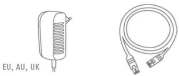
Power supply: Power supply unit 100–240 V AC, 50/60 Hz / 12 V DC, 1 A (included in the scope of delivery).
Only operate this device through a power source which supplies the mains power specified on the type plate. If you are unsure of the available power supply, contact your utility company.
Disconnect the device from the power supply before carrying out maintenance or installation work. -
Overloading
Avoid overloading electrical sockets, extension cables and adapters, as this can result in fire or electric shock.
- Cleaning
Only use a damp cloth to clean the device. Do not use corrosive cleaning materials.
Disconnect the device from the power supply before cleaning.
Warnings
Observe all safety and operating instructions before putting the device into operation for the first time.
-
Observe the following information to avoid damage to the power cable and plug:
-
Do not modify or manipulate the power cable or plug.
- Do not bend or twist the power cable.
- Do not pull the cable when disconnecting the device from the power – always take hold of the plug.
-
Ensure that the power cable is positioned as far away as possible from any heating equipment, as this could otherwise melt the plastic coating.
-
Follow these instructions. Non-compliance with these instructions could lead to electric shock:
-
Never open the housing or power supply unit.
-
Do not insert any metallic or flammable objects into the device.
• Use surge protection to prevent damage caused by overvoltage (e.g. in electrical storms). -
Disconnect defective devices from the power immediately and contact your specialist dealer.
| When installing the device in an existing video surveillance system, ensure that all devices have been disconnected from the mains power circuit and low-voltage circuit. | |
| If in doubt, have a specialist technician carry out assembly, installation and connection of the device. Improper or unprofessional work on the power supply system or domestic installations puts both you and others at risk.Connect the installations so that the mains power circuit and low-voltage circuit always run separately from each other. They should not be connected at any point or become connected as a result of a malfunction. |
Unpacking the device
Handle the device with extreme care when unpacking it.
| If the original packaging has been damaged, you must start by inspecting the device. If the device shows signs of damage, return it in the original packaging and inform the delivery service. |
Contents
- Intended use....82
- Scope of delivery 82
- Features and functions 82
- Camera description 83
- Description of the connections 84
- Mounting/installation....85
6.1. Mounting the camera....85
6.2. Orientation of the camera 85
- Initial start-up 86
- Accessing the network camera for the first time.... 87
- Password prompt....88
- User functions....89
10.1. Menu bar....89
10.2. Live image display 90
10.3. Audio/video control 90
10.4. Camera control 91
10.4.1. PTZ control 91
10.4.2. Preset settings 91
- Playback 92
- Configuration 93
12.1. Local Configuration....93
12.2. Basic Configuration....95
12.3. Advanced configuration 96
12.3.1. System 96
12.3.1.1. Device Information....97
12.3.1.2. Time Settings....98
12.3.1.3. Maintenance 99
12.3.1.4.DST 100
12.3.2. Network.... 101
12.3.2.1. TCP/IP 102
12.3.2.2. Port 104
12.3.2.3. DDNS.... 105
12.3.2.5.Wi-Fi 108
12.3.2.6. UPnP™ 110
12.3.3. Video/Audio 111
12.3.3.1. Video.... 112
12.3.3.2. Audio.... 113
12.3.4. PTZ 114
12.3.4.1. Basic 115
12.3.4.2. Initial Position.... 116
12.3.4.3. Scheduled Tasks 117
12.3.4.4. Clear configuration 119
12.3.5. Image.... 120
12.3.5.1. Display Settings 121
12.3.5.2. OSD Settings 124
12.3.5.3.Text Overlay 125
12.3.5.4. Privacy Mask 126
12.3.6. Security 127
12.3.6.1.User 128
12.3.6.2. IP Address Filter 129
12.3.7. Basic Event.... 130
12.3.7.1. Motion detection 131
12.3.7.3. Alarm Input 133
12.3.7.4. Alarm Output.... 135
12.3.7.5. Email.... 137
12.3.7.6. Snapshot.... 139
12.3.8. Storage 141
12.3.8.2. Recording plan.... 142
12.3.8.3. Storage Management.... 144
- Log 145
- Maintenance and cleaning.... 146
14.1. Maintenance 146
14.2. Cleaning.... 146
- Disposal 146
- Disposal 146
- Technical data 147
- GPL license information 148
1. Intended use
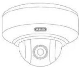
With a detailed high resolution of 1280 x 720 pixels, the TVIP41660 WLAN HD 720p pan/tilt/zoom indoor dome camera records 25 frames per second. The PTZ camera (PTZ refers to the functions pan, tilt and zoom) has a triple optical and 16-times digital zoom, meaning that even distant image sections can be viewed up-close to enable exact person recognition.
Thanks to PoE (Power over Ethernet), it is possible to power the camera using the network cable, with no additional cables required.
The WPS button is used to facilitate setting up the WLAN connection. An external sounder, such as a siren, can also be easily controlled via an alarm output.
2. Scope of delivery
natural_image
Line drawing of a mechanical component labeled 'ABUS' (no additional text or symbols)WLAN HD 720p pan/tilt/zoom indoor dome camera
natural_image
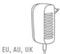
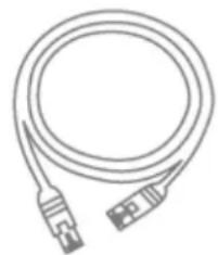
Line drawings of two electronic devices: a cylindrical capacitor labeled 'EU, AU, UK' and a coiled cable with connectors (no text or symbols on the devices themselves)PSU 1 m network cable

Ceiling bracket CD

Quick start guide

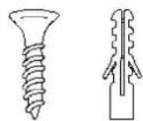
Installation material
3. Features and functions
• Detailed high resolution (1280 x 720 pixels at 25 frames per second)
• 3x optical and 16x digital zoom for detailed images
- Web and mobile access to live images and panning, tilting and zooming using the IPCam app or a browser
- Integrated microSD card slot for internal data storage, which functions as a back up solution
- With WDR function for backlight compensation – ideal for entrance areas
- Integrated motion sensor system
- With alarm output for controlling an external sounder (e.g. siren, light)
• WPS button for easy set-up of the WLAN connection
- PoE (Power over Ethernet) compatible
4. Camera description
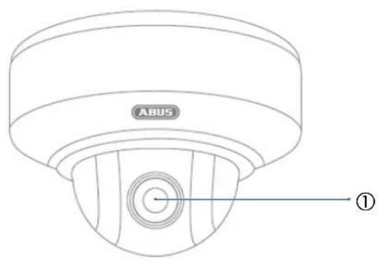
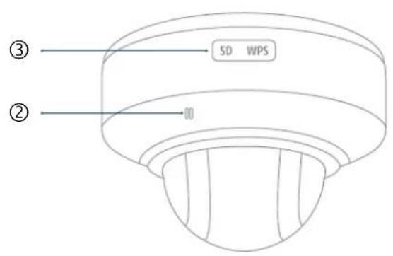
| No | Description |
| 1 | Lens |
| 2 | Microphone |
| 3 | WPS button & microSD card slot |
5. Description of the connections

①
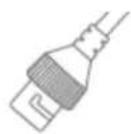
②

③
| No | Description |
| 1 | Power supply 12 V DC(Round plug 5.5 x 2.1 mm) |
| 2 | Network access (RJ45)The network access includes a cover, which can be used if necessary. This cover provides additional protection for the plug-in connector. When using the cover, the network cable must only be connected (crimped) to the network plug once it has been passed through the cover. In addition, the connections (as well as the power supply connection) can be sealed with insulation tape. |
| 3 | Breakout cableYellow/red Alarm inputYellow/green Alarm outputYellow/black GroundWhite Audio inputPink Audio outputBlack Ground audio Use the following wires for the different connection options.Alarm input connection: Alarm input & GroundAlarm output connection: Alarm output & GroundAudio input connection: Audio input & Ground audioAudio output connection: Audio output & Ground audio Use the following wires for the different connection options.Alarm input connection: Alarm input & GroundAlarm output connection: Alarm output & GroundAudio input connection: Audio input & Ground audioAudio output connection: Audio output & Ground audio |
6. Mounting/installation
6.1. Mounting the camera

IMPORTANT!
The camera must be disconnected from the power supply during installation.
Use the accompanying drilling template or mount for drilling the mounting holes.
Drill the holes in advance and insert the accompanying screw anchor.
Use the accompanying screws to fasten the ceiling bracket in place.
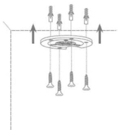
natural_image
Diagram of ceiling-mounted screw arrangement with upward arrows indicating direction (no text or symbols)
Please note that the arrow and the label "FRONT" on the ceiling bracket points in the right direction.
6.2. Orientation of the camera
Then place the camera onto the ceiling bracket and latch the camera in place by rotating it anticlockwise.
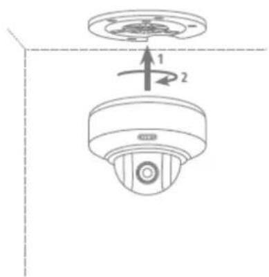
7. Initial start-up
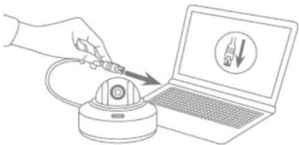
The network camera automatically detects whether a direct connection between the PC and camera should be established. A crossover network cable is not required for this. You can use the supplied patch cable for direct connection for initial start-up.
Connecting the network camera directly to a PC/laptop
- Ensure that a CAT 5 network cable is used.
- Connect the cable to the Ethernet interface of the PC/laptop and the network camera
- Connect the network camera to the power supply.
- Configure the network interface of your PC/laptop to the IP address 192.168.0.2 and the default gateway to 192.168.0.1.
- Proceed to point 8 to finish the initial set-up and establish the connection to the network camera.
natural_image
Illustration of a hand using a power tool to test a device on a laptop screen (no text or symbols present)Connecting the network camera to a router/switch
- Ensure that a CAT 5 network cable is used for the connection.
- Connect the PC/laptop to the router/switch.
- Connect the network camera to the router/switch.
- Connect the network camera to the power supply.
- If a DHCP server is available on your network, set the network interface of your PC/laptop to "Obtain an IP address automatically".
- If no DHCP server is available, configure the network interface of your PC/laptop to 192.168.0.2 and the default gateway to 192.168.0.1.
- Proceed to point 8 to finish the initial set-up and establish the connection to the network camera.

natural_image
Illustration of a hand using a power tool to test a device on a laptop screen (no text or symbols present)8. Accessing the network camera for the first time
The network camera is accessed for the first time using the ABUS IP Installer.
After the installation wizard is started, it searches for all connected ABUS network cameras and video servers on your network.
You can find the program on the CD-ROM included. Install the program on your PC and then run it.
If a DHCP server is available on your network, the IP address is assigned automatically for both the PC/laptop and the network camera.
If no DHCP server is available, the network camera automatically sets the following IP address: 192.168.0.100.
Your PC system must be located in the same IP subnetwork to establish communication with the network camera (PC IP address: e.g. 192.168.0.2).


The default setting for the network camera is "DHCP". If no DHCP server is in operation on your network, we recommend setting the IP address manually to a fixed value following initial access to the network camera.
9. Password prompt
An administrator password is defined for the network camera prior to delivery. For reasons of security, however, the administrator should select a new password immediately. After this administrator password has been saved, the network camera asks for the user name and password every time it is accessed.
The administrator account is set up in the factory as follows: user name "admin" and password "12345". Each time the network camera is accessed the browser displays an authentication window and asks for the user name and password. Should your individual settings for the administrator account no longer be accessible, please contact our technical support team.
To enter a user name and password, proceed as follows:
Open Internet Explorer and enter the camera's IP address (e.g. 'http://192.168.0.100').
You will then be presented with the following authentication prompt:

-> You are now connected to the network camera and can already see a video stream.
10. User functions
Open the network camera home page. The interface is divided into the following main areas:
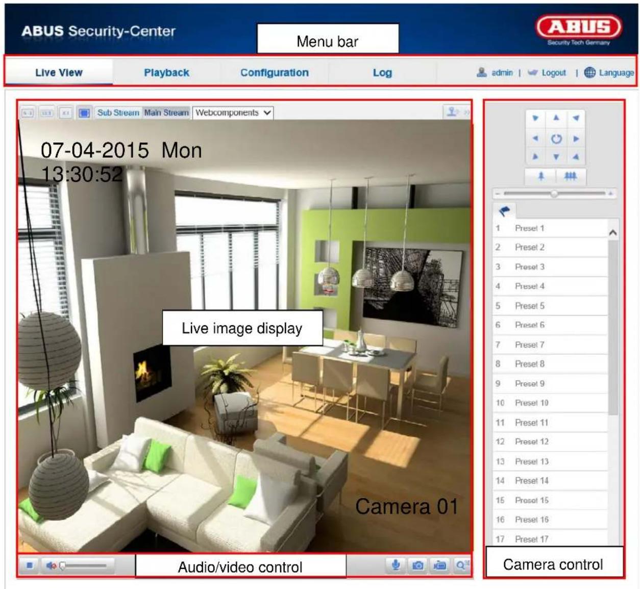
10.1. Menu bar
Make a selection by clicking on the appropriate tab: "Live View", "Playback", "Configuration" or "Log".
| Button Description | |
| admin | Display of the user logged on |
| Logout | User logout |
| Language | Selection of the desired language |
10.2. Live image display
You can access the full-screen view by double-clicking.
| Button Description | |
 | Activate 4:3 view |
 | Activate 16:9 view |
 | Display original size |
 | Automatically adjust view to browser |
| Sub-Stream Main Stream | Selection of the streaming type for the live view |
10.3. Audio/video control
| Button | Description |
 | Disable live view |
 | Enable live view |
 | Disable/enable audio, adjust volume |
 | Microphone on/off, If the microphone is activated, then two-way communication from the PC to the camera is possible. (Audio output on the camera) |
 | Instant image (snapshot) |
 | Start/stop manual recording |
 | Digital zoom on/off |
 | Start/stop 3D zoom |
10.4. Camera control
10.4.1. PTZ control
To display the PTZ control, click on the field in the live view.

| Button Description | |
 | Arrow buttons:Control the pan and tilt movements |
 | Zoom in/outPress the button to increase the zoom and the button to decrease the zoom. |
 | Adjust the PTZ speed |
 | Call up the initial position (not available) |
10.4.2. Preset settings
Select the Preset tab to be able to call up, set and delete up to 16 preset positions. Use the PTZ control buttons to select the desired position.
Click on the button to create the preset.
| Button Description | |
 | Select the desired preset position. The selected position has a blue background |
 | Call up the position |
| [H0KB] | Create the position |
 | Delete the position |
11. Playback

In playback, you can play back data that is recorded on the microSD card. Select the desired day in the calendar and click "Search".
The recordings for the selected day are shown in the timeline. The coloured labelling indicate the nature of the event that triggered the recording.
You can set the time of the desired recording under playback time.
12. Configuration
12.1. Local Configuration
Under the "Local Configuration" menu item, you can select settings for file paths of the recordings and snapshots.
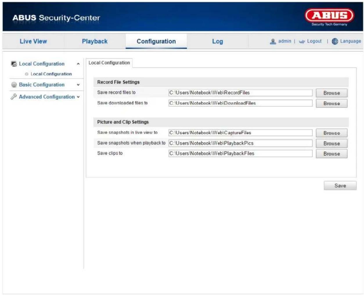
Record File Settings
You can define the file size for recordings, the recording path and the path for downloaded files here. To apply the changes, click "Save".
Save record files to
You can determine the file path that is to be used for manual recordings here. The default path used is C:\
Save downloaded files to
You can store the file path for downloaded videos here.
The following path is set by default: C:\
Image and Clip Settings
Here you can store the path for instant images, snapshots taken during playback as well as for edited videos.
Save snapshots in live view to
Select the file path for instant images from the live view.
The following path is set by default: C:\
Save snapshots during playback to
You can store the path here for saving snapshots taken during playback.
The following path is set by default: C:\
Save clips to
You can specify the save path for storing edited video clips here.
The following path is set by default: C:\
12.2. Basic Configuration
All settings located under "Basic Configuration" can also be found under the menu item "Advanced Configuration". Please note the "Available in mode" column in the descriptions of the "Advanced Configuration".

12.3. Advanced configuration
12.3.1. System
| Menu item | Description | Available in mode |
| Device Information | Display of device information | Basic Configuration, Advanced Configuration |
| Time Settings | Configuration of the time specification | Basic Configuration, Advanced Configuration |
| Maintenance | Configuration of system maintenance settings | Basic Configuration, Advanced Configuration |
| DST | Configuration of the automatic daylight saving time switch | Advanced Configuration |
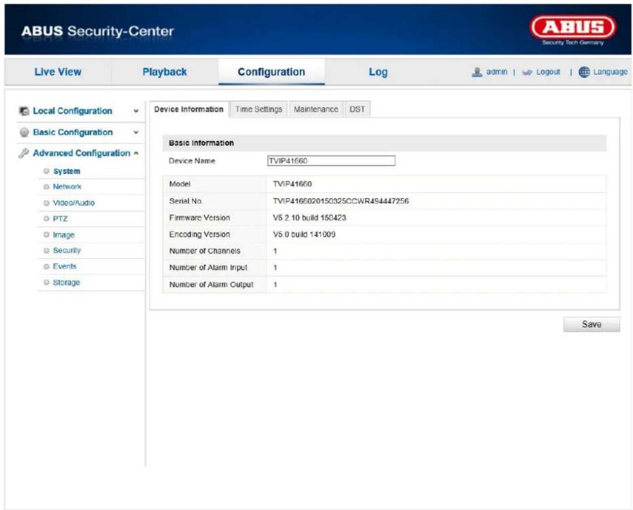
12.3.1.1. Device Information

Basic Information
Device Name:
You can specify a device name for the camera here. Click on "Save" to apply the change.
Model:
Model number display
Serial No.:
Serial No. display
Firmware Version:
Firmware version display
Encoding Version:
Encoding version display
Number of Channels:
Display of the number of channels
Number of Alarm Input:
Displays the alarm inputs
Number of Alarm Output:
Displays the alarm outputs
12.3.1.2. Time Settings

Time Zone
Time zone selection (GMT).
Time Sync.
NTP
Using the Network Time Protocol (NTP), it is possible to synchronise the time of the camera with a time server.
Enable NTP to use this function.
Server Address
IP server address of the NTP server.
NTP Port
Network port number of the NTP service (default: port 123)
Interval
The interval for synchronising the time is entered here in minutes.
Click on "Test" to start a test run.
Manual Time Sync.
Device Time
Computer device time display.
Set Time
Display of the current time using the time zone setting.
Click on ""Sync. with computer time" to adopt the device time on the computer.

Apply the settings by clicking "Save".
Reboot
Click "Reboot" to reboot the device.
Default
Restore
Click ""Restore" to restore all the parameters to default settings, except the IP parameters.
Default
Select this item to restore all parameters to default settings.
Import Config. File
Config File
Select a file path to import a configuration file here.
Status
Display of the import status
Export Config. File
Click "Export" to export a configuration file.
Remote Upgrade
Firmware
Select the path to upgrade the camera with new firmware.
Status
Display of the upgrade status.

Apply the settings by clicking "Save".
12.3.1.4. DST

DST
Enable DST
Select "Enable DST" to adjust the system time automatically to daylight saving time.
Start Time
Specify the time for switching to daylight saving time.
End Time
Specify the time for switching to standard time.
DST Bias
Set the time difference in minutes here.

Apply the settings by clicking "Save".
12.3.2. Network
| Menu item | Description | Available in mode |
| TCP/IP | Settings for the TCP/IP data | Basic Configuration, Advanced Configuration |
| Port | Settings for the used ports | Basic Configuration, Advanced Configuration |
| DDNS | Settings for the DDNS data | Advanced Configuration |
| Wi-Fi | Settings for the W-LAN access data | Advanced Configuration |
| UPnPTM | Settings for the UPnP data Advanced Configuration |
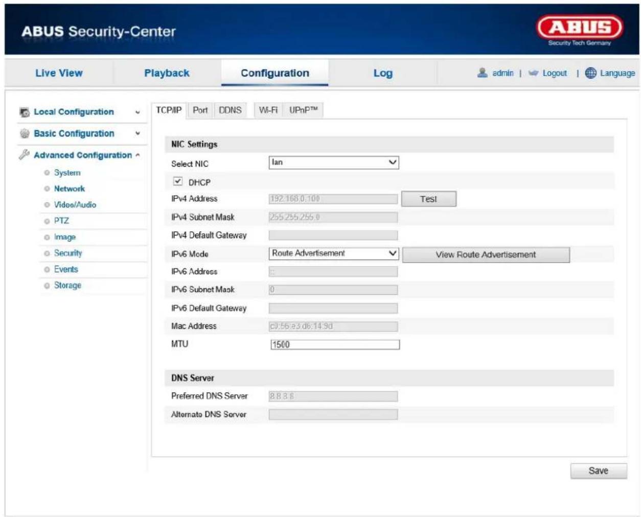
12.3.2.1. TCP/IP

To be able to operate the camera via a network, the TCP/IP settings must be configured correctly.
Select NIC:
Choose the network interface to configure. The camera can either be connected to the network via LAN or WLAN.
DHCP
If a DHCP server is available, click DHCP to apply an IP address and other network settings automatically. The data is transferred automatically from the server and cannot be changed manually.
If no DHCP server is available, please enter the following data manually.
IPv4 Address
Setting of the IP address for the camera
IPv4 Subnet Mask
Manual setting of the subnet mask for the camera
IPv4 Default Gateway
Setting of the default router for the camera
IPv6 Mode
Manual: Manual configuration of IPv6 data.
DHCP: The IPv6 connection data is provided by the DHCP server.
Route Advertisement: The IPv6 connection data is provided by the DHCP server (router) in connection with the ISP (Internet Service Provider).
IPv6 Address
Display of the IPv6 address. The address can be configured in the IPv6 "manual" mode.
IPv6 Subnet Mask
Display of the IPv6 subnet mask.
IPv6 Default Gateway
Display of the IPv6 default gateway (default router).
MAC Address
The IPv4 hardware address of the camera is displayed here. This cannot be changed.
MTU
Setting of the transmission unit. Select a value between 500 and 9676. 1500 is set by default.
DNS Server
Preferred DNS Server
DNS server settings are required for some applications (for example, sending emails). Enter the address of the preferred DNS server here.
Alternative DNS Server
If the preferred DNS server cannot be reached, this alternative DNS server is used. Please store the address of the alternative DNS server here.

Apply the settings by clicking "Save".
12.3.2.2. Port

If you wish to enable external access to the camera, the following ports must be configured.
HTTP Port
The default port for HTTP transmission is 80. This port can alternatively be assigned a value in the range of 1024\~65535. If several cameras are located on the same subnetwork, each camera should have its own unique HTTP port.
RTSP Port
The default port for RTSP transmission is 554. This port can alternatively be assigned a value in the range of 1024\~65535. If several cameras are located on the same subnetwork, each camera should have its own unique RTSP port.
HTTPS Port
The standard port for HTTPS transmission is 443.
SDK Port (control port)
The standard port for SDK transmission is 8000. Communication port for internal data. As an alternative, this port can be assigned a value in the range 1025 \~ 65535. If several IP cameras are located in the same subnetwork, each camera should have its own unique server port.

Apply the settings by clicking "Save".
12.3.2.3. DDNS
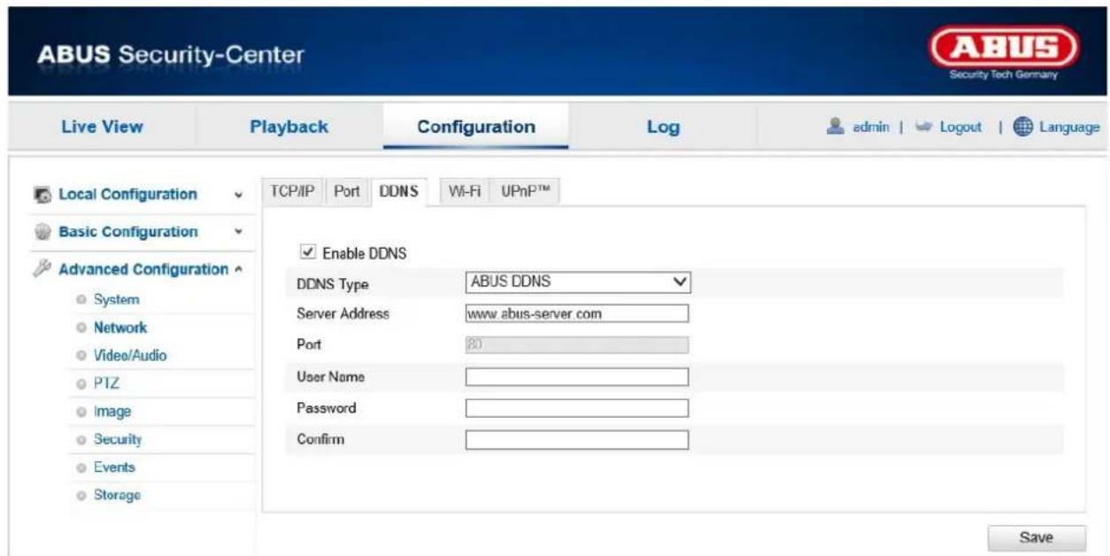
DDNS
DynDNS or DDNS (dynamic domain name system entry) is a system that can update domain name entries in real time. The network camera is equipped with an integrated DynDNS client that updates the IP address independently via a DynDNS provider. If the network camera is located behind a router, we recommend using the router's DynDNS function.
The following diagram offers an overview of accessing/updating the IP address using a DynDNS service.

flowchart
graph TD
    A["① 192.168.0.3"] --> B["Router"]
    B --> C["② 195.184.21.78"]
    B --> D["③ DynDNS access data"]
    D --> E["Internet"]
    E --> F["DynDNS.org\nName Server"]
    F --> G["④ 195.184.21.78 → name.dyndns.org"]
Enable DDNS
Enable or disable the DDNS function.
DDNS Type
Select the DDNS type. You can choose between "DynDNS" and "ABUS DDNS".
Server Address
Select a DDNS service provider. You must have registered access to this DDNS service provider (e.g. www.dyndns.org).
If you select "ABUS DDNS" as the DDNS type, the server address is stored automatically.
Domain
Enter the registered domain name (host service) here (e.g. myIPcamera.dyndns.org).
Port
Store the port for port forwarding here.
User name
User ID of your DDNS account
Password
Password of your DDNS account
Confirm
You must confirm your password here.
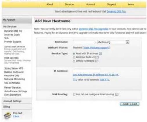
Setting up a DDNS account
Set up a new account under DynDNS.org:

Store your account information:
DynDNS.com
![Add New Hostname Note: You currently don't have any active Dynamic DNS Pro upgrade in your account. You cannot use or feature. Paying for an Dynamic DNS Pro upgrade will make the form fully functional and will add several Hostname: .svdms.org Wildcard Status: Insured (Start Wildband support) Service Type: Host with IP address [1] Webpage Redirect [2] Office Hostname [3] If Address: the auto-detected IP address $2.75, 16, 44. [1], value is 60 seconds. Add TTS. Mail Resetting: Yes, let me configure Email routing. [4] Add to Cart My Account My Services Dynamic DNS Pro Internet Guide SLA Premier Support Zone Level Services Storage installation and transfer, DNS Holdings, Hosting Service Host Services Dynamic DNS Pro, Hosting Service SPR Forwarding Spring Server IPS Makeup Outbound Exclusive DNS Network Monitoring SSL Certificates Renew Services Auto Renew Settings Sync Operations Account Settings Billing My Cart Libos](/content/2026/06/1272054/images/6dac178413848a51885e0a71c7431062f6f05e67e60ef260016f3e366f8d85ef.jpg)
Note down your user data and enter this into the configuration of the network camera.
Accessing the network camera via DDNS
If the network camera is located behind a router, access via DynDNS must be configured in the router. On the ABUS Security-Center homepage www.abus-sc.com, you can find a description of the DynDNS router configuration for common router models.
The following diagram offers an overview of accessing a network camera behind a router via DynDNS.org.

flowchart
graph TD
    A["User"] -->|⑤ 192.168.0.1| B["Server"]
    B -->|④ 195.184.21.78:1026| C["Internet"]
    C -->|③ 195.184.21.78:1026| D["DynDNS.org Name Server"]
    D -->|② name.dyndns.org:1026 → 195.184.21.78:1026| E["Laptop"]
    C -->|① http://name.dyndns.org:1026| F["Computer"]
    B -->|LAN| G["Computer"]
    style A fill:#f9f,stroke:#333
    style B fill:#ccf,stroke:#333
    style C fill:#cfc,stroke:#333
    style D fill:#fcc,stroke:#333
    style E fill:#cff,stroke:#333
    style F fill:#ffc,stroke:#333

Port forwarding of all relevant ports (at least RTSP + HTTP) must be set up in the router in order to use DynDNS access via the router.

Apply the settings by clicking "Save". If the network configuration is changed, the camera must be rebooted (System/Maintenance/Reboot).
ABUS DDNS
- To be able to use the ABUS DDNS function, you first need to set up an account at www.abus-server.com. Please read the FAQs on this topic on the website.
- Select the "Enable DDNS" checkbox and select "ABUS DDNS" as the DDNS type.

Apply the settings by clicking "Save".
12.3.2.5. Wi-Fi

The following settings must be made to create a Wi-Fi connection between the camera and the router.
Wireless List
Click "Search" to display available networks in the immediate vicinity.

Wi-Fi
SSID
Enter the name of the network here.
Network Mode
You can choose between Manage and Ad-Hoc here.
Manage
Select this item for a connection to a network.
Ad-Hoc
Select this item for a direct connection to a PC or laptop.
Security Mode
Here you can select the encryption type for your network.
Encryption Type:
Here you can select the encryption type for the network.
Key 1
Enter the network key (password) for access to the network here.
WPS
The WPS function allows simple set-up of a wireless connection of the camera to a Wi-Fi network.
Enable WPS
Enable this function to use a WPS connection.

Please check whether your router supports the WPS function.
PIN Code
The PIN code is required for creating the connection. By default, this is set to 12345678. Click on "Generate" to generate a new code.
PBC Connection
If your router has a WPS button, enable this function.
- First, press the WPS button on the router.
- Then click on "Connect" within two minutes.
- The WLAN connection between the camera and router is established after a short time.
PIN code of the router
Here, you can establish a WPS connection manually by entering the SSID and the router PIN code.
SSID: Enter the SSID for the desired network.
Router PIN Code: Enter the router PIN code. Refer to the user guide from your router's manufacturer to read out the WPS PIN code.

Apply the settings by clicking "Save".
12.3.2.6. UPnP TM

The UPnP (Universal Plug and Play) function makes it easy to control network devices in an IP network. This allows the network camera to be seen in the Windows network environment (e.g. as a network device).
Enable UPnP TM
For enabling or disabling the UPnP function.
Friendly Name
Display of the MAC address of the camera
Port Mapping
Enable Port Mapping
This enables Universal Plug and Play port forwarding for network services. If your router supports UPnP, then port forwarding for video streams is enabled automatically on the router for the network camera using this option.
Port Mapping Mode
Select here whether you wish to conduct port mapping automatically or manually.
Protocol Name:
HTTP
The default port for HTTP transmission is 80. As an alternative, this port can be assigned a value in the range 1025 \~ 65535. If several IP cameras are located on the same subnetwork, each camera should have its own unique HTTP port
RTSP
The default port for RTSP transmission is 554. As an alternative, this port can be assigned a value in the range 1025 \~ 65535. If several IP cameras are located on the same subnetwork, each camera should have its own unique RTSP port.
Server Port (control port)
The standard port for SDK transmission is 8000. Communication port for internal data. As an alternative, this port can be assigned a value in the range 1025 \~ 65535. If several IP cameras are located in the same subnetwork, each camera should have its own unique server port.
External Port
You can only change ports manually here if the "Port Mapping Mode" was set to manual.
External IP Address
Display the external IP address for mobile access.
Status
Displays whether the external port entered is valid or not valid.

Apply the settings by clicking "Save".
12.3.3. Video/Audio
| Menu item | Description | Available in mode |
| Video | Settings for video output | Basic Configuration, Advanced Configuration |
| Audio | Settings for audio output Basic Configuration, | Advanced Configuration |
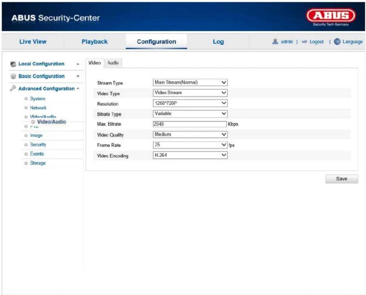
12.3.3.1. Video

Stream Type
Select the stream type for the camera. Select "Main Stream (Normal)" for recording and live view with good bandwidth. Select "Sub Stream" for live view with restricted bandwidth.
Video Type
Set the video type for the selected stream here. You can select between
"Video & Audio" and "Video Stream", there is no audio transmission for the latter.
Resolution
Set the resolution of the video data here. Depending on the camera model you can choose between 1280*720p and 1280*960;
Bitrate Type
Specifies the bitrate of the video stream. The video quality can be higher or lower depending on the intensity of movement. You can select between a constant and variable bitrate.
Max. Bitrate
The bitrate of the video stream is set to a certain value. Set a max. bitrate of between 32 and 16384 Kbps. A higher value means better video quality; however, this requires more bandwidth.
Video Quality
This menu item is only available if you have selected a variable bitrate. Set the video quality for video data here. The video quality can differ depending on the intensity of movement. You can select from six different video qualities: "Lowest", "Lower", "Low", "Medium", "Higher" or "Highest".
Frame Rate
Specifies the frame rate in frames per second.
Video Encoding
Select a default for video encoding. You can choose between H.264 and MJPEG.

Apply the settings by clicking "Save".
12.3.3.2. Audio
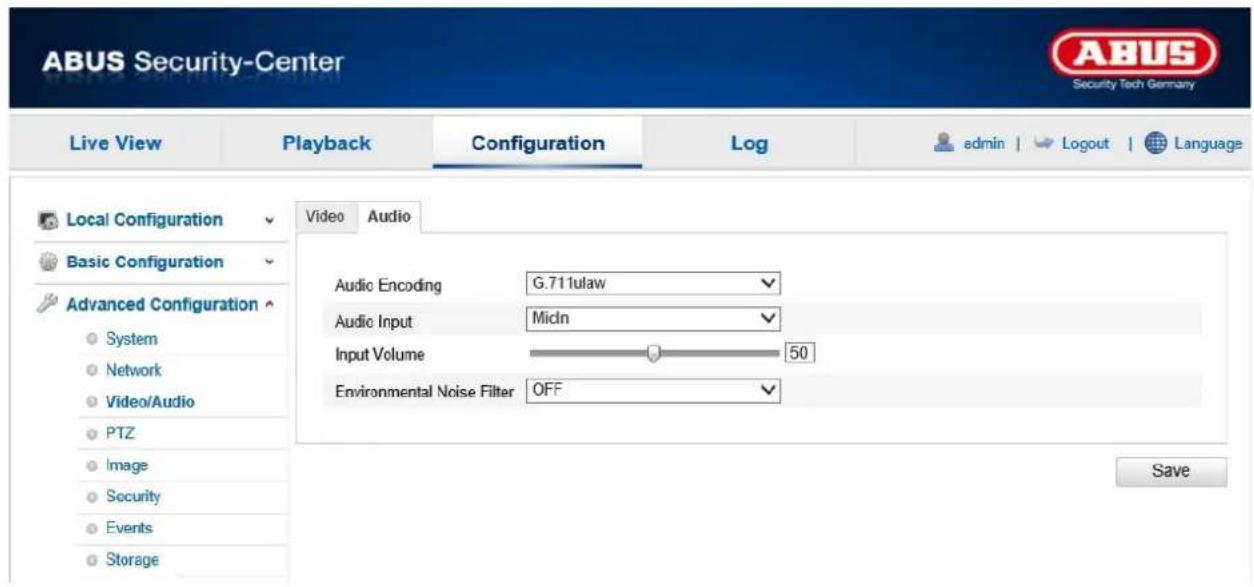
Audio Encoding
Select the encoding for audio transmission here.
You can choose between "G.711ulaw", "G.711alaw" and "G.726".
Audio Input
Set the audio input to MicIn to use the microphone or to LineIn to use the audio input.
Input volume
Setting the volume output
Environmental noise filter
Enable this filter to filter out environmental noises.

Apply the settings by clicking "Save".
12.3.4. PTZ

| Menu item | Description | Available in mode |
| Basic | Setting for PTZ basics Advanced | Configuration |
| Initial Position | Settings for initial position Advanced | Configuration |
| Scheduled Tasks | Setting for scheduled tasks Advanced | Configuration |
| Clear configuration | Settings to clear PTZ configuration Advanced | Configuration |
12.3.4.1. Basic
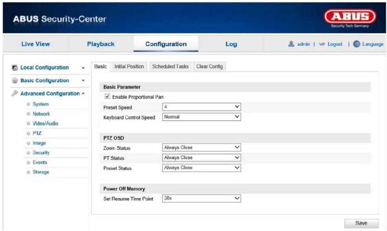
Basic Parameters
Enable Proportional Pan
Enable this function to adjust the pan / tilt speed to the respective zoom level. With a high zoom level, the pan / tilt speed is lower to that the picture does not move too quickly in the live view.
Preset Speed
You can select a predefined preset speed of between 1 and 8 here.
Keyboard Control Speed
You can adjust the response speed using the control desk. You can choose between "Low", "Normal" and "High".
PTZ OSD
Zoom status
Set the display duration for the zoom status here. You can select from between 2 seconds, 5 seconds, 10 seconds, "Always Close" and "Always Open".
PT Status
Set the display duration for the azimuth angle during swivelling and tilting here.
You can select from between 2 seconds, 5 seconds, 10 seconds, "Always Close" and "Always Open".
Preset Status
Set the display duration for the preset names when calling up a preset position here.
You can select from between 2 seconds, 5 seconds, 10 seconds, "Always Close" and "Always Open".
Power off memory
Set Resume Time Point
After a reboot, the camera can resume with the last PTZ status or the last executed action. Here, you can specify the time after which the resumption of the last action is started. You can select from between 30 seconds, 60 seconds, 300 seconds or 600 seconds.

Apply the settings by clicking "Save".
12.3.4.2. Initial Position

The initial position is the starting point of the PTZ coordinates. This can be both adjusted and changed manually.
To define an initial position manually, proceed as follows. Use the PTZ control buttons to switch to the desired position. You have the option of specifying a previously defined preset position as the initial position.
Click on "Set" to save the position. You can call a predefined initial position using "Go to". To remove an initial position, click on "Clear".

Apply the settings by clicking "Save".
12.3.4.3. Scheduled Tasks

Here, you can define a schedule to determine which actions are performed on certain days of the week and at what times.
First activate the "Enable Scheduled Task" check box.
Now determine a park time after which the Speed Dome camera is to start a scheduled task.
Configure the schedule as follows: Click "Edit Tasks".
The following window appears.
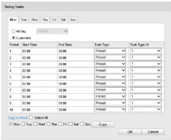
Now select a week day for the scheduled task. Select "All Day" if the task is to be executed all day long. To save certain time periods, select "Customize". Enter the start and end times, select a task type and confirm your entry with ENTER.
To apply the configured task for all week days, click the "Select All" check box. To copy the task to certain other week days, select the week day and click on "Copy".
To apply the changes, click "OK" and to discard them click "Cancel".

Apply the settings by clicking "Save".
12.3.4.4. Clear configuration

With this menu item, you can clear PTZ configurations.
Activate the check box of the elements you wish to clear. Select "Select All" to clear all of the items.

Apply the settings by clicking "Save".
12.3.5. Image

| Menu item | Description | Available in mode |
| Display Settings | Displaying parameter settings | Basic Configuration, Advanced Configuration |
| OSD Settings | Setting the date and time format Advanced Configuration | |
| Text Overlay | Adding text fields | Advanced Configuration |
| Privacy Masking | Adding privacy masking Advanced Configuration |
12.3.5.1. Display Settings
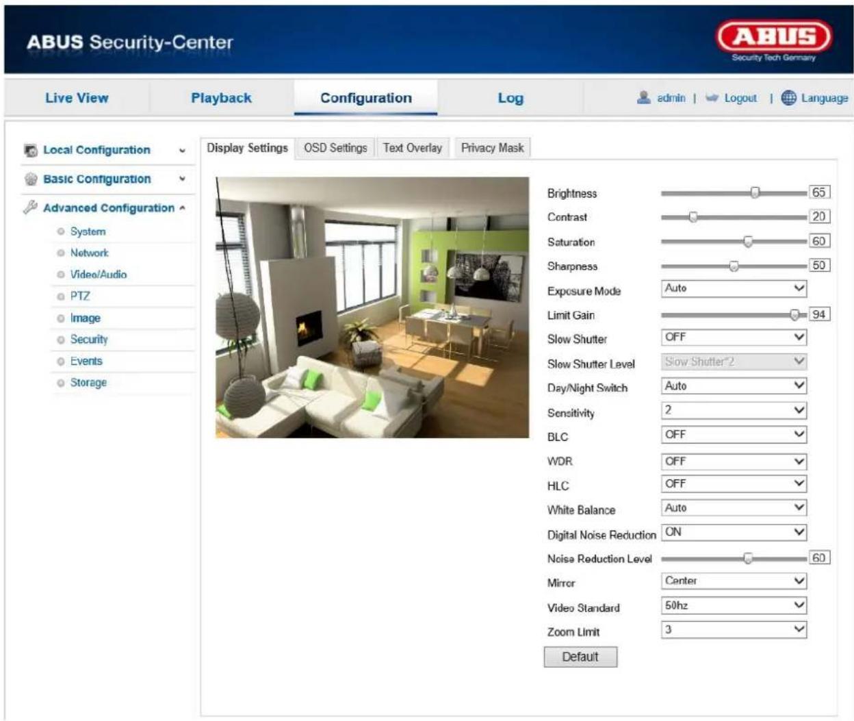
You can use this menu item to set the picture quality of the camera, including brightness, sharpness, contrast, etc.
Please note:
The display setting parameters can vary depending on the model.
Switch Day and Night
Here, you have the option between automatic day & night switch and the scheduled switch. A start and end time must be saved for the day mode here.
The following settings can be made individually for the day or night mode.
Brightness
Image brightness settings. A value between 0 and 100 can be set.
Contrast
Image contrast settings. A value between 0 and 100 can be set.
Saturation
Image saturation settings. A value between 0 and 100 can be set.
Hue
Setting for the image hue. A value between 0 and 100 can be set.
Sharpness
Image sharpness settings. A higher sharpness value can increase image noise.
A value between 0 and 100 can be set.
Exposure Mode
Set the exposure mode to Auto for adjustment to different exposures. With a manual exposure mode, you need to set the exposure time yourself.
Exposure Time
Setting the maximum exposure time. This setting is dependent on iris mode.
Day/Night Switch
Day/Night Switch Provides options for Auto, Day and Night time schedule and triggered by alarm input.
Auto
Depending on the light conditions, the camera switches between day and night mode automatically. The sensitivity can be set between "0 and 7", where 7 is the highest sensitivity level.
Day
In this mode, the camera only outputs colour pictures.

Please note:
Only use this mode if the light conditions remain constant.
Night
In this mode, the camera only outputs black/white pictures.

Please note:
Only use this mode if the light conditions are poor.
Schedule
In this mode, you can set the start and end time for day operation. Outside of the set interval, the camera switches to black/white mode.
Triggered by Alarm Input
The camera is triggered by the alarm input and changes to colour or black/white mode if there is a change in status.
Status
Choose night, so that the camera switches to black/white mode if the alarm input is triggered. Choose day, if the should switch to colour mode if the alarm input is triggered.
Sensitivity
Setting for the switching threshold for automatic day/night switching (0–7).
A lower value means that there is a lower lighting level for switching to night mode.
Filtering Time
Setting a delay time between recognising that a switching is required and carrying out the process.
Smart IR
If this function is activated, the IR light intensity is automatically reduced for objects that are too close. This attempts to prevent object cross fading.
BLC Area (Backlight Compensation)
Objects in front of a bright background can be shown more clearly with the aid of the backlight compensation. The exposure of the objects is corrected, however the background is not shown in focus.
WDR
With the aid of the WDR function, the camera can return clear pictures even in disadvantageous backlight conditions. If there are both very bright and very dark areas in the picture area, the brightness level of the overall picture is balanced to provide a clear, detailed image.
Click on the checkbox to enable or disable the WDR function.
Set the Wide Dynamic Level higher to enhance the WDR function.
White balance
Here you select the lighting conditions in which the camera is installed.
You can choose between the options "AWB1", "Locked WB", "Incandescent Lamp", "Warm Light Lamp", "Natural Light", "Fluorescent Lamp".
AWB1
In AWB1 mode, the camera retains the colour balance automatically depending on the current colour temperature.
Locked WB
The white balance is performed once and saved.
Other
Use the additional white balance options to adjust the function to the light level (incandescent lamp, warm light lamp, natural light, fluorescent lamp).
Noise Reduction Level
Set the level for noise reduction here.
Mirror
If the mirror function is active, the image is mirrored horizontally.
Rotate
If the rotate function is active, the image is mirrored vertically.
Video Standard
Regulation of the exposure frequency
50 Hz: Fixed setting to 50 Hz network frequency
60 Hz; Fixed setting to 60 Hz network frequency
12.3.5.2. OSD Settings

You can use this menu item to select which date and time format are displayed in the live picture.
Display Name
Activate this checkbox if you wish to display the camera name.
Display Date
Activate this checkbox if you wish to display the date in the camera image.
Display Week
Activate this checkbox if you wish to display the day of the week.
Camera Name
Enter the camera name that is to be displayed in the image here.
Time Format
Choose here whether you would like to display the time in 24-hour or 12-hour format.
Date Format
Select the format for the date display here.
(D = day; M = month, Y = year)
Display Mode
Here you can select the display mode for the elements displayed.
You have the following options: "Transparent & Flashing", "Transparent & Not Flashing", "Not Transparent & Flashing", "Not Transparent & Not Flashing".
OSD Size
The on-screen display size can be set here. Options: 16x16, 32x32, 48x48, 64x64, auto.
In the auto option, the size is adjusted according to the resolution set. The OSD size setting can only be applied to the first video stream (main stream).

Apply the settings by clicking "Save".
12.3.5.3. Text Overlay
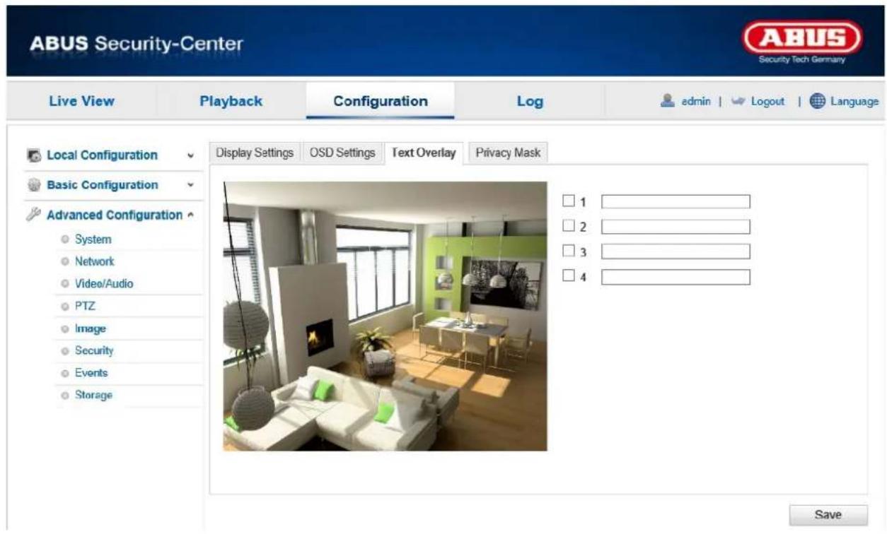
You have the option to display up to four texts in the camera image. The maximum length is 45 characters. To display the text, please activate the checkbox.
You can move the text window with the mouse button.

Apply the settings by clicking "Save".
12.3.5.4. Privacy Mask

You can use privacy masks to hide certain areas in the live view to prevent these areas from being recorded and viewed in the live view. A maximum of 8 rectangular privacy masks can be set up in the video image.
To set up a privacy mask, proceed as follows. Select the checkbox
"Enable Privacy Mask". Use the PTZ control or the predefined presets to choose the desired position. To add a privacy mask, click "Draw Area". You can now select an area on the camera image using your mouse. Then press the "Add" button. You can then select and add 7 additional areas. By clicking on "Clear All", you can delete all marked areas. To remove a privacy mask, select it in the table below and click on the 'Delete' button.
After you have added a privacy mask, you can allocate a name to it in the table. You can also quickly deactivate privacy masks in the 'Enable' column.
In the column 'Enable zoom ratio', you can define the zoom level at which the privacy mask appears. For example, with a set value of 3", the privacy mask will appear when the zoom level has reached 3".

Apply the settings by clicking "Save".
12.3.6. Security

| Menu item | Description | Available in mode |
| User | User administration | Basic Configuration, Advanced Configuration |
| IP Address Filter | Filtering IP addresses to gain access for controlling the camera | Advanced Configuration |
12.3.6.1. User

With this menu item, you can add, edit or delete users.
To add or modify a user, click "Add" or "Modify".
A new window with the data and authorisations appears.
User name
Here you assign the user name that needs to be entered for access to the camera.
Level
Select an individual user type for the user ID.
You can choose between two predefined levels: "Operator" or "User".
As an operator, the following remote functions are available to you: Live view, PTZ control, manual recording, playback, two-way audio, search/query operating status.
As a user, the following remote functions are available to you: playback, browse/query operating status.
To add further functions, select the corresponding checkbox.
Password
Here you assign the password that the corresponding user must enter to access the camera.
Confirm
Confirm the password by entering it again.

Apply the settings by clicking "Save".
12.3.6.2. IP Address Filter

Enable IP Address Filter
Ticking the selection box enables the filter function.
IP Address Filter Type
Allowed: The IP addresses detailed further below can be used to access the camera.
Forbidden: The IP addresses detailed further below are blocked. An IP is entered in the format xxx.xxx.xxx.xxx.
12.3.7. Basic Event

| Menu item | Description | Available in mode |
| Motion detection | Settings for motion detection Advanced Configuration | |
| Alarm Input | Setting for the alarm input Advanced Configuration | |
| Alarm Output | Setting for the alarm output Advanced Configuration | |
| Email send setting Advanced Configuration | ||
| Snapshot | Setting for the snapshot action Advanced Configuration |
12.3.7.1. Motion detection

Area Settings
Activate motion detection by clicking the "Enable Motion Detection" checkbox.
To select an area, click on the "Draw Area" button. The entire area is selected by default. To discard this selection, click on "Clear All".
Drag the mouse pointer over the desired area. Set the sensitivity using the regulation control bar. To apply the setting for the area, click on "Stop Drawing".
Right: high sensitivity
Left: low sensitivity.
Arming Schedule
To save a schedule for motion-controlled recording, click on "Edit".
A new window appears. Specify here on which days of the week and at which times motion-controlled recording should take place.

Now select a day of the week for motion-controlled recording. To store particular time periods, enter a start and end time. To set up all-day motion detection, select 00:00 as the start time and 24:00 as the end time.
To apply motion detection for all days of the week, click the "Select All" checkbox. To copy motion detection to other days of the week, select the day of the week and click on "Copy".
To apply the changes, click "OK" and to discard them click "Cancel".
Apply the settings made by clicking "Save".
Link Method
Send email:
You receive an email as notification; check the checkbox to activate this.
Notify Surveillance Centre
If your camera has been set up for this, you can send a notification to the CMS.
Enable recording:
Enables recording to the internal microSD card.
Other Linkage
You can set the alarm output to switch when an alarm is detected.
Click on "Select All" to switch the alarm output.

Apply the settings by clicking "Save".
12.3.7.3. Alarm Input

You can configure the camera's alarm input under this menu item.
Alarm Input No.
Select the alarm input here to configure it.
Alarm Name
You can specify a name for the alarm input here. Please do not use the alarm input no. or any special characters.
Alarm Type
Select the alarm type here. You can choose between "NO" (normally open) or "NC" (normally closed).
Arming Schedule
To save a schedule for an alarm input, click on "Edit".
A new window appears. Specify here on which days of the week and at which times the alarm input should be enabled.

Now select a day of the week for the alarm input. To store particular time periods, enter a start and end time. To activate the alarm input all day, select 00:00 as the start time and 24:00 as the end time. To apply the settings for all days of the week, click the "Select All" checkbox. To copy the settings to other days of the week, select the day of the week and click on "Copy". To apply the changes, click "OK" and to discard them click "Cancel".
Linkage Method
Here you can set the action to be performed in case of an alarm.
Linkage Method
Send email:
You receive an email as notification; check the checkbox to activate this.
Notify Surveillance Centre
If your camera has been set up for this, you can send a notification to the CMS.
Enable recording:
Enables recording to the internal microSD card.
Other Linkage
You can set the alarm output to switch when an alarm is detected. Click on "Select All" to switch the alarm output.
PTZ Linking: Choose a preset position to which the camera should pan if the alarm is triggered.
12.3.7.4. Alarm Output
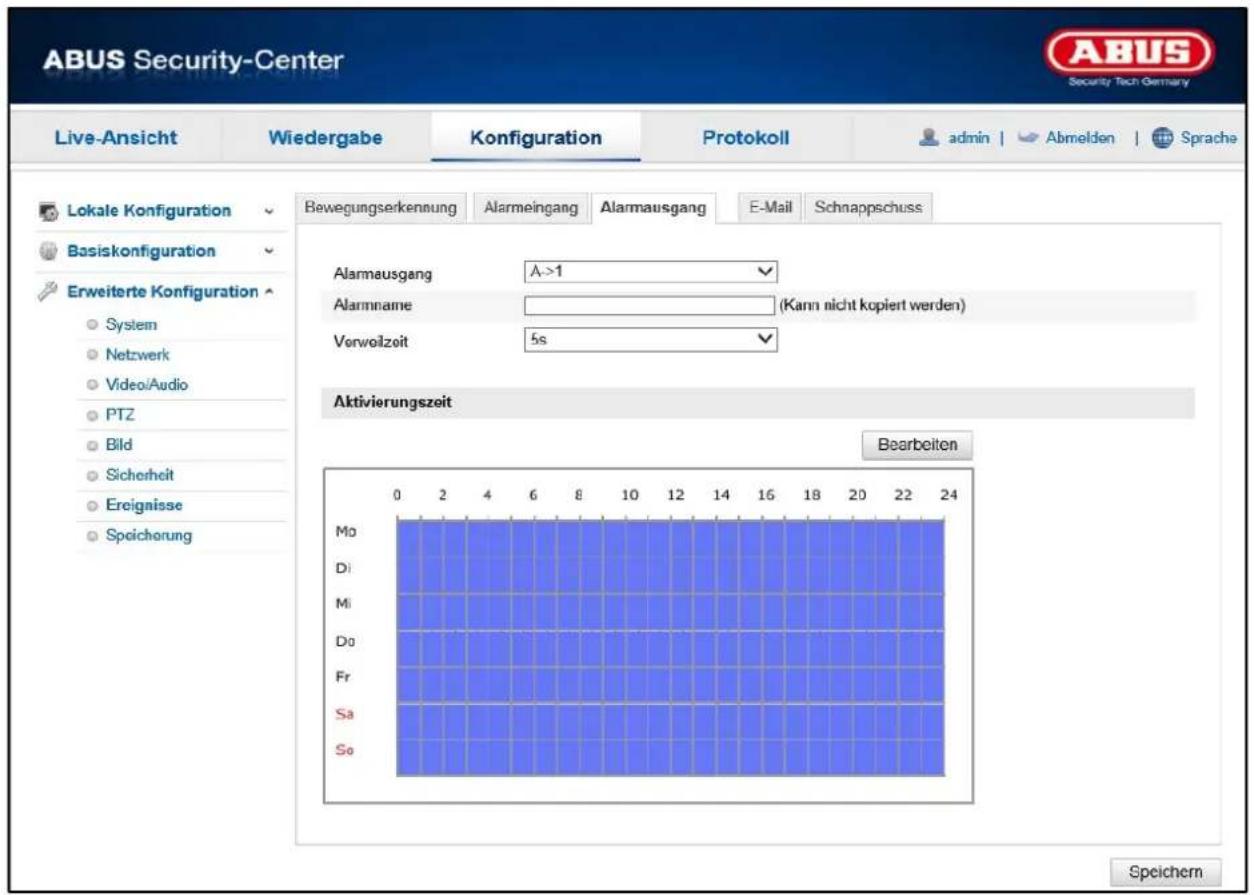
You can configure the alarm output here.
Alarm Output No.
Select the alarm output here to configure it.
Alarm Name
You can specify a name for the alarm output here. Please do not use the alarm output no. or any special characters.
Dwell Time
Select the duration for the switching of the alarm output.
Arming Schedule
To save a schedule for the alarm output, click on "Edit".
A new window appears. Specify here on which days of the week and at which times the alarm output should be enabled.

Now select a day of the week for the alarm output. To store particular time periods, enter a start and end time. To activate the alarm input all day, select 00:00 as the start time and 24:00 as the end time. To apply the settings for all days of the week, click the "Select All" checkbox. To copy the settings to other days of the week, select the day of the week and click on "Copy".
To apply the changes, click "OK" and to discard them click "Cancel".
12.3.7.5. Email

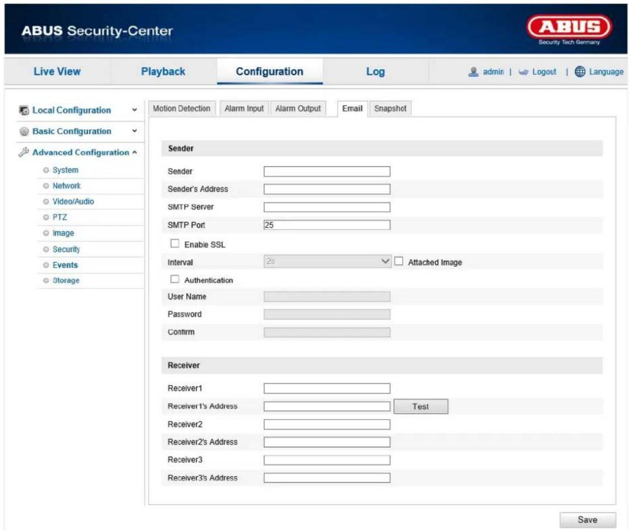
You can apply the settings for sending emails here.
Sender
Sender
Enter a name here to be displayed as the sender.
Sender's Address
Enter the email address of the sender here.
SMTP Server
Enter the IP address or host name of the SMTP server here. (For example: smtp.googleapis.com)
SMTP Port
Enter the SMTP port here. This is configured as 25 by default.
Enable SSL
Select the SSL function if the SMTP server requires this.
Interval
Set the interval between sending emails with image attachments here.
Attached Image
Enable this function if images are to be attached to the email in the event of an alarm.
Authentication
If the email server in use requires authentication, enable this function to be able to log onto the server with authentication.
User names and passwords can only be entered once this function has been enabled.
User name
Enter the user name of the email account here. This is the part before the @ symbol.
Password
Enter the password of the email account here.
Confirm
Confirm the password by entering it again.
Receiver
Receiver1/Receiver2/Receiver3
Enter the name of the receiver here.
Receiver1's Address/Receiver2's Address/Receiver3's Address
Enter the email address of the person to be informed here.
Click on "Test" to send a test email.

Apply the settings by clicking "Save".
12.3.7.6. Snapshot
Here, you can set the configuration for time and event-triggered snapshots in order to be able to save them to the microSD card.
Timing
Enable Timing Snapshot
Enable this function to save pictures at certain intervals.
Format
The format for the pictures is preconfigured as JPEG.
Resolution
Set the resolution of the picture here.
Quality
Select the quality for the saved pictures here.
Interval
Set the interval to occur between the saving of two pictures here.
Event-Triggered
Enable Event-Triggered Snapshot
Enable this function to save event-triggered pictures.
Format
The format for the pictures is preconfigured as JPEG.
Resolution
Set the resolution of the picture here.
Quality
Select the quality for the saved pictures here.
Interval
Set the interval to occur between the saving of two pictures here.
Capture Number
Set the number of images that should be saved for an event here.
12.3.8. Storage

| Menu item | Description | Available in mode |
| Record Schedule | Set up a scheduled recording | Advanced Configuration |
| Storage Management | Management of the SD card Advanced Configuration |
12.3.8.2. Recording plan

Here, you can set the configuration for time and event-triggered recordings in order to be able to save them to an SD card.
Pre-record
Set the duration for recording of the image data before a basic event here.
Post-record
Set the duration for recording of the image data after a basic event here.
Enable Record Schedule
Enable the schedule to store the desired schedule.
To store the schedule, click "Edit". A new window opens.

Now select a day of the week for the recording to take place. To store particular time periods, enter a start and end time. To activate the alarm input all day, select 00:00 as the start time and 24:00 as the end time.
To apply the settings for all days of the week, click the "Select All" checkbox. To copy the settings to other days of the week, select the day of the week and click on "Copy".
Under Record Type, select the recording mode for the desired schedule. You can
choose between the following record types:
Normal: permanent recording.
Motion detection: motion-triggered recording.
Motion detection | Alarm: recording triggered by motion or by alarm input. Camera begins recording either following motion detection or an alarm input.
Motion detection & Alarm: recording triggered by motion and by alarm input. Camera only starts recording if motion and alarm input are triggered simultaneously.

Please note that the motion detection mask and the alarm input must be configured.
To apply the changes, click "OK" and to discard them click "Cancel".

Apply the settings by clicking "Save".
12.3.8.3. Storage Management

Here you can format the inserted microSD card and display its properties.
Percentage of Picture
Enter the percentage that should be taken up by snapshot images here.
Percentage of Record
Enter the percentage that should be taken up by recordings here.
Please format the SD card before using it for the first time!
13. Log
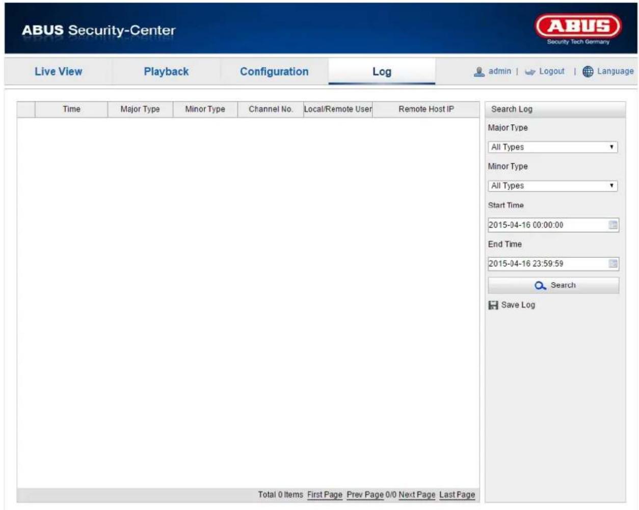
Camera parameters, such as alarm, exceptions, operation and information can be saved in the log files. The files can be exported if necessary.
- Click on Log in the menu bar to call up the search dialogue.
- Specify the search criteria, including Major Type, Minor Type, Start Time and End Time.
- Click on Search to search for log files. The corresponding log files are displayed in the log dialogue.
- Click on Save Log to export the log files and save them on your computer.
14. Maintenance and cleaning
14.1. Maintenance
Regularly check the technical safety of the product, e.g. check the housing for damage.
If it appears to no longer be possible to operate the product safely, stop using it and secure it to prevent unintentional use.
It is likely that safe operation is no longer possible in the event that:
- the device shows signs of visible damage
- the device no longer works correctly.

Please note:
You do not need to perform any maintenance on the product. There are no components to service and nothing inside the product to check. Never open it.
14.2. Cleaning
Clean the product with a clean, dry cloth. The cloth can be dampened with lukewarm water to remove stubborn dirt.

Do not allow any liquids to enter the device.
Do not use any chemical cleaning products as they could damage the surface of the housing and screen (discolouration).
15. Disposal

Important: EU Directive 2002/96/EC regulates the proper return, treatment and recycling of used electronic devices. This symbol means that in the interest of environmental protection, the device must be disposed of separately from household or industrial waste at the end of its service life in accordance with applicable local legal guidelines. Used devices can be disposed of at official recycling centres in your country. Obey local regulations when disposing of material. Further details on returns (also for non-EU countries) can be obtained from your local authority. Separate collection and recycling conserves natural resources and ensures that all the provisions for protecting health and the environment are observed when recycling the product.
- Technical data
| Model number | TVIP41660 |
| Dimensions (D x H) | 120 x 84 mm |
| Alarm input (NO/NC) | 1. |
| Danger detection | Email, recording on SD card |
| Connections | 1 x RJ45, 1 x audio input, 1 x audio output, 1 x DC1 x alarm input, 1 x alarm output |
| Number of parallel streams | 2 |
| Audio output | 2-wireAudio compression: G.711/G.726/MP2L2/G.722 |
| Resolution modes | Main Stream: 1280 x 960, 704 x 576, 640 x 480Sub Stream: 704 x 576, 640 x 480, 352 x 288, 320 x 240 |
| Motion detection | Yes |
| Image sensor | 1/3 inch progressive scan CMOS |
| Pixels (effective) | 1280 x 960 pixels |
| Image overlay | Date, camera name, private zones |
| Frame rate | 25 fps |
| Focal length | 4.0 mm @ F2.0 |
| Camera type | Day/night |
| Dynamic range (WDR) | Digital WDR |
| Electronic shutter regulation | 1/3 - 1/100000 Sec. |
| Backlight compensation | BLC, DWDR |
| Simultaneous network access | Yes |
| Horizontal angle of view | 33-80° |
| Camera type | Day/night pan/tilt/zoom camera |
| Max. resolution @ frame rate | 1280 x 960 @ 25 fps |
| Max. operating temperature | 50°C |
| Max. humidity | 90% |
| Microphone | Yes |
| Min. operating temperature | -10°C |
| Minimum illumination colour | 0.1 Lux @(F1.2, AGC an) |
| Minimum illumination B/W | 0 Lux |
| Video network bandwidth | 32 kBit/s - 8 MBit/s |
| LAN network access | RJ-45 Ethernet 10/100 Base-T |
| WLAN network access | IEEE802.11b, 802.11g, 802.11n |
| Network camera protocols | Bonjour, TCP/IP, DHCP, PPPoE, ARP, ICMP, FTP, SMTP, DNS, NTP, UPnP, RTSP, RTP, HTTP, TCP, UDP, 3GPP/ISMA RTSP |
| ONVIF | Profile S |
| Private zones | Yes (8) |
| Noise reduction | DNR |
| IP protection class | 54 |
| Pan/tilt area | 0° - 355°/-20° - 90° |
| Power supply | 12 V DC (+/-10 %) |
| Storage medium | microSD card (up to 64 GB) |
| Language of instructions | DE, UK, FR, NL, DK, ES, IT, PL, RU, SWE |
| OSD language | DE, UK, FR, NL, DK, ES, IT, PL, RU, SWE |
| Current consumption | Max. 500 mA |
| Day/night switching | Electromechanically removable IR cut filter (ICR) |
| Supported browsers | Mozilla Firefox, Safari or Internet Explorer 6.x and higher |
| Supported software | ABUS VMS Express, IPCam App (iOS/Android) |
| Encryption | 64/128 bit WEP, WPA/WPA2, WPA-PSK/WPA2-PSK, WPS |
| Video compression | H.264, MJPEG |
| White balance | AWB |
| Certifications | CE, RoHS, REACH |
17. GPL license information
We wish to inform you that the network surveillance cameras TVIP41660, amongst others, include open source software licensed exclusively under the GNU General Public License (GPL). To ensure that your use of the programs conforms with GPL, please refer to the GPL license conditions.
TVIP41660

natural_image
Exterior view of a white autonomous security camera (ABUS) with a spherical lens, shown against a plain background.natural_image
Line drawing of a radar or camera component labeled 'ARUS' (no additional text or symbols)natural_image
Line drawing of a cylindrical device with coiled spring, labeled EU, AU, UK (no additional text or symbols)Bloc d'alimentation

natural_image
Line drawing of a broadband cable with two connectors (no text or symbols)Câble réseau 1 m
natural_image
Diagram of ceiling-mounted screw arrangement with upward arrows indicating direction (no text or symbols)
natural_image
Illustration of a hand using a power tool to test a component on a laptop screen (no text or symbols present)natural_image
Illustration of a hand inserting a USB into a network device connected to a laptop (no text or symbols present)natural_image
Exterior view of a white autonomous security camera (ABUS) with a spherical lens, shown against a plain background.natural_image
Line drawing of a surveillance camera with labeled sensor (no text or symbols beyond the label)
natural_image
Line drawing of a coiled spring device with labeled terminals EU, AU, UK (no text or symbols on the device itself)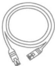
natural_image
Line drawing of a broadband cable with two connectors (no text or symbols)natural_image
Diagram of ceiling-mounted screw arrangement with upward arrows indicating direction (no text or symbols)
natural_image
Illustration of a hand using a power tool to test a device on a laptop screen (no text or symbols present)natural_image
Line drawing of a hand inserting a USB into a network device connected to a laptop (no text or symbols present)Accountgegevens invullen:
DynDNS.com
![Add New Hostname Note: You currently don't have any active Dynamic DNS Pro website in your account. You cannot use in features. Paying for an Dynamic DNS Pro upgrade will make the form fully functional and will add server to a new site. Hostname: - devdms.org Wildcard Status: Installed (Ward Wildcard support) Service Type: Host with IP address Webstep Redirect Offline Hostname If Address: see auto-detected IP address 90.75.16.44 T1 value is 60 seconds. Edit T1. Mail Setting: Yes, let me configure Email routing. [2] Add To Cart My Account My Services Dynamic DNS Pro Internet Guidis SLA Premier Support Some Level Services Server registry and Webpage, Webphone, Host Services Dynamic DNS Pro, Windows URL Pushing Spring Server IPS Walking Outbound Recessive DNS Network Monitoring SSL Certificates Review Services Auto Review Settings Sync Options Account Settings Billing My Cart Libxis](/content/2026/06/1272054/images/0eac690af34a07c79adee1c2d1aa2ede68a62350fb0c7c39755dfaa4199b1dfd.jpg)
Port Mapping activeren
Links: lage gevoeligheid.
Activeringstijd
Timing-snapshot activeren
natural_image
Exterior view of a white autonomous security camera (ABUS) with a spherical lens, shown against a plain background.natural_image
Line drawing of a mechanical component labeled 'ABUS' (no additional text or symbols)WLAN HD 720p indendørs domekamera med pan/tilt/zoom
natural_image
Line drawing of a cylindrical device with a coiled spring and a connector, labeled EU, AU, UK (no text or symbols on the device itself)
natural_image
Line drawing of a broadband cable with two connectors (no text or symbols)| Nr. | Beskrivelse |
| 1 | Objektiv |
| 2 | Mikrofon |
| 3 | WPS-tast & microSD-kort-slot |
natural_image
Diagram of ceiling-mounted screw arrangement with upward arrows indicating direction (no text or symbols)
natural_image
Illustration of a hand using a power tool to test a device on a laptop screen (no text or symbols present)natural_image
Illustration of a hand inserting a USB into a network device connected to a laptop (no text or symbols present)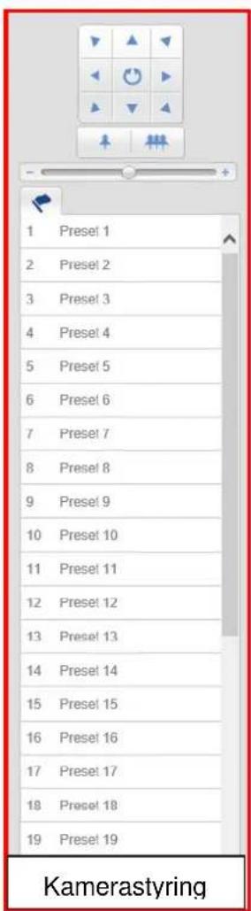
10.1. Menubjælke
Klik for at vælge den ønskede mappe "Livevisning", "Afspilning", "Konfiguration" eller "Protokol".
Gem konto-informationer:
DynDNS.com
natural_image
Exterior view of a white autonomous security camera (ABUS) with a spherical lens, shown against a plain background.Instrukcja obsługi
natural_image
Line drawing of a surveillance camera with no text or symbolsnatural_image
Line drawing of a cylindrical device with coiled spring and a connector, labeled EU, AU, UK (no text or symbols on the device itself)Zasilacz sieciowy
natural_image
Line drawing of a broadband cable with two connectors (no text or symbols)natural_image
Diagram of ceiling-mounted screw arrangement with upward arrows indicating direction (no text or symbols)
natural_image
Illustration of a hand using a power tool to test a component on a laptop screen (no text or symbols present)natural_image
Illustration of a hand inserting a USB into a network device connected to a laptop (no text or symbols present)Odbiorca1/Odbiorca2/Odbiorca3
natural_image
Exterior view of a white autonomous security camera (ABUS) with a spherical lens, shown against a plain background.natural_image
Line drawing of a surveillance camera with no text or symbols
natural_image
Line drawing of a cylindrical device with a coiled spring and a terminal connector, labeled EU, AU, UK (no text or symbols on the device itself)
natural_image
Line drawing of a broadband cable with two connectors (no text or symbols)natural_image
Diagram of ceiling-mounted screw arrangement with upward arrows indicating direction (no text or symbols)
natural_image
Illustration of a hand using a power tool to test a component on a laptop screen (no text or symbols present)natural_image
Line drawing of a hand inserting a USB into a network device connected to a laptop (no text or symbols present)natural_image
Exterior view of a white autonomous security camera (ABUS) with a spherical lens, shown against a plain background.natural_image
Line drawing of a surveillance camera with no text or symbolsnatural_image
Line drawing of a coiled spring device with no text or symbols on the diagram itself
natural_image
Line drawing of a broadband cable with two connectors (no text or symbols)natural_image
Diagram of ceiling-mounted screw and screw assembly with upward arrows indicating direction (no text or labels)
natural_image
Illustration of a hand using a probe to test a device on a laptop screen, with no visible text or symbols.natural_image
Illustration of a hand inserting a USB into a network device connected to a laptop (no text or symbols present)natural_image
Exterior view of a white autonomous security camera (ABUS) with a spherical lens, shown against a plain background.natural_image
Line drawing of a security camera with label 'AIDS' on top (no other text or symbols)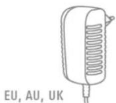
natural_image
Line drawing of a coiled spring device with labeled terminals EU, AU, UK (no text or symbols on the device itself)
natural_image
Line drawing of a broadband cable with two connectors (no text or symbols)natural_image
Diagram of ceiling-mounted screw arrangement with upward arrows indicating direction (no text or symbols)
natural_image
Illustration of a hand using a power tool to test a device on a laptop screen (no text or symbols present)natural_image
Illustration of a hand inserting a USB into a network device connected to a laptop (no text or symbols present)natural_image
Exterior view of a white autonomous security camera (ABUS) with a spherical lens, shown against a plain background.Bruksanvisning
natural_image
Line drawing of a mounted security camera with label 'AHUS' on top (no other text or symbols)natural_image
Line drawing of a cylindrical device with internal spring-like structure, labeled EU, AU, UK (no additional text or symbols)
natural_image
Line drawing of a broadband cable with two connectors (no text or symbols)natural_image
Diagram of ceiling-mounted screw arrangement with upward arrows indicating direction (no text or symbols)
natural_image
Illustration of a hand using a power tool to test a device on a laptop screen (no text or symbols present)natural_image
Line drawing of a hand inserting a USB into a network device connected to a laptop (no text or symbols present)NTP-servers IP-adress.
NTP-port
Lägga in kontoinformation:
DynDNS.com
![Add New Hostname Note: You currently don't have any active Dynamic DNS Pro updates in your account. You cannot use in features. Paying for an Dynamic DNS Pro upgrade will make the form fully functional and will add Severi Hostname: - dvdrms.org Wildcard Status: Insured/What Wildcard support! Service Type: ● Host with IP address [1] ○ Webstep Redirect [2] ○ Office Hostname [3] IP Address: see auto-detected IP address 90.75.16.44. [1] value is 60 seconds. Edit TTL. Mail Routing: □ Yes, let the configure Email routing. [2] Add to Cart My Account My Services Dynamic DNS Pro Internet Guide SLA Premier Support Zone Level Services Server registration and Sync Service Host Services Dynamic DNS Pro, Navigation URL Supporting Spring Server IPS Navigation Outbound Receive DNS Network Monitoring SSL Certificates Review Service Auto-New Settings Sync Excriptions Account Settings Billing My Cart Libers](/content/2026/06/1272054/images/e3e0674e9d11d6794e30312c30eee7be28ab279979e00620c482c6275af01f25.jpg)
These operating instructions are published by ABUS Security-Center GmbH & Co.KG, Linker Kreuthweg 5, 86444 Affing, Germany. No reproduction (including translation) is permitted in whole or part e.g. photocopy, microfilming or storage in electronic data processing equipment, without the express written consent of the publisher.
The operating instructions reflect the current technical specifications at the time of print.
We reserve the right to change the technical or physical specifications.

Note de l'éditeur
© Copyright 05/2014 by ABUS Security-Center
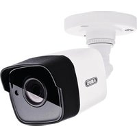
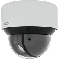
- TVIP41660
- Bedienungsanleitung
- Konto-Informationen hinterlegen:
- DynDNS.com
- Aktivierungszeit
- User manual
- Introduction
- Warning as required by §201 StGB (German Criminal Code):
- Disclaimer
- Explanation of symbols
- Important safety information
- Safety information
- Warnings
- Unpacking the device
- Contents
- Intended use
- Scope of delivery
- Features and functions
- Camera description
- Description of the connections
- Mounting/installation
- Mounting the camera
- IMPORTANT!
- Orientation of the camera
- Initial start-up
- Connecting the network camera directly to a PC/laptop
- Connecting the network camera to a router/switch
- Accessing the network camera for the first time
- Password prompt
- User functions
- Menu bar
- Live image display
- Audio/video control
- Camera control
- PTZ control
- Preset settings
- Playback
- Configuration
- Local Configuration
- Record File Settings
- Save record files to
- Save downloaded files to
- Image and Clip Settings
- Save snapshots in live view to
- Save snapshots during playback to
- Save clips to
- Basic Configuration
- Advanced configuration
- System
- Device Information
- Basic Information
- Device Name:
- Model:
- Serial No.:
- Firmware Version:
- Encoding Version:
- Number of Channels:
- Number of Alarm Input:
- Number of Alarm Output:
- Time Settings
- Time Zone
- Time Sync.
- NTP
- Server Address
- NTP Port
- Interval
- Manual Time Sync.
- Device Time
- Set Time
- Reboot
- Default
- Restore
- Import Config. File
- Config File
- Status
- Export Config. File
- Remote Upgrade
- Firmware
- DST
- DST
- Enable DST
- Start Time
- End Time
- DST Bias
- Network
- TCP/IP
- Select NIC:
- DHCP
- IPv4 Address
- IPv4 Subnet Mask
- IPv4 Default Gateway
- IPv6 Mode
- IPv6 Address
- IPv6 Subnet Mask
- IPv6 Default Gateway
- MAC Address
- MTU
- DNS Server
- Preferred DNS Server
- Alternative DNS Server
- Port
- HTTP Port
- RTSP Port
- HTTPS Port
- SDK Port (control port)
- DDNS
- DDNS
- Enable DDNS
- DDNS Type
- Domain
- Port
- User name
- Password
- Confirm
- Setting up a DDNS account
- Store your account information:
- Accessing the network camera via DDNS
- ABUS DDNS
- Wi-Fi
- Wireless List
- Wi-Fi
- SSID
- Network Mode
- Manage
- Ad-Hoc
- Security Mode
- Encryption Type:
- Key 1
- WPS
- Enable WPS
- PIN Code
- PBC Connection
- PIN code of the router
- UPnP TM
- Enable UPnP TM
- Friendly Name
- Port Mapping
- Enable Port Mapping
- Port Mapping Mode
- Protocol Name:
- HTTP
- RTSP
- Server Port (control port)
- External Port
- External IP Address
- Video/Audio
- Video
- Stream Type
- Video Type
- Resolution
- Bitrate Type
- Max. Bitrate
- Video Quality
- Frame Rate
- Video Encoding
- Audio
- Audio Encoding
- Audio Input
- Input volume
- Environmental noise filter
- PTZ
- Basic
- Basic Parameters
- Enable Proportional Pan
- Preset Speed
- Keyboard Control Speed
- PTZ OSD
- Zoom status
- PT Status
- Preset Status
- Power off memory
- Set Resume Time Point
- Initial Position
- Scheduled Tasks
- Clear configuration
- Image
- Display Settings
- Please note:
- Switch Day and Night
- Brightness
- Contrast
- Saturation
- Hue
- Sharpness
- Exposure Mode
- Exposure Time
- Day/Night Switch
- Auto
- Day
- Night
- Schedule
- Triggered by Alarm Input
- Sensitivity
- Filtering Time
- Smart IR
- BLC Area (Backlight Compensation)
- WDR
- White balance
- AWB1
- Locked WB
- Other
- Noise Reduction Level
- Mirror
- Rotate
- Video Standard
- OSD Settings
- Display Name
- Display Date
- Display Week
- Camera Name
- Time Format
- Date Format
- Display Mode
- OSD Size
- Text Overlay
- Privacy Mask
- Security
- User
- Level
- IP Address Filter
- Enable IP Address Filter
- IP Address Filter Type
- Basic Event
- Motion detection
- Area Settings
- Arming Schedule
- Link Method
- Other Linkage
- Alarm Input
- Alarm Input No.
- Alarm Name
- Alarm Type
- Linkage Method
- Send email:
- Notify Surveillance Centre
- Enable recording:
- Alarm Output
- Alarm Output No.
- Dwell Time
- Sender
- Sender's Address
- SMTP Server
- SMTP Port
- Enable SSL
- Attached Image
- Authentication
- Receiver
- Receiver1/Receiver2/Receiver3
- Receiver1's Address/Receiver2's Address/Receiver3's Address
- Snapshot
- Timing
- Enable Timing Snapshot
- Format
- Quality
- Event-Triggered
- Enable Event-Triggered Snapshot
- Capture Number
- Storage
- Recording plan
- Pre-record
- Post-record
- Enable Record Schedule
- choose between the following record types:
- Storage Management
- Percentage of Picture
- Percentage of Record
- Log
- Maintenance and cleaning
- Maintenance
- Cleaning
- Disposal
- GPL license information
- Accountgegevens invullen:
- Port Mapping activeren
- Activeringstijd
- Timing-snapshot activeren
- Menubjælke
- Gem konto-informationer:
- Instrukcja obsługi
- Odbiorca1/Odbiorca2/Odbiorca3
- Bruksanvisning
- NTP-port
- Note de l'éditeur
Brand : ABUS
Model : TVIP41660
Category : Surveillance Camera