
FUMO50020 - Security System ABUS - Free user manual and instructions
Find the device manual for free FUMO50020 ABUS in PDF.


| Product type | Optical smoke detector |
| Brand | ABUS |
| Model | FUMO50020 |
| Category | Security system |
| Dimensions (diameter) | 100 mm |
| Dimensions (height) | 50 mm |
| Weight | 150 g (without battery) |
| Power supply | 9V alkaline battery (included) |
| Battery life | Approximately 1 year |
| Main functions | Smoke detection, audible alarm (85 dB), LED indicator, test button |
| Sound indicator | Integrated siren ≥ 85 dB at 3 m |
| Visual indicator | Red flashing LED in alarm, green LED for normal operation |
| Button | Test/Silence |
| Installation | Ceiling mounting, fixing with screws and wall plugs supplied |
| Detection area | Up to 60 m² |
| Operating temperature | -10°C to +40°C |
| Humidity | Up to 95% non-condensing |
| Standards | CE, EN 14604 |
| Certification | VdS (optional) |
| Maintenance and cleaning | Dust with a vacuum cleaner or soft cloth every 6 months |
| Monthly test | Press the test button until the alarm sounds |
| Product lifespan | 10 years (expiration date indicated on the device) |
| Spare parts | 9V battery, mounting kit |
| Repairability | Not user-repairable; replace the device after 10 years |
| Warranty | 2 years |
Frequently Asked Questions - FUMO50020 ABUS
User questions about FUMO50020 ABUS
0 question about this device. Answer the ones you know or ask your own.
Ask a new question about this device
Download the instructions for your Security System in PDF format for free! Find your manual FUMO50020 - ABUS and take your electronic device back in hand. On this page are published all the documents necessary for the use of your device. FUMO50020 by ABUS.
USER MANUAL FUMO50020 ABUS
Installation Instructions (UK) 30
2WAY Module polyvelent
Instructions d'installation (FR).... 56
2WAY Modulo universale installabile
4.3 Platine

4.2 Housing interior 33
4.3 PCB 34
4.4 Keys 35
4.5 Dip switches 35
4.6 Jumpers 36
4.7 Internal piezo signaller 36
- INSTALLATION INSTRUCTIONS 37
5.1 Installation 37
5.2 Connecting the power supply 37
5.3 Connecting the inputs 38
5.4 Connecting the outputs 38
5.5 Connecting the siren 38
- PROGRAMMING 38
6.1 Starting programming 39
6.2 Menu items in the main menu 39
6.3 Selecting the functions on the WAM 39
6.3.1 WAM as wireless repeater 40
6.3.2 Wireless output module 41
6.3.3 Wireless transmitter/receiver 43
6.3.4 Wireless siren module 44
6.3.5 Wireless siren transmitter/receiver 45
6.3.6 Wireless reception module 47
6.3.7 Wireless cylinder receiver 51
6.4 Deleting wireless detectors 53
6.5 Signal strength measurement 53
6.6 Factory default setting 54
- TECHNICAL DATA 54
1. Preface
Dear customers, many thanks for your purchase of this wireless accessory module for the Secvest wireless alarm centre. ABUS Security-Center GmbH & Co. KG, hereby declares that the device with item number FUMO50020 complies with the essential requirements and other relevant provisions of Directive 1999/5/EG. The declaration of conformity can be obtained from the following address:
ABUS Security-Center GmbH & Co. KG Linker Kreuthweg 5 86444 Affing GERMANY"
To ensure proper and safe operation, it is your obligation to observe these installation instructions! In the event of questions, please contact your local specialist dealer.
2. Safety information
The accessory module is supplied with direct current from a 12 V power source (not included). A 6 V/1.2 Ah rechargeable battery supplies standby power in the event of an emergency (not included). The maximum power consumption of the connected components must not exceed 1 A at any time.
The device is designed for indoor use only. Humidity must not exceed 90% (non-condensed).
3. Features
The accessory module offers several functions in one device. When installing the unit, one of the following functions can be selected:
- Wireless repeater
• Wireless output module - Wireless transmitter/receiver
• Wireless siren module
• Wireless siren transmitter/receiver
• Wireless reception module
• Wireless cylinder receiver
A detailed description of the functions is found on the following pages of this manual.
The device must be fitted with a 6 V/1.2 Ah lead-gel rechargeable battery. This supplies emergency power to the transmitter/receiver and the processor in the event of a power failure of the primary 12 V power supply. Connected external power-consuming equipment is not supplied with power in the event of a power failure (e.g.
detectors). The LED display is also not supported in the event of a power failure.
4. Component names
4.1 Display
The LEDs on the accessory module light up depending on the event detected. The diagram gives an overview of the displayed events. The LEDs have the following meaning:

In addition to their use in standard operation, the LEDs also display the selected function during programming. Observe the notes on the respective function descriptions.
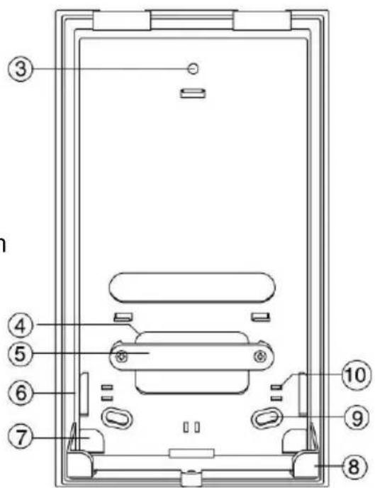
4.2 Housing interior
- Upper PCB holder
- Lower PCB holders
- Upper fixing hole
- Cable feed opening
- Plastic cable clamp bar (tension relief)
- Side cable feeds
- Corner cable feed
- Battery holder
- Lower fixing holes
- Cable clamps (tension relief)
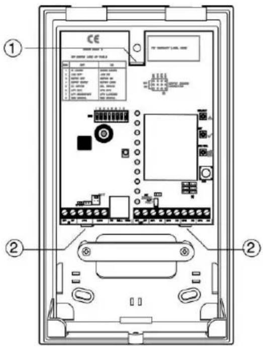

4.3 PCB

- DIP switches
- Piezo signaller
- IR LED receiver
- Battery connection
- Kickstart jumper connection
- Power supply connection and zone inputs
- RJ12 plug for external sirens
- Voltage output and relay output
- Fit disable jumper connection
- Jumper connections for output configuration
- Tamper contact
- ESC/DEL key
- SET key
- SELECT key
- Transmitter/receiver unit
- LED displays (detector channels)
4.4 Keys
The keys are required for programming and navigation in the programming menu. They have the following meanings:
SELECT: Press to start programming or to select another function during programming.
SET: Press to confirm the selected function during programming.
ESC/DEL: Press to end programming or to delete a selected function during programming.
4.5 Dip switches
Some dip switches have different meanings depending on the function of the accessory module. Some meanings are the same for all functions. They have the following meanings:
- OFF: The accessory module trains wireless transmitters via infrared LED only.
ON: The accessory module trains wireless transmitters via wireless protocol only.
- OFF: The accessory module does not monitor jamming.
ON: The accessory module transmits a fault message in the event of jamming. In function mode 6, relay 4 is activated in the event of malfunctions.
- OFF: The accessory module does not monitor the detectors for supervision.
ON: The accessory module transmits a fault in case of a supervision failure and sends a supervision message. In function mode 6, relay 4 is activated in the event of a supervision fault.
- OFF: Short supervision time (20 minutes).
ON: Long supervision time (3 hours).
- OFF: The inputs on the accessory module must be wired without a resistor (NC).
ON: The inputs of the accessory module must be wired with a 2.2 kΩ resistor (EOL).
- OFF: Input 1 of the accessory module works as an NC contact.
ON: Input 1 of the accessory module works as an NO contact.
- OFF: Input 1 works as an input for key switches (imp).
ON: Input 1 works as an input for magnetic contacts, motion sensors and block locks.
- See the notes on the dip switch position in the functional descriptions of the individual modes.
4.6 Jumpers
The accessory module is equipped with three different jumper connections, each of which have a different meaning. These meanings are as follows:
Kickstart: This jumper is positioned next to the battery plug connector.
If the accessory module is to be operated by battery only (e.g. for programming), plug in the jumper or short-circuit the connection with a screwdriver.
Fit disable: This jumper is positioned above the "O/P Fault" LED.
Plug in the jumper if the tamper contact on the rear is not used.
Outputs: These jumpers are positioned under the cover tamper contact.
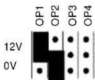
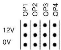
They regulate the output behaviour of the relay. The following sketch shows the possible settings and their meanings.

Output 1 becomes +12 V if activated.
Output 1 becomes 0 V if activated.
Output 1 works as relay contact.
Each output can be set individually.
4.7 Internal piezo signaller
The built-in piezo is used to support the programming of the accessory module. See the notes on the respective function. Additionally, the piezo can be activated for signal reception during the detector/function test.
5. Installation instructions
5.1 Installation
Proceed as follows when installing the accessory module:
Determine the best possible installation location. This should be selected so that good wireless communication between the components is guaranteed. We recommend using the wireless testing box for determining the installation location.
Note: Select the installation position so that the assembly module is positioned within the monitored range of a detector. Make sure that the accessory module is installed as high as possible – at least 1 metre above the ground.
The device must not be installed in the following locations:
- In protected or unprotected outdoor areas
- Within 1 metre of electronic equipment and lines, such as computers, photocopiers, LAN and high-voltage or three-phase voltage lines
After deciding on the place of installation, open the housing of the accessory module and first remove the PCB from the rear side by carefully bending the upper PCB holder upwards until the PCB can be removed.
Using the rear housing side as a template, mark the fixing holes on the wall. Fix the accessory module to the wall, but do not tighten the screws yet.
Connect the cables in the accessory module as shown on the following pages. Ensure sufficient tension relief for the cables in the accessory module.
Replace the PCB and tighten the screws.
Carry out the necessary programming (see point 7).
Following successful programming, the piezo signaller on the accessory module beeps at short intervals. Replace the cover at this point, then close the casing.
After about 5 seconds, the piezo signaller emits a double tone and confirms the programming. If the housing is opened again, a tamper alarm is sent to the wireless alarm system.
5.2 Connecting the power supply
This diagram shows the connection of the accessory module with the 12 V DC power supply.

5.3 Connecting the inputs
This diagram shows the connection of external alarm contacts to the accessory module. (for functions 3 and 5).

This diagram shows the connection of external alarm contacts with 2.2 kΩ terminal resistors to the accessory module (for functions 3 and 5).

5.4 Connecting the outputs
There are three different ways of connecting the outputs.
- OP1/0 V
Output OP1 becomes +12 V when activated.
- OP2/12 V
Output OP2 becomes 0 V when activated.
- OP4/C4

Use this connection type if the output is to be used as a relay (NO).
Note the different jumper positions.
5.5 Connecting the siren
The cable of the external siren is connected to the accessory module using the RJ12 plug. The cable is inserted into the RJ12 plug connector.

6. Programming
Program the WAM as follows: Firstly, connect the power supply to the accessory module (either via battery or via the 12 V PSU).
Program the function of the accessory module, and finally train the detectors to the module (or to the wireless alarm system). For some functions, it is also necessary to make individual settings over the programming mode on the wireless alarm system.
6.1 Starting programming
To start programming, proceed as follows:
- Make sure that the cover contact is open.
The green LED for power supply flashes (battery operation) or lights constantly (PSU). The red fault LED lights up. - Press SELECT.
LED number 1 also lights up blue. - You are now in programming mode.
6.2 Menu items in the main menu
The main menu contains the following menu items:
- Train detector -> LED 1 lights up.
- Delete detector -> LED 2 lights up.
- Select channel -> LED 3 lights up.
- Test signal strength -> LED 4 lights up.
- Set outputs -> LED 5 lights up.
- Not used
- Select function -> LED 7 lights up.
- Reset -> LED 8 lights up.
Press SELECT to change between menu items in programming mode. The display moves one menu item further with each key press and returns to the top after reaching the last item. The display of LED 6 is skipped here.
6.3 Selecting the functions on the WAM
The accessory module combines seven different functions, of which one must be allocated. To select a function, proceed as follows:
- From the main menu, press SELECT repeatedly until LED 7 lights up (select function).
- When LED 7 lights up, press SET once. You are now in the submenu of the menu item 7 (select function). LED 1 lights up.
- Press SELECT repeatedly until the LED of the desired function lights up.
Note: If you wish to allocate a new function to a programmed WAM, then all previously trained detectors are deleted.
6.3.1 WAM as wireless repeater
Function 1 / LED 1 (only in combination with the Secvest)
When programmed as a wireless repeater, the wireless module forwards the signals of up to eight wireless detectors to the Secvest. Ideally, it is installed halfway between the transmitter and receiver and can thus almost double the range between them. The transmitters (max. 8) must be trained for the accessory module and Secvest. Up to eight accessory modules can be operated as wireless repeaters with a wireless alarm system.
To program the accessory module as a wireless repeater, proceed as follows: Firstly, program the accessory module as a wireless repeater. Train the wireless detector to the accessory module and the receiver. Finally, you can train the accessory module to the wireless alarm system (optional).
- In the main programming menu, select item 7 (Function). LED 7 lights up.
Confirm by pressing SET.
In the submenu of item 7 (Function), select function 1 with the SELECT button. LED 1 lights up.
Confirm by pressing SET.
LED 7 lights up again.
Exit the programming mode by pressing ESC/DEL.
The LED for the power supply lights up/flashes and the fault LED lights up. The accessory module beeps at short intervals.
Close both tamper contacts of the WAM and wait until it emits a double tone.
-
Train the wireless detector to the wireless repeater, then the receiver. To train wireless detectors to the accessory module, proceed as follows:
-
Set dip switch 1 to ON.
- In the main programming menu, select item 1 (LED 1 lights up).
- Confirm by pressing SET.
- The LEDs show the state of the trained wireless detectors. If an LED flashes, this indicates that the channel is in use. If the LED is off, a detector can be trained in this channel.
- Trigger the tamper contact of the detector or send a signal from the detector. If the signal is received, the accessory module assigns this detector to a new channel. The LED of this channel starts to flash. The accessory module beeps twice when the detector has been successfully trained.
Note: When training a detector, consult the installation instructions of the detector. Magnetic contacts sometimes use two detector channels (reed contact and external contact).
- Repeat this process exactly to train other detectors.
- After all detectors have been trained, exit the programming mode by pressing ESC/DEL twice. Only the power supply LED lights up/flashes and the fault LED lights up. The accessory module beeps at short intervals.
Close both tamper contacts of the WAM and wait until it emits a double tone.
- If you want the wireless repeater to display the reception and forwarding of wireless signals using the LED of the detector channel, set dip switch 8 to ON. The LED of the respective channel now lights up every time a signal is received from this detector and forwarded.
- The WAM can also be trained as a wireless repeater in the wireless alarm system (optional). The advantage of this is that a function error in the detector or wireless repeater (battery/power failure, supervision failure or jamming) is transmitted to the wireless alarm system. A maximum of eight accessory modules can be trained as wireless repeaters in the Secvest.
To train the wireless repeater in the wireless alarm system, proceed as follows:
On the wireless alarm system, select "Add Other Devices/Wireless Accessory Module" and follow the installation instructions for the alarm system. When prompted, trigger the tamper contact of the accessory module and wait until the wireless alarm system receives the signal from the accessory module.
Set dip switch 3 of the accessory module to ON.
6.3.2 Wireless output module
Function 2 / LED 2 (only in combination with the Secvest)
If the accessory module is used as a wireless output module, it activates the four outputs (relay or transistor) when the corresponding programming is made or a corresponding event occurs. It is installed where a switch contact is required. The accessory module can perform this function in combination with the wireless alarm system, the remote control (FU5150/FU5155) or the emergency call transmitter. Up to eight accessory modules can be operated as wireless output modules with a wireless alarm system. To use the accessory module as a wireless output module, proceed as follows:
- In the main programming menu, select item 7 (Function). LED 7 lights up.
Confirm by pressing SET.
In the function submenu, select function 2 with the SELECT
button. LED 2 lights up.
Confirm by pressing SET.
LED 7 lights up again. Set dip switch 3 of the accessory module to ON.
Exit the programming mode by pressing ESC/DEL.
The LED for the power supply lights up/flashes and the fault LED lights up. The accessory module beeps at short intervals.
Close both tamper contacts of the WAM and wait until it emits a double tone.
- On the wireless alarm system, select "Add Other Devices/Wireless Accessory Module" and follow the installation instructions for the alarm system. When prompted, trigger the tamper contact of the accessory module and wait until the wireless alarm system receives the signal from the accessory module.
The accessory module is now trained as a wireless output module. This step is not necessary for stand-alone operation.
Remove all jumpers for controlling the outputs. To program the relay, follow the instructions in the wireless alarm system manual ("Programming outputs").
- The relay outputs can be programmed individually to work as NC instead of NO. Reprogramming relay outputs affects all function modes. To reprogram the relay channels, proceed as follows:
In the main programming menu, select item 5 (LED 5 lights up).
Confirm by pressing SET.
LED 1 lights up or flashes to show output 1.
You are now in the submenu of item 5. Select the output where the polarity is to be changed. To select the output, press SELECT.
Confirm the selection of the output by pressing SET.
The LED of the selected output flashes or lights up.
To change the polarity of the output, press SELECT.
A constantly lit LED means that this output is programmed as NO.
A flashing LED means that this output is programmed as NC.
After setting the polarity of the output, confirm the selection by pressing SET.
You now return to the output selection menu.
After setting the outputs, exit the programming mode by pressing ESC/DEL.
The LED for the power supply lights up/flashes and the fault LED lights up. The accessory module beeps at short intervals.
Close both tamper contacts of the WAM and wait until it emits a double tone.
- Connect the outputs with their switch contacts accordingly. Note that the switching power of the relay is max. 500 mA at 12 V DC! In the default setting, the relay contact works as a NO contact.
After completing all connections, close the accessory module.
If an output is activated, the LED of the output lights as long as the output is active. This function is only active if the accessory module is supplied with 12 V DC power.
6.3.3 Wireless transmitter/receiver
Function 3 / LED 3 (only in combination with the Secvest)
When used as a wireless transmitter or receiver, the accessory module has four relay outputs and two alarm inputs. Alarm input 1 is used for connecting an alarm contact for external detectors. Alarm input 2 is used for connecting a tamper line. The accessory module can only carry out this function in combination with the wireless alarm system. Up to eight accessory modules can be operated as wireless transmitters/receivers with the Secvest.
This function works in the same way as function 2 (see “Wireless output module” above). However, both inputs are additionally active on the accessory module. To use the accessory module as a wireless transmitter/receiver, proceed as follows:
- In the main programming menu, select item 7 (Function). LED 7 lights up.
Confirm by pressing SET.
In the submenu of item 7 (Function), select function 3 with the SELECT button. LED 3 lights up.
Confirm by pressing SET. LED 7 lights up again.
Set dip switch 3 of the accessory module to ON.
Exit the programming mode by pressing ESC/DEL.
The LED for the power supply lights up/flashes and the fault LED lights up. The accessory module beeps at short intervals.
Close both tamper contacts of the WAM and wait until it emits a double tone.
- On the wireless alarm system, select "Add Other Devices/Wireless Accessory Module" and follow the installation instructions for the alarm system. When prompted, trigger the tamper contact of the accessory module and wait until the wireless alarm system receives the signal from the accessory module.
The accessory module is now trained as a wireless transmitter/receiver.
The outputs behave in the same way as the wireless output module (see 7.3.2).
Connect the inputs with the accessory module. Input 1 is used for connecting the alarm contact for detectors. Alarm input 2 is used for connecting the tamper line for detectors.
Set dip switches 5, 6 and 7 according to the input connection and then close the housing on the accessory module.
Program the outputs in your wireless alarm system (see the corresponding instructions).
6.3.4 Wireless siren module
Function 4 / LED 4 (only in combination with the Secvest)
When used as a wireless siren module, the accessory module is used to trigger an external signalling device. This function can only be used if the accessory module is combined with the wireless alarm system. The signalling device is connected to the accessory module with a six-pin cable (supplied with the signalling device).
To use the accessory module as a wireless siren module, proceed as follows:
- In the main programming menu, select item 7 (Function). LED 7 lights up.
Confirm by pressing SET.
In the submenu of item 7 (Function), select function 4 with the SELECT button. LED 4 lights up.
Confirm by pressing SET.
LED 7 lights up again.
Set dip switch 3 of the accessory module to ON.
Exit the programming mode by pressing ESC/DEL.
Only the power supply LED lights up/flashes and the fault LED lights up. The accessory module beeps at short intervals.
Close both tamper contacts of the WAM and wait until it emits a double tone.
- On the wireless alarm system, select "Add Other Devices/Wireless Accessory Module" and follow the installation instructions for the alarm system. When prompted, trigger the tamper contact of the accessory module and wait until the wireless alarm system receives the signal from the accessory module.
The accessory module is now trained as a wireless siren module. No further programming is required.
Connect the cable of the siren to the RJ12 plug on the accessory module. Alternatively, follow the instructions below on connecting conventional sirens.
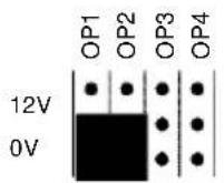
Note: When the siren is connected via the RJ12 plug on the accessory module, jumpers 1 and 2 must be plugged as follows:
Dip switch 8 must be set to OFF.
Program the behaviour of this siren in the wireless alarm system under the following points:
• Partitions for acknowledge functions
• Editing WAM for alarm functions
3. Connecting a conventional siren
If the accessory module is used in function 4 (wireless siren module) and a conventional siren should be used without its own power supply, connect the accessory module with the siren as follows:

6.3.5 Wireless siren transmitter/receiver
Function 5 / LED 5
When used as a wireless siren transmitter or receiver, a wireless siren can be connected to any centre over the accessory module. The inputs of the accessory module are connected to the alarm centre relay outputs used for triggering the flash and siren. The outputs of the accessory module are connected to the tamper input of the alarm centre. A further accessory module is connected to any signalling device. The flash and siren can be triggered wirelessly and independently of each other.
To use the accessory modules as wireless siren transmitters/receivers, proceed as follows:
Firstly, program the accessory module connected to a siren as a
wireless siren module (see section 7.3.4).
Note: Instead of training the accessory module to the wireless alarm system, it is trained to the second accessory module.
Only then program the second accessory module connected to the alarm system. Do this as follows:
- In the main programming menu, select item 7 (Function). LED 7 lights up.
Confirm by pressing SET.
In the submenu of item 7 (Function), select function 5 with the SELECT button. LED 5 lights up.
Confirm by pressing SET.
LED 7 lights up again.
- In the main menu of the accessory module, select item 1 (Train detector). LED 1 lights up.
Trigger the tamper contact on the accessory module that works as a wireless siren module and is connected to the siren.
When the accessory module working as a wireless siren transmitter/receiver has received the signal, the blue LEDs 1-3 flash on the module.
Exit the programming mode by pressing ESC/DEL.
The LED for the power supply lights up/flashes and the fault LED lights up. The accessory module beeps at short intervals.
Close both tamper contacts of the WAM and wait until it emits a double tone.
The accessory module is now trained as a wireless siren transmitter/receiver. When the input 1 (2) is closed, output 1 (2) on the other accessory module (connected with the siren) is activated.
- Connect the accessory module with the alarm centre as illustrated.

TR is the sabotage input of the alarm centre.
On the alarm system, program output 1 to after a siren (NO) and output 2 to after a flash (NO).
The jumpers are allocated as shown here:

6.3.6 Wireless reception module
Function 6 / LED 6
When used as a wireless reception module, a connected system can be expanded by up to eight wireless components per module using the accessory module. The accessory module serves as a wireless receiver for these eight wireless detectors. The relay outputs are connected to the zone inputs of the connected centres. In addition to alarms, tamper and detector faults are also transmitted (battery fault, supervision failure, jamming etc.). Each of four wireless detectors activate one relay output. All tamper messages activate the third relay output; whilst fault messages activate the fourth relay output.
To use the accessory module as a wireless receiver module, proceed as follows:
- Select the appropriate switch position for dip switches 2, 3 and 4 (see point 5.5).
In the main programming menu, select item 7 (Function). LED 7 lights up.
Confirm by pressing SET.
In the submenu of item 7 (Function), select function 6 with the SELECT button.
LED 6 lights up.
Confirm by pressing SET.
LED 7 lights up again.
Exit the programming mode by pressing ESC/DEL.
The LED for the power supply lights up/flashes and the fault LED lights up. The accessory module beeps at short intervals.
Close both tamper contacts of the WAM and wait until it emits a double tone.
- Train the wireless detector to the WAM.
To do this, proceed as follows:
- Set dip switch 1 to ON.
- In the main programming menu, select item 1 (LED 1 lights up).
- Confirm by pressing SET.
- The LEDs show the state of the trained wireless detectors.
If an LED flashes, this indicates that the channel is in use. If the LED is off, a detector can be trained in this channel.
- Trigger the tamper contact of the detector or send a signal from the detector. If the signal is received, the accessory module assigns this detector to a new channel. The LED of this channel starts to flash. The accessory module beeps twice when the detector has been successfully trained.
Note: When training a detector, consult the installation instructions of the detector. Magnetic contacts sometimes use two detector channels (reed contact and external contact).
- Repeat this process exactly to train other detectors.
- After all detectors have been trained, exit the programming mode by pressing ESC/DEL twice. Only the power supply LED lights up/flashes and the fault LED lights up. The accessory module beeps at short intervals.
Close both tamper contacts of the WAM and wait until it emits a double tone.
- Remove all jumpers for controlling the outputs and connect the accessory module to the alarm centre as described in the following example.
The relay outputs are activated if a detector triggers. The detector allocation can be seen in the table below. Four detectors are assigned to each relay output. This relay output is activated as soon as a detector has been triggered.
If a remote control (FU5150/FU5155) has been changed, only key 4 of the remote control is active (marked with a square) and can control a relay output. To use a remote control for activation/deactivation, it should be programmed for its own output.
| Output 1 | Wireless detector 1 | Wireless detector 2 | Wireless detector 3 | Wireless detector 4 |
| Output 2 | Wireless detector 5 | Wireless detector 6 | Wireless detector 7 | Wireless detector 8 |
| Output 3 | Tamper message of all trained wireless detectors | |||
| Output 4 | Fault message of all trained wireless detectors (battery loss, jamming, supervision failure) | |||
| Input 1 | First detector recognition (close input to activate function) | |||
| Input 2 | Walk test function (close input to activate function) | |||
Connection example of an accessory module to a connected alarm system, e.g.: Terxon S. Note that the jumpers are all removed and the outputs are working as relays (NC).
Inverting relay outputs
You can reprogram the relay outputs individually to work as NC instead of NO. Reprogramming relay outputs affects all function modes. To reprogram the relay channels, proceed as follows:
In the main programming menu, select item 5 (LED 5 lights up).
Confirm by pressing SET.
LED 1 lights up or flashes to show output 1.
You are now in the submenu of item 5. Select the output where the polarity is to be changed. To select the output, press SELECT.
Confirm the selection of the output by pressing SET.
The LED of the selected output flashes or lights up.
To change the polarity of the output, press SELECT.
A constantly lit LED means that this output is programmed as NO. A flashing LED means that this output is programmed as NC.
After setting the polarity of the output, confirm the selection by pressing SET. You now return to the output selection menu.
After setting the outputs, exit the programming mode by pressing ESC/DEL.
The LED for the power supply lights up/flashes and the fault LED lights up. The accessory module beeps at short intervals.
Close both tamper contacts of the WAM and wait until it emits a double tone.
In this example, dip switches 2, 3 and 4 of the accessory module are set to ON. Battery faults, supervision failure and jamming all activate output 4 of the WAM.
First-detector recognition:
Output 1 of the alarm centre is connected to input 1 of the accessory module. If the alarm centre is activated, this output switches against ground (0 V) and remains so until the system is deactivated.
After the alarm centre is deactivated, the LED of the detector channel that was triggered first flashes on the accessory module. LEDs on detector channels that have also triggered light constantly on the accessory module.
Walk test:
Output 2 of the alarm centre is connected to input 2 of the accessory module. If a walk test is to be conducted, output 2 of the alarm centre switches against ground (0 V). Trigger all wireless detectors in succession. When the accessory module receives the signal, reception is acknowledged with an acoustic signal tone. The LED of the detector channel on the accessory module is lit constantly. After testing all detectors, deactivate output 2 of the alarm centre. The LEDs now go out.

Special function of detector channels in function mode 6
This function only has an effect on the function of trained remote controls (FU5150/FU5155) in function mode 6. In all other function modes, the setting made here is ignored. The setting influences the detector channels in their trigger function for the relay outputs assigned to them as permanent or pulse contact. To reprogram the detector channels, proceed as follows:
In the main programming menu, select item 3 (LED 3 lights up).
Confirm by pressing SET. LED 1 lights up or flashes to show output 1.
You are now in the submenu of menu item 3. Select the
detector channel whose attributes you want to change. To select the detector channel, press SELECT.
Note: Detector channels 1-4 affect the function of relay output 1, whilst detector channels 5-8 affect the function of relay output 2.
Confirm the selection of the detector channel by pressing SET. The LED of the selected detector channel flashes or lights up.
To change the attribute of the detector channel, press SELECT. A constantly lit LED means that this output is programmed as a permanent contact. A flashing LED means that this output is programmed as a pulse contact.
After setting the attribute of the detector channel, confirm the selection by pressing SET. You now return to the detector channels selection menu.
After making settings for the detector channels, exit programming mode by pressing ESC/DEL.
The LED for the power supply lights up/flashes and the fault LED lights up. The accessory module beeps at short intervals.
Close both tamper contacts of the WAM and wait until it emits a double tone.
If the channel is programmed as a permanent contact, activate the output by pressing button 4 (square) and deactivate it by pressing button 3 (hash). If more than one remote control was trained, then the deactivation command must be received from every remote control in order to deactivate the output.
6.3.7 Wireless cylinder receiver
Function 7 / LED 7
When used as a wireless cylinder receiver, a connected system can also be activated and deactivated with the wireless cylinder using the accessory module. The accessory module works as a block lock. There are two modes here. In mode one, two cylinders control a relay. In mode two, four cylinders control a relay.
To use the accessory module as a wireless cylinder receiver, proceed as follows:
- Set the position of dip switch 1 to ON and all others to OFF. More information on the position of dip switch 8 can be seen below.
In the main programming menu, select item 7 (Function). LED 7 lights up.
Confirm by pressing SET.
In the submenu of item 7 (Function), select function 7 with the SELECT button. LED 7 lights up.
Confirm by pressing SET.
LED 7 lights up again.
Exit the programming mode by pressing ESC/DEL.
The LED for the power supply lights up/flashes and the fault LED lights up. The accessory module beeps at short intervals.
Close both tamper contacts of the WAM and wait until it emits a double tone.
Note: In order to train the wireless cylinder to the accessory module, the dip switch 1 must be set to ON.
- To train the wireless cylinder to the accessory module, proceed as follows:
Set dip switch 1 to ON.
In the main programming menu, select item 1 (LED 1 lights up).
Confirm by pressing SET.
The LEDs show the state of the trained wireless detectors. If an LED flashes, this indicates that the channel is in use. If the LED is off, a detector can be trained in this channel.
Send a signal from the cylinder. If the signal is received, the accessory module assigns this detector to a new channel. The LED of this channel starts to flash. When the signal has been successfully trained, the accessory module beeps twice.
Repeat the steps above to train another cylinder.
After training all detectors, exit programming mode by pressing ESC/DEL twice.
The LED for the power supply lights up/flashes and the fault LED lights up. The accessory module beeps at short intervals.
Close both tamper contacts of the WAM and wait until it emits a double tone.
- Remove all jumpers for controlling the outputs and connect the accessory module to the alarm centre as described under point 7.3.6.
The relay outputs are opened when the wireless cylinder is rotated in the close direction and the alarm system is activated. The relay outputs are closed when the wireless cylinder is rotated in the open direction and the alarm system is deactivated.
Note: Invert the outputs as detailed under point 7.3.6.
The outputs are stable when switched, meaning the zone of the centre must be programmed as a block lock.
In mode 1 with dip switch 8 set to OFF, the detector channels are each allocated to an output in pairs. This means that channels 1 and 2 control output 1, channels 3 and 4 control output 2 and so on.
In mode 2 with dip switch 8 set to ON, four detector channels are allocated to an output. This means that channels 1, 2, 3 and 4 control output 1 and channels 5, 6, 7 and 8 control output 2. The other outputs have no function.
6.4 Deleting wireless detectors
Wireless detectors can be deleted individually from the accessory module. To delete wireless detectors from the accessory module, proceed as follows:
In the main programming menu, select item 2 (LED 2 lights up).
Confirm by pressing SET.
The LEDs show the state of the trained wireless detectors. If an LED flashes, this indicates that a wireless detector is trained for this channel.
Press SELECT to switch between the channels.
To delete a wireless detector, select the corresponding channel and then press ESC/DEL. Keep this button pressed until the accessory module beeps twice.
LED 2 lights up to indicate that you are in step 2 of the programming mode.
To delete another wireless detector, press SET again. The LED of an occupied channel flashes again.
Repeat step 5. When all detectors are deleted, item 2 of the main menu can no longer be accessed. In this case, the accessory module emits a double tone.
After deleting the detectors, exit the programming mode by pressing ESC/DEL.
Only the power supply LED lights up/flashes and the fault LED lights up. The accessory module beeps at short intervals.
Close both tamper contacts of the WAM and wait until it emits a double tone.
6.5 Signal strength measurement
The accessory module can measure the signal strength of trained wireless detectors and display it on the LEDs. To measure the signal strength of trained wireless detectors, proceed as follows:
In the main programming menu, select item 4 (LED 4 lights up).
Confirm by pressing SET.
Note: A detector test can only be made when at least one wireless detector has been trained. If no detectors have been trained, a double tone sounds.
Trigger a detector. After the signal is received, the signal strength can be determined according to the number of blue LEDs. At least three blue LEDs must light up for sufficient wireless communication.
After testing the detectors, exit the programming mode by pressing ESC/DEL.
Only the power supply LED lights up/flashes and the fault LED lights up. The accessory module beeps at short intervals.
Close both tamper contacts of the WAM and wait until it emits a double tone.
6.6 Factory default setting
To delete all settings in the accessory module and all detectors, proceed as follows:
In the main programming menu, select item 8 (LED 8 lights up).
Confirm by pressing SET.
All LEDs flash.
Keep ESC/DEL pressed until the accessory module emits a double tone as confirmation and LED 8 lights up. The programming and all trained wireless detectors are now deleted.
Note: To exit menu item 8 without making a factory reset, only press ESC/DEL briefly.
After restoring the factory default settings, exit the programming mode by pressing ESC/DEL.
The LED for the power supply lights up/flashes and the fault LED lights up. The accessory module beeps at short intervals.
Close both tamper contacts of the WAM and wait until it emits a double tone.
7. Technical data
Power supply: 12 V DC
Power consumption: 70 mA when idle
90 mA with activated relay
240 mA with activated relay and
battery charge
Emergency power supply: 6 V DC, 1.2 Ah
Number of channels: 8
Display: 10 LEDs
Outputs: 4 x transistor relays (NO/NC)
Max. switching power 500 mA,
24 V DC, R = 2 Ω
1 x RJ12 for triggering the sirens
Inputs: 2
Compatibility: Secvest
Terxon LX
Terxon MX
Terxon SX
Wireless smoke detector
Wireless motion sensor
Wireless magnetic contact
Wireless vibration detector
Wireless glass breakage detector
Remote control (FU5150/FU5155)
Wireless cylinder (SecvestKey)
Wireless emergency call button (medical emergencies or panic alarm)
External wireless siren
Dimensions:
220 x 135 x 42 mm (HxWxD)
Weight:
330 g (without rechargeable battery)
ABUS Security-Center GmbH & Co. KG, hereby declares that the device with item number FUMO50020 complies with the essential requirements and other relevant provisions of Directive 1999/5/EG. The declaration of conformity can be obtained from the following address:
The functionality of the accessory has enlarged. Affected are the mode repeater, wireless output module, wireless siren module and wireless reception module.
Wireless repeater
In function 1 there are additional transmitters possible which will be repeated
• FU59xx/FUSK5xxxxx 2WAY Secvest Key
• FU8100/FUBE50000 2WAY Wireless remote control
• FU8110/FUBE50011/12 2WAY Wireless keypad
• FU8165/FUBE50060Wireless key-switch
• FU8200/FUMO50030 Wireless Info Module (also FU5200)
• FU822X/FUSG50000 Wireless outdoor sounder
• FU8230/FUSG50010 Wireless indoor siren
• FU8130/FU8140/FUFT50010/20 Wireless additional door lock
The wireless repeater is of course downward compatible to all devices
Wireless Output Module
In function 2 now are maximal 4 channels possible. A List of the supported devices sees below.
| IR | Radio | ||
| FU5140 | No | No | |
| FU5150, FU5155, FU8150Uses channel 1-4, no more channels available. OP1-Triangle, OP2-Diamond, OP3-Circle, OP4-Square | Yes | Yes | |
| FU56xxUses channel 1-4, no more channels available. OP2-deaktiv (Diamond), OP4-aktiv (Square) OP1 and 3 without function. | No | Yes | |
| FU59xx/FUSK5xxxxx 2WAY Secvest Key FU8130/FU8140/FUFT50010/20 Wireless | No | No | |
| FU8100/FUBE50000, FU8110/FUBE50011/12 | No | No | |
| FU8165/FU5165/FUBE50060 | No | No | |
| FU8200/FUMO50030, FU5200 | No | No | |
| FU8220, FU8230/FUSG50010 | No | No | |
| FU8300/FUAT50010, FU8310/FUAT50020Uses 2 channels | Yes | Yes | |
| FU8305Uses 1 channel | Yes | Yes | |
| FU8320/1/FUMK50000/10, FU5120 / FU5121, FU8430/5Uses 2 channels (Reed contact+tamper or Alert +tamper ext. contact)OP1=Alert, OP2=Tamper or OP3= Alert,OP4=Tamper. Also can be 2+3 | Yes | Yes | |
| FU8330/FUWM50000OP1=Alert, OP2=Tamper or OP3= Alert,OP4=Tamper. Also can be 2+3. | Yes | Yes | |
| FU8340/FURM50000Uses 2 channels. Only the “alert channel” will respond no tamper exists.OP is permanent switched, have to be reset through e.g. manually switching in user menu!!! | Yes | Yes | |
| FU8350/FUBW50000, FU8370/FUGB50000, FU8380/FUEM50000, FU5110OP1=Alert, OP2=Tamper or OP3= Alert,OP4=Tamper. Also can be 2+3 | Yes | Yes | |
| FU8390/FUAT50000Uses 1 channel | Yes | Yes | |
| FU84xx FTSE 96, FU8420 / FU8421 / FU8422FU8130/FU8140/FUFT50010/20OP1=Alert, OP2=Tamper or OP3= Alert,OP4=Tamper. Also can be 2+3No distinction between cullet lever and the alarm bit always is sent. | Yes | Yes |
Wireless siren module
The Function 4 works with a wired si
Please refer to page 44 of the manual.
The chart on page 48 of the manual can used analogue.
Please notice: The LED's won't light if messages will be received.
Wireless reception Module
In function 6 now further components can be used.
Please notice: The LED's won't light if messages will be received.
The behavior of the outputs concerning to the different components is show in the list above.
| IR | Funk | |
| FU5150, FU5155, FU8150Uses 1 ChannelWith menu 3 analogous detector channel → ImpulseSquare switches OP1 or OP2, due to impulse OP switches backDiamond without functionWith menu 3 analogous detector channel → LatchSquare switches OP1 or OP2 o Diamond switches back | Yes | Yes |
| FU56xx Secvest Key old (works as FU5155) Button 1 (analog Triangle)=Active Button4(analog Diamond)=Deictic | No | Yes |
| FU8220, FU8230/FUSG50010, FU8200/FUMO50030 (and FU5200) | n/a | n/a |
| FU8300/FUAT50010, FU8310/FUAT50020, FU8320/21/25, FU8330/FUWM50000, FU8350/FUBW50000, FU5110, FU8360/FUBW50010, FU8430/35/FUFT50040OP1 or OP2=AlertOP3=Tamper | Yes | Yes |
| FU8305OP1 or OP2=Alert | Yes | Yes |
| OP4= Battery fault, Jamming, Supervision | |||
| FU8340/FURM50000OP1 or OP2=AlertOP4= Battery fault, Jamming, Supervision | Yes | Yes | |
| FU8370/FUGB50000OP1 or OP2=AlertOP4= Battery fault, Jamming, Supervision | Yes | Yes | |
| FU8380/FUEM50000OP1 or OP2=AlertOutput only switches back Channels if is set to impulseDetector doesn't send a restoreOP4= Battery fault, Jamming, Supervision | Yes | Yes | |
| FU8390/FUAT50000OP1 or OP2=AlertOP4= Battery fault, Jamming, Supervision | Yes | Yes | |
| FU84xx FTSE 96, FU8420 / FU8421 / FU8422FU8130/FU8140/FUFT50010/20OP1 or OP2=AlertOP3=TamperOP4= Battery fault, Jamming, SupervisionNo distinction between cullet lever, but the alarm bit always is sent. | Yes | Yes | |
Contenu
-
PREFACE 57
-
CONSIGNES DE SECURITE 57
-
CARACTERISTIQUES 57
-
DESIGNATION DES COMPOSANTS 58
4.1 Afficheur 58
4.3 Platine

Security Tech Germany
Security Tech Germany
4.3 Scheda

4.3 Printplaat

Stroomopname: 70 mA in rust
Security Tech Germany
4.3 Printkort

ON: Lang supervisionstid (3 timer).



- 2WAY Module polyvelent
- 2WAY Modulo universale installabile
- Preface
- Safety information
- Features
- Component names
- Display
- Housing interior
- Keys
- Dip switches
- Jumpers
- Internal piezo signaller
- Installation instructions
- Installation
- Connecting the power supply
- Connecting the inputs
- Connecting the outputs
- Connecting the siren
- Programming
- Starting programming
- Menu items in the main menu
- Selecting the functions on the WAM
- WAM as wireless repeater
- Wireless output module
- Wireless transmitter/receiver
- Wireless siren module
- Connecting a conventional siren
- Wireless siren transmitter/receiver
- Function 5 / LED 5
- Wireless reception module
- Walk test:
- Wireless cylinder receiver
- Deleting wireless detectors
- Signal strength measurement
- Factory default setting
- Technical data
- Wireless repeater
- Wireless Output Module
- Wireless siren module
- Wireless reception Module
- Contenu
- Platine
- Security Tech Germany
- Scheda
- Printplaat
- Printkort
Brand : ABUS
Model : FUMO50020
Category : Security System