
IR Link Pro Flush - Remote control EBODE - Free user manual and instructions
Find the device manual for free IR Link Pro Flush EBODE in PDF.


| Type de produit | Flush-mount infrared repeater |
| Marque | ebode |
| Modèle | IR Link Pro Flush |
| Dimensions (L x l x H) | 50 x 50 x 20 mm |
| Poids | 50 g |
| Alimentation | 3 V battery (CR2032) or 5 V USB power adapter |
| Portée infrarouge | Up to 30 meters line of sight |
| Fréquence IR | 38 kHz |
| Compatibilité | TV, Hi-Fi system, decoder, etc. |
| Installation | Flush or surface mount |
| Câble | 1.5 m cable between transmitter and receiver |
| Matériau | ABS plastic |
| Entretien et nettoyage | Wipe with a soft, dry cloth |
| Sécurité | Do not immerse in water. Disconnect before cleaning. |
| Pièces détachées | Not available separately |
| Réparabilité | Not user repairable |
| Contenu de l'emballage | Transmitter, receiver, cable, CR2032 battery, power adapter |
| Garantie | 2 years |
Frequently Asked Questions - IR Link Pro Flush EBODE
User questions about IR Link Pro Flush EBODE
0 question about this device. Answer the ones you know or ask your own.
Ask a new question about this device
Download the instructions for your Remote control in PDF format for free! Find your manual IR Link Pro Flush - EBODE and take your electronic device back in hand. On this page are published all the documents necessary for the use of your device. IR Link Pro Flush by EBODE.
USER MANUAL IR Link Pro Flush EBODE
natural_image
Close-up of a brass cylindrical sensor component with a black cable, no visible text or symbolsIR Link Series – Extend your remote!
IR Link Pro Flush – Mains Powered IR Remote Control Extender

User guide 3

1x IRLPRO IR Link Pro Flush Mount Receiver, including 4 interchangeable coloured top covers,
1x IRHUB4 Connecting Hub + Status input Jumper Cable,
2x 3IREDB Triple Blinking Emitter, including replacement adhesives
1x IRQC Quick Connect cable
1x 230V\~50Hz to 12VDC 200mA Power Supply Adapter.
Example of where to install your IR Link Pro Flush:

natural_image
Pure electrical circuit lines without any symbols
flowchart
graph TD
    A["TV"] -->|status LED\nfeedback LED| B["IR"]
    B --> C["PSU 230V~50Hz"]
    C --> D["DVR"]
    C --> E["STB"]
    C --> F["AUX"]
    D --> G["3REDIE (2x)\nROC"]
    E --> G
    F --> G
    style A fill:#f9f,stroke:#333
    style B fill:#ccf,stroke:#333
    style C fill:#cfc,stroke:#333
    style D fill:#fcc,stroke:#333
    style E fill:#fcc,stroke:#333
    style F fill:#fcc,stroke:#333
    style G fill:#cff,stroke:#333
CONTENTS
- Conformity of Use
- Introduction
- Kit content
- How does the ebode IR Link Pro Flush work?
- Installing the ebode IR Link Pro Flush
- Operation
- How to avoid and solve possible problems
- Technical information
1. Conformity of Use
For carefree and safe use of this product, please read this manual and safety information carefully and follow the instructions. The unit is registered as a device that does not cause or suffer from radio-frequency interference. It is CE approved and it conforms with the Low Voltage Directory. The safety and installation instructions must be observed. Technical manipulation of the product or any changes to the product are forbidden, due to security and approval issues. Please take care to set up the device correctly - consult your user guide. Young children should use the device only under adult supervision. No guarantee or liability will be accepted for any damage caused due to incorrect use of the equipment supplied, other than indicated in this owner's manual.
SAFETY WARNINGS
- To prevent short circuits, this product (except if specified for outdoor use) should only be used inside and only in dry spaces. Do not expose the components to rain or humidity.
- Avoid strong mechanical tear and wear, extreme ambient temperatures, strong vibrations and atmospheric humidity.
- Do not disassemble any part of the product: no user-serviceable parts are inside. The product should only be repaired or serviced by qualified and authorized service personnel. Defected pieces must be replaced by original (spare) parts.
- Batteries: keep batteries out of the reach of children. Dispose of batteries as chemical waste. Never use old and new batteries or different types of batteries together. Remove the batteries when you are not using the system for a longer period of time. When inserting batteries be sure the polarity is respected. Make sure that the batteries are not short circuited and are not disposed in fire (danger of explosion).
In case of improper use or if you have opened, altered and repaired the product yourself, all guarantees expire. The supplier does not accept responsibility in the case of improper use of the product or when the product is used for purposes other than specified. The supplier does not accept responsibility for additional damage other than covered by the legal product responsibility.
2. Introduction
Congratulations on purchasing the ebode IR Link Pro Flush Kit. Our ebode proprietary eIR 2x™ (pronounce Irex) Technology guarantees a high level of immunity for InfraRed noise from direct sunlight, CFL lighting and Flat Panel TV's (including Plasma, LCD and LED).
This kit contains two 3IREDB Triple Blinking Emitters for control of 6 devices, and a 1IRQC Quick Connect cable for direct control of popular Audio/Video Receivers (e.g. Yamaha, Onkyo, Denon, Marantz, NAD, Harman Kardon, Pioneer, Sony etc). The IR Link Pro Flush Kit runs on a 12VDC mains adapter (included) and is expandable with extra IR Link Receivers in different rooms.
The IR Link Pro Flush Kit is a mains powered InfraRed Extender System that allows full remote control operation of audio/video components (such as your Blu-ray player, A/V Receiver, DVR, Satellite Box, Cable Tuner, etc.) which are located behind closed cabinet doors, in other rooms, or other concealed and/or out-of-sight locations.
An InfraRed Extender in general consists of an IR (InfraRed) capture device, the IR Receiver, a distribution circuit/connecting block, the IR Hub, and finally the IR LED output, the IR Emitter, which flashes the IR signal to the A/V component.
3. Kit content
The IR Link Pro Flush Kit is a pre-packaged InfraRed Remote Control Extender System. It includes an IRLPRO Flush Mount IR Receiver with 4 interchangeable, coloured top covers (black, white, brushed chrome and brass), an IRHUB4 Connecting Hub with 4 Emitter outputs + Status input Jumper Cable, two 3IREDB Triple Blinking Emitters, a 1IRQC Quick Connect cable and a 12VDC Power Supply. These parts are all that are necessary to control up to 7 components.
4. How does the ebode IR Link Pro Flush work?
The ebode IR Link Pro Flush is intended for use in IR control systems where the IRHUB4 Connecting Hub is within reach of the 2-meter cable of the IRLPRO IR Receiver, e.g. when installing the IR Link Pro Flush Kit in a cabinet where the controlled components are behind closed doors, and the IRLPRO Flush Receiver can i.e. be mounted into the cabinet (see step 3 in chapter 5), but always within line of sight of your hand held remotes.
5. Installing the ebode IR Link Pro Flush
The IRHUB4 sockets are colour coded for easy plug & play installation of the IR Receiver and IRED Emitters, which have coloured jacks.
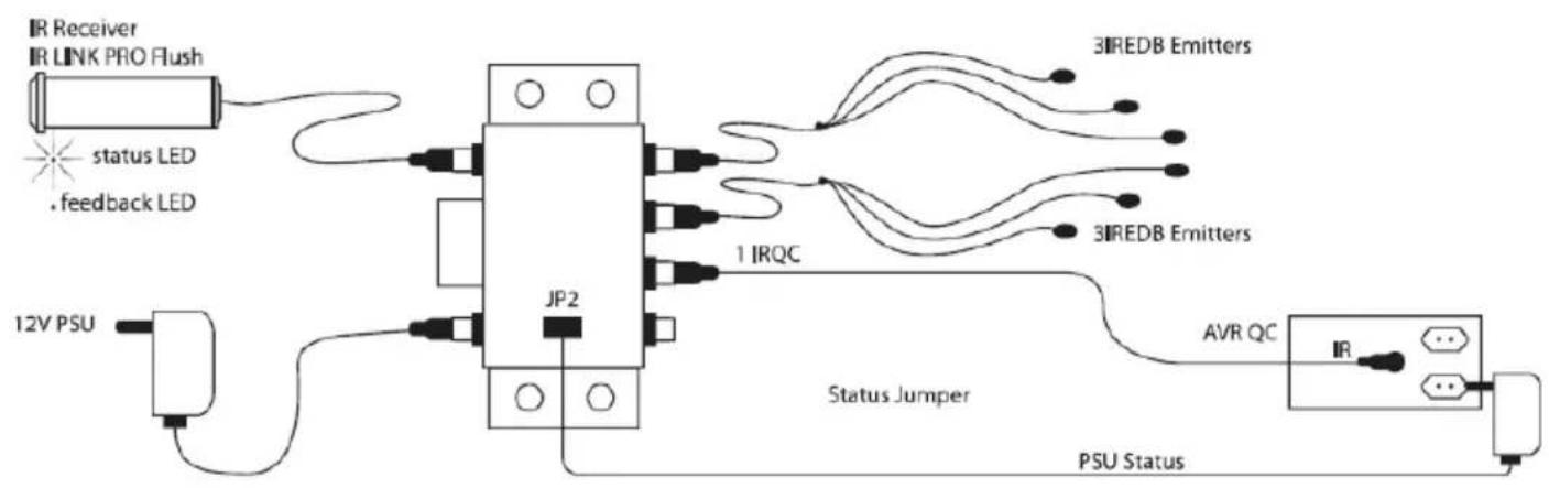
A typical system is shown in Fig. 1 below. Refer to this diagram and the procedure that follows when making connections:

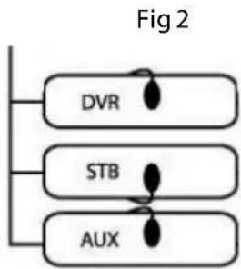
- Attach the 3IREDB Emitters onto the IR Sensor Windows of the components in your system that you wish to control. Refer to Fig. 2.
2a. Plug the yellow mini plugs of the 3IREDB into one of the yellow labelled "EMITTERS" jacks of the IRHUB4 Connecting Hub.
2b. Plug the IRQC cable into one of the yellow labelled "EMITTERS" jacks of the IRHUB4, and the other side into the 3.5 mm mono IR input of your AVR. IRED Mono TS 3.5mm pin configuration: tip is IR Data, sleeve is Ground. (PLEASE CHECK THE MANUAL OF THE DEVICE FOR MATCHING PIN CONFIGURATION)
flowchart
graph TD
    A["DVR"] --> B["STB"]
    B --> C["AUX"]
    style A fill:#f9f,stroke:#333
    style B fill:#ccf,stroke:#333
    style C fill:#cfc,stroke:#333
-
Drill a hole 12 mm wide where you wish to position the IR Receiver. Remove the screw-nut, push the receiver cable and thread through the hole with the lens facing into the room (and in line-of-sight of your handheld remote). Screw the nut back on until tight to hold the IR Receiver in place.
-
Plug the red mini-plug of the IRLPRO Flush IR Receiver into the red labelled "IR RCVR" jack on the IRHUB4 Connecting Hub.
-
Plug the 12VDC Power Supply into an unswitched 230V\~50Hz outlet.
NOTE: It is important that you use an unswitched AC outlet so that the IR system is always active for system power ON commands.
- Plug the 2.1mm "C" plug of the Power Supply Adapter into the "+12VDC" jack on the IRHUB4 Connecting Hub.
STATUS
You can send a Power Status signal to the IRLPRO Flush IR Receiver by connecting a power adapter to this connection (not supplied; 5 - 24VDC & 5 - 12VAC), which e.g. is switched by the device to be controlled. When the A/V device or contact is switched on, the Amber Status LED will light up in the IRLPRO Flush IR Receiver so that you can see that the A/V device is switched on. (see figure 3). The input voltage range is 5 - 24 VDC & 5 - 12 VAC. Socket 2.1mm, pin configuration: centre/red is ST/+VDC, sleeve/black is GND.
flowchart
graph TD
    A["IR Receiver"] --> B["JP2"]
    C["IR LINK PRO Flush"] --> B
    D["status LED"] --> B
    E[".feedback LED"] --> B
    F["12V PSU"] --> G["JP2"]
    H["3IREDB Emitters"] --> I["JP2"]
    I --> J["1 IRQC"]
    K["3IREDB Emitters"] --> L["JP2"]
    L --> M["1 IRQC"]
    N["AVR QC"] --> O["PSU Status"]
    P["IR"] --> Q["PSU Status"]
    R["Status Jumper"] --> S["JP2"]
    T["PSU Status"] --> U["JP2"]
Fig 3
On the top of the cabinet there is a cut out for jumper placement. The default position of the jumper is the parking position JP1. You have 3 different status led response positions:
- Default, JP on position JP1: Feedback LED active & Status LED not-active/unused
- JP on position JP2: Feedback LED & Status LED both always OFF
- JP cable on position JP2 with voltage supply within range: Feedback LED & Status LED active (depending on external voltage being present)
- JP on position JP3: Feedback LED active & Status LED always ON (based on power to IRHUB4)
6. Operation
The IR repeater system should now operate each of the controlled components. When the system is operating correctly, you should see a Blue "talk-back" LED flash on the front of the IRLPRO Flush IR Receiver when you aim your hand held remote control(s) buttons.
7. How to avoid and solve possible problems
Although the ebode IR Link Pro Flush is equipped with proprietary eIR ^2xTM (pronounced Irex) Technology, which guarantees a high level of immunity of InfraRed noise from direct sunlight, CFL lighting and Flat Panel TV's (including Plasma, LCD and LED), in rare cases, the IRLPRO Flush IR Receiver may have to be moved to a different location if the unit is picki interference. This interference may, in severe cases, prevent the system from working.
After repositioning, check to see if the IR Link Pro Flush operates the satellite Receiver or other components. If the IR Link Pro Flush still does not work, reposition the IRED Emitter(s). It may not be located directly over the component's InfraRed receiving "window". Consult the owner's manual of the unit or the manufacturer for the exact location of the InfraRed "window".
IMPORTANT: For installations involving more than two remote rooms, use the services of a competent professional audio/video installer experienced in InfraRed remote control systems.
Do you still have questions? Please refer to www.ebodeelectronics.eu
8. Technical information
IRLPRO FLUSH IR RECEIVER SPECIFICATIONS
-
InfraRed modulation frequency bandwidth: 30 - 60 kHz.
• Cable length 3m, extendable to max. 300 metres (UTP or equivalent).
• Red 3.5mm TRRS plug pin configuration from tip to sleeve: -
Tip = yellow = IR Data
○ Ring 1 = black = Ground
○ Ring 2 = red = +12VDC
○ Sleeve = white = Status
• Reception range: Up to 10 meters, depending on local conditions and remote control used.
- Reception angle: 45 degrees off axis.
• Talkback LED (BLUE). Indicates InfraRed reception only when Emitter(s) are connected.
- Status LED (AMBER). Indicates power status of A/V system
- Maximum number of directly driven IRED IR Emitters: 4 triple Emitters using the IRHUB4 Connecting Hub. Up to six IRLPRO Flush IR Receivers may be connected in parallel screw terminals input of IR Link IRHUB series connecting blocks (e.g. optional IRHUB2CI and IRHUB4). Power requirements: 12 volts DC @ 25 mA. Requires 12VDC Power Supply (included).
- Dimensions IRLPRO Flush IR Receiver: 50 mm x ∅ 16 mm
NOTE: Unit will not work with certain brands & models that operate at higher frequencies (e.g. B&O). Contact ebode Technical Support for more information.
Cable requirements for long lengths to remote rooms:
3-conductor, 24AWG/0,2mm2 solid or stranded wire up to 50m, 22AWG/0,35mm2 up to 100m, 20AWG/0,5mm2 up to 200m and 18AWG/1mm2 up to 300m (unshielded OK).
Maximum transmission length: 300m with category cable (UTP, use white striped together for GND, and use 2 solid colours for IR and 2 solid colours for 12VDC). In case of STATUS wiring, use 1 solid wire for IR and 1 solid wire for Status.
In case of long run un-shielded cable (> 25m), it may be necessary to connect a 470 Ohm 1/8Watt resistor in parallel between IR and GND at the IRHUB connecting block.
IRHUB4 Connecting Hub
- 1x Power: 230V\~50Hz, 12VDC 200mA (supplied)
• 1x 4-Way Wago screw terminal for IR, GND, 12VDC and Status
• 1x Power Status JP2 input: 5 – 12VDC @ 10mA minimum or 5 – 12VAC at 47-63HZ
• 1x JP to C-plug 2.1mm cable, centre positive (not supplied)
• 4x IRED jacks: 3.5mm mono TS-plug
• 1x IR Receiver jack: 3.5mm TRRS-plug - Dimensions: 60x55x20mm

Bedienungsanleitung
INHALT
flowchart
graph TD
    A["DVR"] --> B["STB"]
    B --> C["AUX"]
flowchart
graph TD
    A["DVR"] --> B["STB"]
    B --> C["AUX"]
    C --> A
DECLARATION OF CONFORMITY
Hereby, ebode electronics, declares that this ebode IR Link Pro Flush is in compliance with the essential requirements and other relevant provisions of the following Directives:
Directive 2004/108/EC of the European Parliament and of the Council of 15 December 2004 on the approximation of the laws of the Member States relating to electromagnetic compatibility
Directive 2006/95/EC of the European Parliament and of the Council of 12 December 2006 on the harmonization of the laws of Member States relating to electrical equipment designed for use within certain voltage limits
Directive 2002/95/EC of the European Parliament and of the Council of 27 January 2003 on the restriction of the use of certain hazardous substances in electrical and electronic equipment
Directive 2005/32/EC of the European Parliament and of the Council of 6 July 2005 establishing a framework for the setting of eco design requirements for energy-using
Technical data and copies of the original Declaration of Conformity are available and can be obtained from ebode electronics: PB 25, NL-4264ZG, the Netherlands.
CE
User Information for Consumer Products Covered by EU Directive 2002/96/EC on Waste Electric and Electronic Equipment (WEEE)
This document contains important information for users with regards to the proper disposal and recycling of ebode products. Consumers are required to comply with this notice for all electronic products bearing the following symbol:

Environmental Information for Customers in the European Union
European Directive 2002/96/EC requires that the equipment bearing this symbol on the product and/or its packaging must not be disposed of with unsorted municipal waste. The symbol indicates that this product should be disposed of separately from regular household waste streams.
It is your responsibility to dispose of this and other electric and electronic equipment via designated collection facilities appointed by the government or local authorities. Correct disposal and recycling will help prevent potential negative consequences to the environment and human health.
For more detailed information about the disposal of your old equipment, please contact your local authorities, waste disposal service, or the shop where you purchased the product.
ebode
www.ebodeelectronics.eu

- CONTENTS
- Conformity of Use
- SAFETY WARNINGS
- Introduction
- Kit content
- How does the ebode IR Link Pro Flush work?
- Installing the ebode IR Link Pro Flush
- STATUS
- Operation
- How to avoid and solve possible problems
- Technical information
- IRHUB4 Connecting Hub
- Bedienungsanleitung
- INHALT
- DECLARATION OF CONFORMITY
- CE
- Environmental Information for Customers in the European Union
- ebode
Brand : EBODE
Model : IR Link Pro Flush
Category : Remote control