MB 100 LAN - Thermostat Junkers - Free user manual and instructions
Find the device manual for free MB 100 LAN Junkers in PDF.


| Brand | Junkers |
| Model | MB 100 LAN |
| Product type | Programmable room thermostat |
| Power supply | 230 V ~ 50 Hz or batteries (2 x AA) |
| Connectivity | LAN (Ethernet RJ45) |
| Dimensions (W x H x D) | 120 x 80 x 25 mm |
| Weight | 150 g |
| Display | Backlit LCD screen |
| Temperature range | 5 °C to 30 °C |
| Accuracy | ± 0.5 °C |
| Programming | Weekly, up to 4 periods per day |
| Main functions | PID regulation, holiday mode, frost protection, open window detection |
| Protection rating | IP 20 |
| Energy class | IV (contribution to energy efficiency) |
| Maintenance and cleaning | Clean with a soft, dry cloth. Do not use abrasive products. |
| Safety | Child lock, frost protection, emergency stop |
| Spare parts and repairability | Available from Junkers after-sales service. Repairability index: 7.8/10 |
| General information | Wall thermostat with LAN connection for integration into a home automation system. |
Frequently Asked Questions - MB 100 LAN Junkers
User questions about MB 100 LAN Junkers
0 question about this device. Answer the ones you know or ask your own.
Ask a new question about this device
Download the instructions for your Thermostat in PDF format for free! Find your manual MB 100 LAN - Junkers and take your electronic device back in hand. On this page are published all the documents necessary for the use of your device. MB 100 LAN by Junkers.
USER MANUAL MB 100 LAN Junkers
natural_image
Line drawing of a rectangular enclosure with circular top and bottom corners, marked by warning symbols (no text or labels)[de] Installationsanleitung 2
[en] Installation instruction. 5
[fr] Notice d'installation....8
[it] Istruzioni d'installazione ..... 11
[fl] Installatiehandleiding 14
[et] Paigaldusjuhend 17
[lv] Uzstādīšanas instrukcija 20
[lt] Montavimo instrukcija 23
[cs] Návod k instalaci 26
[pl] Instrukcja instalacji 29
Inhaltsverzeichnis
natural_image
Simple line drawing of a sun icon inside a rectangular frame (no text or symbols)1 Key to symbols and safety instructions .... 5
1.1 Explanation of symbols 5
1.2 Safety instructions 5
2 Product details.... 5
2.1 Standard delivery 5
2.2 Cleaning and care 5
2.3 Specification 6
3 Installation 6
3.1 Installation 6
3.2 Electrical connections 6
4 Commissioning....6
5 Environmental protection/Disposal 6
6 Troubleshooting....7
Appendix 32
1 Key to symbols and safety instructions
1.1 Explanation of symbols
Important information

Important information in cases where there is no risk of personal injury or material losses is identified by the symbol shown on the left. It is bordered by horizontal lines above and below the text.
Additional symbols
| Symbol | Meaning |
| ▶ | a step in an action sequence |
| → | a reference to a related part in the document or to other related documents |
| • | a list entry |
| - | a list entry (second level) |
Table 1
1.2 Safety instructions
▶Observe all country-specific regulations and standards during installation and operation.
▶Observe all instructions to ensure satisfactory operation.
- This product must only be installed and commissioned by an approved contractor.
▶Never install this product in wet rooms.
▶Install and commission heat sources and other accessories according to the relevant instructions.
▶Use this product exclusively in conjunction with the programming units and heat sources listed. Observe connection diagram.
▶ Use the power supply unit provided to connect this product to the 230 V mains supply.
About these instructions
These installation instructions contain important information regarding the safe and proper installation, commissioning and maintenance of the product.
These installation instructions are intended for qualified contractors who, as a result of their training and experience, are skilled in dealing with electrical installations and heating systems.
2 Product details

You will need an internet connection to make use of all functions. This may incur additional costs. In addition, control of the system with a smartphone will require a chargeable App, JunkersHome.
- Interface between heating system and a network (LAN) ^1)
•Control and monitoring of a system with an smartphone 2)

The MB LAN cannot be combined with a room temperature-dependent FR 50.
•May be combined with the following:
- Heat sources with 2-wire BUS interface and controllers FW.../FR... from FD 889 (09/2008) with 2-wire BUS interface, e.g. FW 200
- Modules for controllers FW.../FR... from FD 889 (09/2008), e.g. ISM2.
2.1 Standard delivery
Fig. 1, page 32:
[1] Module
[2] Plug power supply with connecting cable (2 m long)
[3] LAN cable CAT 5 (2 m long)
[4] Bag with fitting parts (screws, rawl plugs, connectors for 2-wire BUS interface)
[5] Installation instructions
2.2 Cleaning and care
▶ If required, wipe the enclosure with a damp cloth. Never use chemically aggressive or acidic cleaning agents.
2.3 Specification
| Specification | |
| Dimensions (W × H × D) | 151 × 184 × 61 mm (further dimensions → Fig. 2, page 32) |
| Maximum cross-section (terminals) | 2.5 mm^2 |
| Rated voltages: | |
| •BUS | •12 V to 15 V DC (reverse polarity protected) |
| •Module power supply | •Plug power supply unit supplied 230 V AC/7.5 V DC, 700 mA |
| Interfaces | •2-wire BUS•LAN: 10/100 MBit/s (RJ45) |
| Power consumption | 1.5 VA |
| Permissible ambient temperature | 0 ... 50 °C |
| IP rating | IP20 |
Table 2
3 l n s t a l l a t
3.1 Installation
▶ Removing the cover ( Fig. 3, page 32)
▶ Fitting the module ( Fig. 4, page 32)
▶ Fixing the module ( Fig. 5, page 32)
3.2 Electrical connections
Connections and interfaces
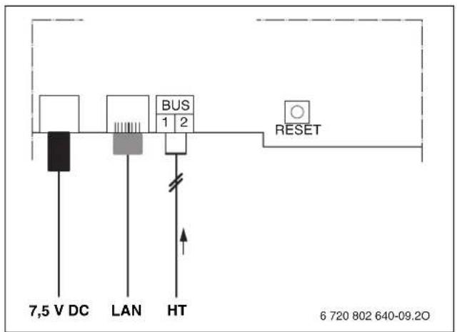
Legend to Fig. 6, page 33:
7,5 V DC Power supply unit connection
HT 2-wire BUS system connection
LAN LAN connection (RJ45)
RESET RESET button
Pre-assembling the grommets and connecting the cables
▶ Open out the grommets to match the cable diameter and make an incision on one side ( Fig. 7, page 33).
▶ Fit the grommets and connect the cables ( Fig. 8, page 33).
BUS connection
▶ Connect BUS subscribers with two BUS connectors in series ( Fig. 6, page 33) or BUS subscriber [B] with one junction box [A] in a star configuration ( Fig. 9, page 33).

If the maximum cable length of the BUS connection between all BUS subscribers is exceeded, the system cannot be commissioned.
| Cable length | Conductor cross-section |
| ≤ 80 m | 0.40 mm ^2 |
| ≤ 100 m | 0.50 mm ^2 |
| ≤ 150 m | 0.75 mm ^2 |
| ≤ 200 m | 1.00 mm ^2 |
| ≤ 300 m | 1.50 mm ^2 |
Table 3 Total BUS length
▶ All LV leads must be routed separately from cables carrying mains voltage to avoid inductive interference (minimum separation 100 mm).
▶In case of external inductive interference, shield the cables.
This ensures that the cables are shielded from external interference (e.g. heavy current cables, overhead wires, transformer stations, radio and television set, amateur radio stations, microwave ovens etc).
▶ Fit the cover and plug in the power supply unit supplied.
4 Commissioning

During commissioning, the LED on the module illuminates in red if neither the BUS nor the LAN connection is made.
The router must be configured as follows:
•DHCP enabled
•Ports 5222 and 5223 not blocked
• Free IP address available
- Address filtering (MAC filter) matched to the module.
The module automatically obtains an IP address from the router. The name and address of the target server are stored in the standard settings of the module. If there is an internet connection, the module automatically logs into the Junkers-Server.
The router does not necessarily have to be connected to the internet. The module can also be operated using the local network only. If this is the case, access to the heating system via the internet or automatic updates of the module software are not possible.
The first time the JunkersHome App starts, you will be prompted to enter the factory-set login name and password. These login details are printed on the module data plate.
Data plate
Legend to Fig. 10, page 33:
[1] Data plate with login details, MAC address and serial number
[2] DIP switch (no function)
Testing the connection (with heating circuit 1 logged on)
You can check whether the module is communicating correctly with the heating system.
▶ Press the RESET button ( Fig. 6, page 33) briefly in order to change the operating mode for heating circuit 1 at the controller.
The controller display shows the modified operating mode (heating or economy)
▶ To conclude the connection test, reinstate the required operating mode.
Resetting personal settings
If you have forgotten your personalised login name or password:
▶ Hold down the RESET button ( Fig. 6, page 33) for at least 5 seconds.
If you have forgotten your personalised login name or password: ▶ Hold down the RESET button ( Fig. 6, page 33) for at least 5 seconds.
The factory-set login details are restored.
5 Environmental protection/Disposal
Environmental protection is a key commitment of the Bosch Group.
Quality of products, efficiency and environmental protection are equally important objectives for us. Laws and regulations aimed at protecting the environment are strictly adhered to.
To protect the environment we will, subject to economical aspects, use the best possible technology and materials.
Packaging
We participate in the recycling programmes of the countries in which our products are sold to ensure optimum recycling.
All of our packaging materials are environmentally compatible and can be recycled.
Used appliances
Used appliances contain valuable materials that should be recycled. The various assemblies can be easily dismantled and synthetic materials are marked accordingly. Assemblies can therefore be sorted by composition and passed on for recycling or disposal.
6 Troubleshooting

For information on troubleshooting the router or smartphone, see the relevant manufacturer's instructions.
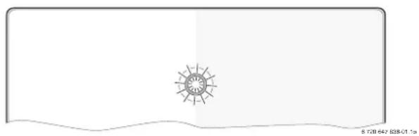
The indicator shows the operating condition of the module.
natural_image
Simple line drawing of a sun with rays, no text or symbols presentON/OFF
| indicator | Possible cause Remedy | |
| Constantly OFF | Power supply interrupted. | ►Switch ON power supply. |
| Power supply unit cable not connected to module. | ►Make connection. | |
| Power supply unit faulty. | ►Replace power supply unit. | |
| Constantly red | When commissioning or restoring factory settings: Neither BUS nor LAN connection available. | ►Disconnect module from power supply.►Make BUS and LAN connections.►Recommission module. |
| Otherwise: internal fault | ►Replace module. | |
| Flashing red | LAN cable not connected. | ►Make LAN connection. |
| Router is switched off. | ►Switch router on 1). | |
| DHCP is disabled. ►Enable DHCP at router 1). | ||
| Manually set MAC filter prevents IP address being issued. | ►Set MAC filter for the MAC address printed on the enclosure (→ Fig. 10, [1], page 33). | |
| No IP address available for the module. | ►Check router configuration 1). | |
| LAN cable faulty. | ►Replace LAN cable. | |
| Alternating red and green | BUS and LAN connection separated after commissioning. | ►Disconnect module from power supply.►Make BUS and LAN connections.►Recommission module. |
Table 4 Fault table
| ON/OFF indicator | Possible cause Remedy | |
| Constantly orange | LAN connection established; no access to Junkers server via internet. | ▶Disconnect module from power supply for 10 seconds and recommission it.-or-▶Establish internet connection ^1) .-or-▶If internet access for the router is periodically blocked, remove the timeout ^1) .-or-▶Open ports 5222 and 5223 ^1) . |
| Flashing green | Heat source switched off. | ▶Switch ON heat source. |
| Module not connected to BUS system. | ▶Make BUS connection. | |
| Maximum cable length for BUS connection exceeded. | ▶Make shorter BUS connection. | |
| Short circuit or cable break in the BUS connection. | ▶Check BUS connection and repair if required. | |
| Constantly green | No faults. Standard operation. | |
Table 4 Fault table
1) See manufacturer's instructions.

Faults with effects on the App function are also shown on the App (e.g. no connection with the XMPP server, no connection with the MB LAN, incorrect password, ...).
Table des matières
natural_image
Simple line drawing of a sun icon on a white background with no text or symbolsnatural_image
Simple line drawing of a sun icon inside a rectangular frame (no text or symbols)natural_image
Simple line drawing of a sun icon inside a rectangular frame with wavy bottom edge (no text or symbols)natural_image
Simple line drawing of a sun icon inside a rectangular frame with a wavy bottom edge (no text or symbols)natural_image
Simple line drawing of a sun icon on a white background with a wavy base (no text or symbols)natural_image
Simple line drawing of a sun with rays, no text or symbols presentnatural_image
Simple line drawing of a sun with rays, no text or symbols presentnatural_image
Simple line drawing of a sun with rays, enclosed in a rectangular frame (no text or symbols)1

3

4

2

5
6

flowchart
graph TD
    A["A"] -->|2| B["B BUS BUS"]
    A -->|2| C["B BUS BUS"]
    A -->|2| D["B BUS BUS"]
    B -->|≥100 mm| E["Ground"]
    C -->|≥100 mm| F["Ground"]
    D --> G["Ground"]
9

7

10

8

JUNKERS
Robert Bosch Sp. z o.o.
ul. Jutrzenki 105
02-231 Warszawa
Infolinia: 0801 600 801
Infolinia serwis: 0801 300 810
www.junkers.pl
- Inhaltsverzeichnis
- Key to symbols and safety instructions .... 5
- Product details.... 5
- Installation 6
- Commissioning....6
- Environmental protection/Disposal 6
- Troubleshooting....7
- Key to symbols and safety instructions
- Explanation of symbols
- Important information
- Safety instructions
- About these instructions
- Product details
- Standard delivery
- Fig. 1, page 32:
- Cleaning and care
- l n s t a l l a t
- Installation
- Electrical connections
- Connections and interfaces
- Legend to Fig. 6, page 33:
- Pre-assembling the grommets and connecting the cables
- BUS connection
- Commissioning
- Data plate
- Legend to Fig. 10, page 33:
- Testing the connection (with heating circuit 1 logged on)
- Resetting personal settings
- Environmental protection/Disposal
- Packaging
- Used appliances
- Troubleshooting
- Table des matières
- JUNKERS
Brand : Junkers
Model : MB 100 LAN
Category : Thermostat