FR 110 - Thermostat Junkers - Free user manual and instructions
Find the device manual for free FR 110 Junkers in PDF.


| Product Type | Room Thermostat |
| Model | FR 110 |
| Brand | Junkers |
| Control Type | Digital with LCD Display |
| Temperature Range | 5°C to 35°C |
| Accuracy | ±0.5°C |
| Power Supply | 2x AA Batteries |
| Dimensions (W x H x D) | 80 x 80 x 30 mm |
| Weight | 200 g |
| Display | Backlit LCD |
| Programmable | Yes, 7-Day Programmable |
| Number of Programs | Up to 6 Daily Schedules |
| Frost Protection | Yes |
| Sensor Type | Built-in NTC Thermistor |
| Mounting | Wall-Mounted (Screw or Adhesive) |
| Connection | 2-Wire Connection for Heating System |
| Maintenance | Clean with Dry Cloth |
| Battery Life | Approximately 1 Year |
| Safety Features | Low Battery Warning, Overheat Protection |
| Spare Parts Availability | Contact Authorized Service Center |
Frequently Asked Questions - FR 110 Junkers
User questions about FR 110 Junkers
0 question about this device. Answer the ones you know or ask your own.
Ask a new question about this device
Download the instructions for your Thermostat in PDF format for free! Find your manual FR 110 - Junkers and take your electronic device back in hand. On this page are published all the documents necessary for the use of your device. FR 110 by Junkers.
USER MANUAL FR 110 Junkers
Room temperature controller with solar control
FR 100 / FR 110

BOSCH
Installation and operating instructions
Overview of controls and symbols

Fig. 1 Controls
Controls
1 Turn rotary selector in + direction: scroll menu/information up or increase setting
Turn rotary selector in - direction: scroll menu/information down or decrease setting
Press rotary selector open menu or confirm setting/value or switch heating circuit
2 Operating mode selector for heating circuits:
| auto | Automatic mode |
| Constant Comfort | |
| Constant Economy | |
| Constant Frost |
3: Bring forward the next switching point and the associated operating mode = Comfort, Economy, Frost for the heating circuit to the current time.
4 Activate DHW heating immediately. The DHW cylinder is heated to the required temperature for 60 minutes or, with combi boilers, comfort mode is activated for 30 minutes.
5 : Open/close menu
6: Show settings
7 : Delete/reset setting
8 : Return to next menu up
Tab. 1
Symbols
23.5°
Current room temperature
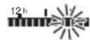
Flashing segment: Current time (13:45 to 14:00)

Solid segments: time set for operating mode ✦ Comfort today or DHW On (or ≥ 50 °C) (1 segment = 15 min)
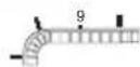
Empty segments: time set for operating mode Ⓗ Economy today or DHW Off (or > 20 °C and < 50 °C) (1 segment = 15 min)

No segments: time set for operating mode ❖ Frost today or DHW ≤ 20 °C (1 segment = 15 min)

Operating mode Comfort for heating circuit

Operating mode Economy for heating circuit

Operating mode Frost for heating circuit

Automatic mode for heating circuit Holiday mode

Burner operation

Return to next menu up

Other display information (menu points) are available. They can be viewed by turning the rotary selector
Tab. 2
Contents

Chapters against a grey background are intended for installers. The pages concerned are identified by a grey vertical bar at the side of the page.
1 Key to symbols and safety instructions . 7
1.1 Key to symbols 7
1.2 Safety instructions 8
2 Technical data for the accessory item ... 9
2.1 Standard delivery ..... 10
2.2 Specification 10
2.3 Supplementary accessories ..... 11
2.4 Cleaning 11
2.5 Sample system 12
3 Installation (for contractors only) ..... 14
3.1 Installation 14
3.1.1 Fitting the heating controller ..... 14
3.1.2 Fitting other accessories ..... 15
3.1.3 Disposal 15
3.2 Electrical connections ..... 16
3.2.1 Connecting the BUS link ..... 16
3.2.2 Connect the analogue 1-2-4 interface (only FR 100) .....17
4 Commissioning (contractors only) .... 18
5 Operation 20
5.1 Heating and DHW programs ..... 21
5.1.1 General 21
5.1.2 Weekly programs ..... 21
5.1.3 Structure of programs ..... 21
5.2 Setting programs ..... 22
5.2.1 Display views and menu navigation 22
5.2.2 Setting and changing switching times and operating modes .....23
5.3 Manually setting operating modes 27
5.3.1 Selecting the operating mode for heating .....27
5.3.2 Advancing heating mode before the programmed time (bringing forward the next switching point) 27
5.3.3 Changing DHW mode
(time-limited) 28
5.3.4 Holiday program ..... 28
5.4 Changing the set room temperature 29
5.4.1 Permanently changing the set room temperature 29
5.4.2 Changing the set room temperature for a limited period ..... 29
6 Adjusting the MAIN MENU ..... 30
6.1 Overview and adjustment of the MAIN MENU 30
6.1.1 MAIN MENU: Holiday ..... 31
6.1.2 MAIN MENU: Heating ..... 32
6.1.3 MAIN MENU: Domestic hot water . 34
6.1.4 MAIN MENU: General settings . . . 36
6.1.5 MAIN MENU: Solar ..... 36
6.2 Heating program ..... 37
6.2.1 Time programs for heating ..... 37
6.2.2 Temperature levels for the operating modes 40
6.3 DHW program ..... 40
6.3.1 Time program for DHW with
combi boiler 42
6.3.2 Time program for DHW with DHW cylinder and combi boiler (FR 100) 43
6.3.3 Time/temperature level program for DHW (only with FR 110 and DHW cylinder) 44
6.3.4 Time program for DHW circulation pump (only with FR 110 and DHW cylinder)....46
6.3.5 DHW parameters (only with FR 110 and DHW cylinder) ..... 47
6.3.6 Thermal disinfection of hot water (with DHW cylinder only) ..... 48
6.4 General settings ..... 49
6.4.1 Time and Date ..... 49
6.4.2 Display formats ..... 49
6.4.3 Key lock 49
6.4.4 Language ..... 49
6.5 Solar settings ..... 50
7 Viewing information .... 51
8 Menu settings INSTALLER SETTINGS (for contractors only) ..... 54
8.1 Summary and settings of the INSTALLER SETTINGS menu ..... 54
8.1.1 INSTALLER SETTINGS: System configuration ..... 55
8.1.2 INSTALLER SETTINGS: Heating parameters ..... 55
8.1.3 INSTALLER SETTINGS: Solar system config ..... 55
8.1.4 INSTALLER SETTINGS: Solar sys parameters ..... 56
8.1.5 INSTALLER SETTINGS: Fault history ..... 56
8.1.6 INSTALLER SETTINGS: Cust service address ..... 56
8.1.7 INSTALLER SETTINGS: System info .... 57
8.2 Configuring the heating system ... 58
8.3 Parameters for heating ..... 59
8.4 Configuring the solar thermal system 60
8.5 Parameters for solar thermal system 60
8.5.1 Commissioning the solar thermal system 61
8.5.2 Parameters for the standard solar thermal system .....61
8.5.3 Parameters for solar optimisation . 62
8.6 Fault history ..... 64
8.7 Viewing and entering the customer service address 64
8.8 Viewing system information ..... 64
9 Troubleshooting 65
9.1 Troubleshooting using the display (for heating contractors only) .... 65
9.2 Troubleshooting without using display .... 71
10 Energy saving tips .... 73
11 Environmental protection ..... 75
12 Commissioning report for the heating system 76
13 Individual time program settings ..... 77
13.1 Heating program for the assigned heating circuit 77
13.2 DHW program 83
13.3 DHW circulation program (only with FR 110 and DHW cylinder) .. 84
Index 85
Information about this documentation
Guide to instructions

These installation and operating instructions contain all details of the function and operation of the FR 100 and FR 110 heating controllers.
If you ...
• ... are looking for the safety instructions and an explanation of the symbols, refer to chapter 1.
- ... are looking for a summary of the design and function of the FR 100 heating controller, refer to chapter 2. You will also find the specification there.
• ... are a HEATING ENGINEER and want to know how to install, electrically connect and commission this accessory, refer to chapters 3 and 4.
- ... want to know how to operate and program this accessory, refer to chapters 5, 6 and 13. There you will also find summaries of the factory settings and setting ranges for the menus. There are also tables for making a note of your settings.
- ... want to view information about the operating condition of the heating system, refer to chapter 7.
- ... are a HEATING CONTRACTOR and want to make expert settings or view system information, refer to chapter 8. There you will also find summaries of the factory settings and setting ranges for the menus. There are also tables for making a note of your settings.
• ... are looking for troubleshooting tables, refer to chapter 9.
• ... are looking for tips on saving energy, refer to chapter 10.
- ... are looking for a particular keyword in the document, have a look in the Keyword index on the last pages.
Additional documentation for the heating contractor (not included in standard pack)
In addition to these instructions supplied with the product, the following documents are also obtainable:
- Spare parts catalogue
- Servicing instructions (for troubleshooting and checking functions)
These documents can be requested from the Bosch Information Service. The contact address is printed on the back page of these instructions.
1 Key to symbols and safety instructions
1.1 Key to symbols
Warnings

Warnings in this document are framed and identified by a warning triangle printed against a grey background.

If there is a danger due to electricity, the exclamation mark in the warning triangle is replaced by a lightning symbol.
Keywords at the start of a warning indicate the type and seriousness of the ensuing risk if measures to prevent the risk are not taken.
- NOTE indicates that material losses may occur.
- CAUTION indicates that minor to medium injury may occur.
- WARNING indicates that severe injury may occur.
• DANGER indicates a risk to life.
Important information

Important information where there is no risk to people or property is indicated with the adjacent symbol. It is bordered by lines above and below the text.
Additional symbols
Symbol Explanation
▶ Action step
→ Cross-reference to other parts of this document or to other documents
- List/list entry
- List/list entry (second level)
Tab. 3
Conventions used in these for representing the menu structure:
- Individual menu levels are separated by the > symbol, e.g. Holiday > Start
- Parameters that can be set/selected on a menu are marked with a bullet point • .
- The operation of control elements is indicated by the symbol for the control:
- means turn rotary selector
- means press rotary selector
- means press and release menu key
- means press and release info key
- means press and release delete/reset key
- means press and release menu up key
- means press and release advance switching time key
- means press and release immediate DHW key
1.2 Safety instructions
▶ These instructions must be observed to ensure correct operation.
▶ Install and commission the heating appliance and all accessories in accordance with the instructions provided.
This accessory must only be installed by suitably qualified installers.
▶ Only use these accessories in conjunction with the heating appliances listed. Follow the connection diagram!
▶ Never connect this accessory to the 220 to 240 V mains.
▶ Prior to the installation of this accessory: Isolate the heating appliance and all other BUS subscribers from the power supply (220 to 240 V AC).
▶ For wall mounting: never install this accessory in wet areas.
▶ Instruct customers about the functions and operation of the accessory.
▶ Risk of scalding during thermal disinfection: Supervise short periods of operation with water temperatures over 60 °C or fit a thermostatic DHW mixer.
▶ When there is a risk of frost, leave the heating appliance switched on and follow the frost protection information.
Risk of damage due to operator error.
Incorrect operation can cause injury and/or material damage.
▶ Ensure children do not operate this accessory unsupervised or play with it.
▶ Make sure that only people who are capable of operating this accessory properly have access to it.
2 Technical data for the accessory item
| Controller | FR 110 | FR 100 | FR 100 with Bosch Heatronic (analogue 1-2-4 interface) | |
| Heating appliance | with BUS-enabled Heatronic 3 | with BUS-enabled Heatronic 3 | ||
| Wall mounting X X | X | |||
| 1 non-mixed heating circuit X X | X | |||
| HK 2 ... HK 10 via FR 10/FR100 X | 1) | X^1) | ||
| Time/temperature level profile for associated heating circuit | XX | X | ||
| Heat-up optimisation X X | X | |||
| DHW heating X X | ||||
| DHW heating via heating appliance with DHW heating acc. to instantaneous water heater principle | XX | X | 2) | |
| DHW heating via DHW cylinder on heating appliance | XX | X | 2) | |
| DHW heating via DHW cylinder downstream of low loss header | X | |||
| Thermal disinfection X X | ||||
| Time program for DHW heating | XX | |||
| Time program for DHW circulation pump | X | |||
| Time/temperature level profile for DHW | X | |||
| Solar thermal system | X^3) | X^3) | ||
| Thermal disinfection of solar cylinder | X^3) | X^3) | ||
Tab. 4 Operating characteristics of these controllers
1) with IPM ...
2) controlled by the heating appliance
3) with ISM ...
- The controller has a power reserve sufficient for at least 6 hours of operation. If the controller is without power for a period longer than the power reserve then the time and date will be deleted. All other settings are saved.
2.1 Standard delivery
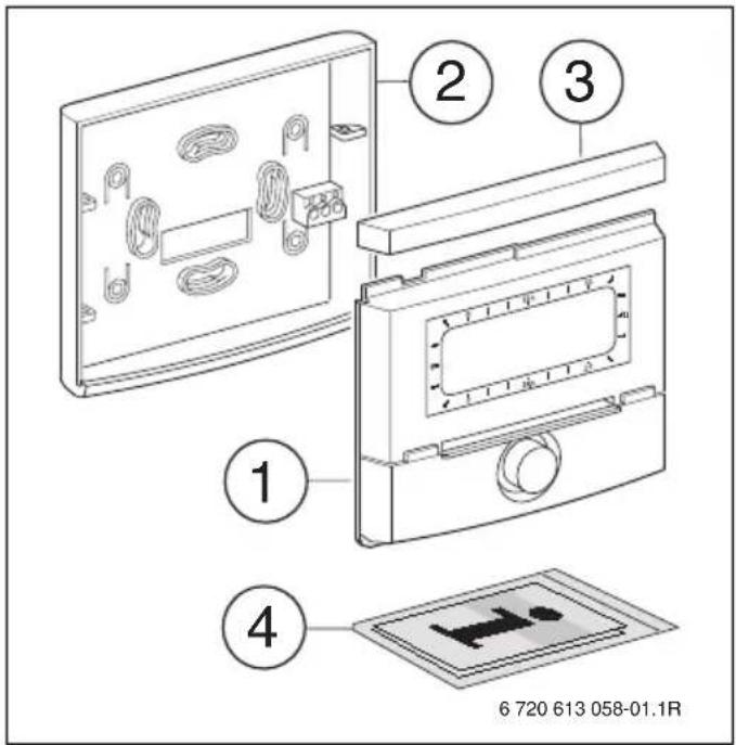
Fig. 2 Standard delivery
1 Controller top section
2 Base for wall mounting
3 Slide cover
4 Installation and operating instructions
2.2 Specification
| Dimensions Fig. 5, page 14 | |
| Rated voltage 10...24 V DC | |
| Rated current (excluding illumination) | 6 mA |
| Controller output: - FR 100 / FR 110 - FR 100 (alternative) | 2-wire BUS 1-2-4 interface |
| Permiss. ambient temp. | 0 ... +50 °C |
| IP rating III | |
| Protection class IP20 | |
Tab. 5 Specification
2.3 Supplementary accessories
See also the pricelist.
- IPM 1: Module for controlling one mixed or one non-mixed heating circuit.
- IPM 2: Module for controlling up to two mixed heating circuits. Controlling one non-mixed heating circuit in the heating system is possible.
- ISM 1: Module for controlling solar DHW heating.
- FR 10: Room temperature controller without heating program to extend the heating system by one additional heating circuit (not permissible in Germany).
2.4 Cleaning
▶ If required, use a damp cloth to wipe the controller casing. Never use aggressive or acidic cleaning agents for this.
2.5 Sample system
flowchart
graph TD
    A["WW"] --> B["S...solar"]
    B --> C["TWM"]
    C --> D["HP"]
    D --> E["ZW..."]
    E --> F["FWK"]
    F --> G["IPM 2"]
    G --> H["IPM 2"]
    H --> I["IPM 2"]
    I --> J["IPM 2"]
    J --> K["IPM 2"]
    K --> L["IPM 2"]
    L --> M["IPM 2"]
    M --> N["IPM 2"]
    N --> O["IPM 2"]
    O --> P["IPM 2"]
    P --> Q["IPM 2"]
    Q --> R["IPM 2"]
    R --> S["IPM 2"]
    S --> T["IPM 2"]
    T --> U["IPM 2"]
    U --> V["IPM 2"]
    V --> W["IPM 2"]
    W --> X["IPM 2"]
    X --> Y["IPM 2"]
    Y --> Z["IPM 2"]
    Z --> AA["IPM 2"]
    AA --> AB["IPM 2"]
    AB --> AC["IPM 2"]
    AC --> AD["IPM 2"]
    AD --> AE["IPM 2"]
    AE --> AF["IPM 2"]
    AF --> AG["IPM 2"]
    AG --> AH["IPM 2"]
    AH --> AI["IPM 2"]
    AI --> AJ["IPM 2"]
    AJ --> AK["IPM 2"]
    AK --> AL["IPM 2"]
    AL --> AM["IPM 2"]
    AM --> AN["IPM 2"]
    AN --> AO["IPM 2"]
    AO --> AP["IPM 2"]
    AP --> AQ["IPM 2"]
    AQ --> AR["IPM 2"]
    AR --> AS["IPM 2"]
    AS --> AT["IPM 2"]
    AT --> AU["IPM 2"]
    AU --> AV["IPM 2"]
    AV --> AW["IPM 2"]
    AW --> AX["IPM 2"]
    AX --> AY["IPM 2"]
    AY --> AZ["IPM 2"]
    AZ --> BA["IPM 2"]
    BA --> BB["IPM 2"]
    BB --> BC["IPM 2"]
    BC --> BD["IPM 2"]
    BD --> BE["IPM 2"]
    BE --> BF["IPM 2"]
    BF --> BG["IPM 2"]
    BG --> BH["IPM 2"]
    BH --> BI["IPM 2"]
    BI --> BJ["IPM 2"]
    BJ --> BK["IPM 2"]
    BK --> BL["IPM 2"]
    BL --> BM["IPM 2"]
    BM --> BN["IPM 2"]
    BN --> BO["IPM 2"]
    BO --> BP["IPM 2"]
    BP --> BQ["IPM 2"]
    BQ --> BR["IPM 2"]
    BR --> BS["IPM 2"]
    BS --> BT["IPM 2"]
    BT --> BU["IPM 2"]
    BU --> BV["IPM 2"]
    BV --> BW["IPM 2"]
    BW --> BX["IPM 2"]
    BX --> BY["IPM 2"]
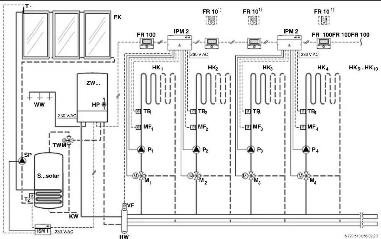
Fig. 3 FR 100 and combi boiler: Simplified system scheme (see technical guides for installation illustration and further options)

flowchart
graph TD
    A["WW"] --> B["WWKG TWM"]
    B --> C["ZP"]
    C --> D["S...solar"]
    D --> E["SP"]
    E --> F["ISM 1 230 V/AC"]
    F --> G["KW"]
    G --> H["WP"]
    H --> I["HP"]
    I --> J["ZF"]
    J --> K["SW"]
    K --> L["230 V/AC"]
    L --> M["ZS..."]
    M --> N["IPM 2"]
    N --> O["FR 10¹"]
    N --> P["FR 10¹"]
    N --> Q["FR 10¹"]
    N --> R["FR 10¹"]
    N --> S["IPM 2"]
    S --> T["FR 100"]
    T --> U["FR 100"]
    T --> V["FR 100"]
    T --> W["IPM 2"]
    W --> X["FR 10¹"]
    W --> Y["FR 10¹"]
    W --> Z["FR 10¹"]
    W --> AA["IPM 2"]
    AA --> AB["FR 100"]
    AB --> AC["230 V AC"]
    AC --> AD["HK₁"]
    AC --> AE["HK₂"]
    AC --> AF["HK₃"]
    AC --> AG["HK₄"]
    AC --> AH["HK₅...HK₁₀"]
    AC --> AI["M₁, M₂, M₃, M₄, PF"] --> AJ["TB₁, TB₂, TB₃, TB₄, MF₁, MF₂, MF₃, MF₄, P₁, P₂, P₃, P₄"] --> AK["TB₁, TB₂, TB₃, TB₄, MF₁, MF₂, MF₃, MF₄, P₁, P₂, P₃, P₄"] --> AL["TB₁, TB₂, TB₃, TB₄, MF₁, MF₂, MF₃, MF₄"] --> AM["TB₁, TB₂, TB₃, TB₄, MF₁, MF₂, MF₃, P₁, P₂, P₃"] --> AN["TB₁, TB₂, TB₃, TB₄, MF₁, MF₂, MF₃"] --> AO["TB₁, TB₂, TB₃, TB₄, MF₁, MF₂, MF₃"] --> AP["TB₁, TB₂, TB₃, TB₄, MF₁"] --> AQ["TB₁, TB₂, TB₃, TB₄, MF₁"] --> AR["TB₁, TB₂, TB₃, TB₄, MF₁"] --> AS["TB₁, TB₂, TB₃, TB₄, MF₁"] --> AT["TB₁, TB₂, TB₃, TB₄, MF₁"] --> AU["TB₁, TB₂, TB₃, TB₄, MF₁"] --> AV["TB₁, TB₂, TB₃, TB₄, MF₁"] --> AW["TB₁, TB₂, TB₃, TB₄, MF₁"] --> AX["TB₁, TB₂, TB₃, TB₄, MF₁"] --> AY["TB₁, TB₂, TB₃, TB₄, MF₁"] --> AZ["TB₁, TB₂, TB₃, TB₄, MF₁"] --> BA["TB₁, TB₂, TB₃, TB₄, MF₁"] --> BB["TB₁, TB₂, TB₃, TB₄, MF₁"] --> BC["TB₁, TB₂, TB₃, TB₄, MF₁"] --> BD["TB₁, TB₂, TB₃, TB₄, MF₁"] --> BE["TB₁, TB₂, TB₃, TB₄"] --> BF["TB₁, TB₂, TB₃"]
Fig. 4 FR 110 and heating appliance with DHW cylinder connection: Simplified system scheme (see technical guides for installation illustration and further options)
Key to Fig. 3 and Fig. 4:
FR 10 Room temperature controller for additional heating circuit
FR 100 Room temperature controller for combi boiler
FR 110 Room temperature controller for heating appliance with DHW cylinder
FK Flat-plate collector
HK1...10 Heating circuits
HP Heating circuit pump
HW Low loss header
IPM 2 Module for two heating circuits
ISM 1 Module for solar DHW heating
KW Cold water connection
M1...10 Mixer motor
MF_110 Flow temperature sensor, mixed heating circuit
P_110 Heating circuit circulation pump
PE Thermal disinfection pump
S...solar Solar cylinder
SF Cylinder temperature sensor (NTC)
SP Solar circuit pump
T_1 Collector temperature sensor
T_2 Cylinder temperature sensor, bottom
TB1...10 Temperature monitor
TWM Thermostatic DHW mixer (to protect combi boiler against overheating)
VF Common flow temperature sensor
WW DHW connection
ZS... Heating appliance with cylinder connection
ZW... Combi boiler
1) Option FR 10 or FR 100
3 Installation (for contractors only)
The detailed system scheme for installing the hydraulic components and the associated control devices can be found in the technical guides or tender specifications.

DANGER: Risk of electric shock!
▶ Prior to the installation of this accessory: Isolate the heating appliance and all other BUS subscribers from the power supply (220 to 240 V AC).
3.1 Installation
3.1.1 Fitting the heating controller
The control quality of the controller is dependent on where it is installed.
The installation location (= lead room) must be suitable for controlling the associated heating circuits.
▶ Select the installation location.
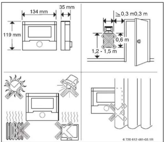
Fig. 5

The mounting surface on the wall should be level.
▶ Remove the top section and slide cover from the base.

Fig. 6
▶ Fit the base.

Fig. 7
▶ Make the electrical connections ( Fig. 11 on page 17 or 9 on page 16).
▶ Refit top section and slide cover on base.
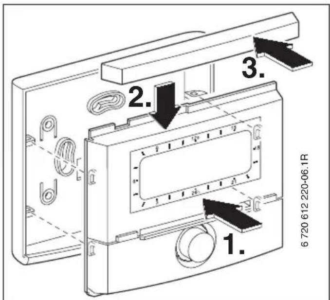
Fig. 8
3.1.2 Fitting other accessories
▶ Fit accessories according to the legal requirements and the installation instructions supplied with them.
3.1.3 Disposal
▶ Dispose of packaging in an environmentally responsible manner.
▶ When replacing components, dispose of the used components in an environmentally responsible manner.
3.2 Electrical connections
▶ Use electrical cable according to local codes and requirements.
▶ Route all LV cables/leads separately from cables carrying 220 to 240 V or 380 to 415 V to avoid inductive interference (minimum separation 100 mm).
▶ In case of external inductive interference, shield the cables.
This ensures that the cables are shielded from external interference (e.g. heavy current cables, overhead wires, transformer stations, radio and television set, amateur radio stations, microwave ovens etc).
3.2.1 Connecting the BUS link
Permissible lead lengths from the BUS-enabled Heatronic 3 to the controller:
| Lead length Cross-section | ||
| ≤ 80 m 0.40 mm | 2 | |
| ≤ 100 m 0.50 mm | 2 | |
| ≤ 150 m 0.75 mm | 2 | |
| ≤ 200 m 1.00 mm | 2 | |
| ≤ 300 m 1.50 mm | 2 | |
Tab. 6
- Connect the controller to a heating appliance with BUS-enabled Heatronic 3.

Fig. 9 Controller connected to BUS-enabled Heatronic 3.

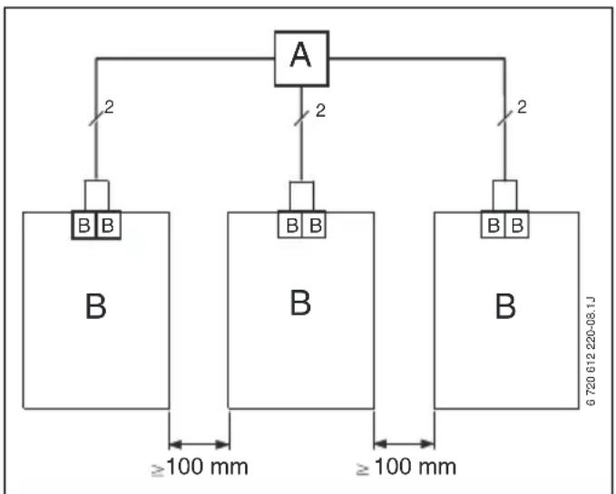
If the BUS links feature different cross-sections:
▶ Connect BUS links via a branch box.
flowchart
graph TD
    A["A"] -->|2| B1["B"]
    A -->|2| B2["B"]
    A -->|2| B3["B"]
    B1 -->|≥100 mm| B4["B"]
    B2 -->|≥100 mm| B5["B"]
    B3 -->|≥100 mm| B6["B"]
    style A fill:#f9f,stroke:#333
    style B fill:#ccf,stroke:#333
    style B fill:#cfc,stroke:#333
    style B fill:#fcc,stroke:#333
Fig. 10 BUS links connected via branch box (A)
3.2.2 Connect the analogue 1-2-4 interface (only FR 100)
Permissible lead lengths of FR 100 to the heating appliance:
Lead length Cross-section
| ≤ 20 m 0.75 mm | ^2 - 1.50 mm^2 |
| ≤ 30 m 1.00 mm | ^2 - 1.50 mm^2 |
| ≥ 30 m 1.50 mm | ^2 |
Tab. 7
▶ Connect the FR 100 to the heating appliance with optional connections for analogue 1-2-4 interface (24 V DC).
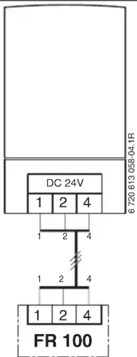
Fig. 11 FR 100 connected via the analogue 1-2-4 interface.

The third contact enables the controller to recognise that it is not connected via the BUS link but instead via the analogue 1-2-4 interface.
4 Commissioning (contractors only)
For correct commissioning, it is essential that the following steps are carried out in the order shown.
- Set the DIP switch on IPM 1 and IPM 2 in accordance with the details in the instructions supplied.
- Switch the system ON.
- Program additional room temperature controllers FR 10 (not permissible in Germany) or FR 100 in accordance with the details in the manual supplied.

The functions of the controls and the meanings of the symbols on the display are explained on pages 2 and 3.
- When commissioning for the first time or after a complete reset (all settings have been reset), you need to select the display language:
- Turn to select the language and press to confirm. (For how to change the language → chapter 6.4.4 on page 49.)
-
If the power reserve has run out, set the time and date as follows:
-
Turn to select the hour and press to confirm.
- Turn to select the minutes and press to confirm.
- Turn to select the year and press to confirm.
- Turn to select the month and press to confirm.
-
Turn to select the day and press to confirm. (For how to change the date and time → chapter 6.4.1 on page 49.)
-
Set the code for the heating circuit (only FR 100 with BUS connection)

Only one FR 100 or FR 10 can be assigned per heating circuit and per code (not permissible in Germany).
- If the controller is to control heating circuit HC_1 and DHW heating: Identification CH circuit select code 1 with and confirm with
-
If the controller is to control heating circuit HC_2 10 : Identification CH circuit with a code between 2 and 10 and confirm with
-
During commissioning, automatic system configuration starts immediately after entry of the date and time.
-
Wait for 60 seconds and then follow the instructions displayed.
-
If automatic system configuration does not start of its own accord, start it from the menu chapter 8.2 on page 58.
-
Switch off automatic Auto switch between GMT - BST → chapter 6.4.1 from page 49
- Adjust other settings to suit the current system, chapter 6 starting on page 30 and chapter 8 starting on page 54.
- Fill and vent the solar thermal system according to its documentation and prepare it for commissioning as described in chapter 8.4 on page 60.
- Adjust other settings to suit the current solar thermal system, chapter 8.5 starting on page 60.
-
Commission the solar thermal system, → chapter 8.5.1 on page 61.
-
Inform the system user about the functions and method of operation as follows:
- The contractor explains to the customer how the heating appliance and controller work and how to operate them.
- Inform the user about the assigned heating circuits, e.g. heating circuit 1 is for the radiator heating system and heating circuit 2 for the underfloor heating system.
- Explain to the user how to operate the system on a day-to-day basis, e.g. time, operating modes for the heating circuits, DHW temperature, time programs for heating circuits and DHW.
- Explain how to use the thermal disinfection function and the associated risk of scalding.
- Hand all documents provided over to the user.
- Complete the commissioning report, → chapter 12 on page 76.
5 Operation
Introduction
With the FR 100 / FR 110 heating controller, you can automatically control the room and DHW temperatures with a heating and DHW program created according to your own individual requirements.
![[°C] [ ] 6 720 612 481-70.1J](/content/2026/06/1252785/images/77d7ce8b26460ca588e4dcde3401d49f40f7c2ea868f95761778515b987c6644.jpg)
Fig. 12 Example of heating program

If the FR 100 is connected to the heating appliance via the analogue connection (1-2-4 interface), only the heating program, the parameters for central heating and the controller-specific settings (e.g. Time) are active. DHW, solar and system-specific settings (e.g. System info) are not available. In this case, DHW can be switched directly via the heating appliance.
Once the controller is set to your personal preferences, you hardly need the menus for “everyday use”. Nevertheless, it is useful to be familiar with basic navigation through the menus.
Therefore, you should read the whole of the following sections 5.1 and 5.2 below and adjust a heating or DHW program to your own requirements as described in chapter 5.2.2.
Why not take the trouble – it will be worth your while! The procedure for changing a switching point will illustrate everything you need to know about navigating through the menus and entering settings. You can then make all other settings in
the same way with the aid of the information in chapters 6 and 8.
The description of the menus reflects the arrangement of the menu points in the heating controller. The tables in chapters 6.1, 7 and 8.1 show the entire menu structure. They also provide details of the setting ranges and factory settings for all adjustable parameters. More information on the menu points can be found in sections 6.2 to 6.5 for the user level, and sections 8.2 to 8.8 for the contractor level.
The description of a menu points starts with its menu path. That shows you how to reach the menu point concerned by navigating through the menus. The individual menu levels are separated by symbol >, e.g. holiday > start.
Some menu points are dependent on others. In such cases, a page reference directs you to a description of the menu point on which it depends. Make use of such page references to other menu points. They will help you to understand associated functions.

The controller provides the option of setting the required room temperature for the operating mode concerned.
5.1 Heating and DHW programs
5.1.1 General
The programs for heating and DHW enable you to achieve maximum energy savings while still enjoying optimum comfort in terms of room temperature and availability of hot water. That is achieved, for instance, by deactivating DHW heating at times when nobody requires hot water.
5.1.2 Weekly programs
All time programs are set up to repeat every seven days. In the program memory you can store 6 switching times per day in each program, i.e. a total of up to 42 switching times.
To simplify programming, you can set switching times for groups of days as well as for individual days.
The following groups of days are offered:
• All days
• Mon - Fri
- Sat + Sun
If, for example, you change and save a switching time for menu point Mon - Fri, that change is simultaneously applied to every day from
Monday to Friday.
5.1.3 Structure of programs
Programs for heating and DHW are always structured in the same way. Up to six switching points (switching times) can be specified. A change of operating mode is specified for each switching time. The specified operating mode applies until changed by the next switching time.
Heating programs
Heating programs control central heating operation. There are three modes for heating operation:
- Comfort

- Economy

- Frost (frost protection)

-or-
Individual temperature levels:
• 5 °C to 30 °C in 1 °C increments.
For each of these operating modes, there is a set room temperature stored in the FR 100 / FR 110 heating controller ( chapter 5.4.1, page 29).
There are a total of six program spaces (A to F) available in the memory for heating programs. Each heating program contains the switching times for one week (weekly program). You can activate one heating program at a time.

Having several stored heating programs simplifies the change from one heating program to another, e.g. if your job involves periods when you work different shifts (night shift/day shift), or for holiday periods.
DHW programs
Domestic hot water programs operate differently according to the type of DHW system:
- With combi boilers (boilers which produce hot water instantaneously on demand), the DHW program switches between the following operating modes:
- On: if the eco button on the heating appliance is not lit, hot water is available very quickly on demand (comfort mode).
- Off: the built-in plate heat exchanger in the heating appliance is not kept constantly hot (eco mode); as a result energy is saved. In eco mode, the hot tap has to be run for a short while before the water becomes hot.
- If the DHW cylinder and FR 100 are directly connected to the heating appliance, the DHW program switches between the following operating modes:
- On: Cylinder heating enabled (temperature in accordance with setting on heating appliance).
- Off: Cylinder heating blocked.
- With appliances connected to a DHW cylinder and FR 110, the DHW program specifies the required water temperature (set temperature).
- If the temperature measured in the DHW cylinder is below the set temperature, the cylinder is reheated.
- Once the set temperature is reached (or exceeded), cylinder reheating is stopped.

If the DHW program changes from a higher to a lower temperature, the water in the cylinder will not immediately cool to the lower temperature, i.e. water at a higher temperature will continue to be available for some time. However, the cylinder will not be reheated until the temperature falls below the new set temperature.
The DHW circulation program specifies when a connected DHW circulation pump for domestic hot water runs.
5.2 Setting programs

The functions of the controls and the meanings of the symbols on the display are explained on pages 2 and 3.
5.2.1 Display views and menu navigation
The user interface of the FR 100 / FR 110 room temperature-dependent heating controller is implemented as a so-called "menu". Within that menu, the various functions are arranged in a hierarchical structure. For greater clarity, the menu is subdivided into three sections (MAIN MENU, INFO, INSTALLER SETTINGS). Each section can be accessed by its own button. The entire menu structure is shown in tabular form in chapters 6.1, 7 and 8.1.
To navigate through the menu:
- Press menu to open MAIN MENU. From any point within the MAIN MENU, press to go back to the standard display.
- Press info to open the INFO menu. From any point within the INFO menu, press info to go back to the standard display.
- Hold down for at least 3 seconds to open the INSTALLER SETTINGS menu. From any point within the INSTALLER SETTINGS menu, press to go back to the standard display.
- The selected menu point/parameter is displayed in inverse, i.e. white on black.
- Arrows in the left margin indicate that there is more information than can be shown on the display at once. It can be viewed with
- opens the submenu associated with the selected menu point/parameter or activates editing mode for the parameter (the parameter setting starts flashing).
- A flashing parameter setting (e.g. switching time or operating mode)
- can be changed with .†○
- can be deleted (reset to the default) with
- is stored with . _ok
- remains unchanged if any other key apart from is pressed.
- To return to the next menu up from a submenu:
- Highlight menu point and Back confirm with or
- press
5.2.2 Setting and changing switching times and operating modes
The way in which switching times and operating modes are set is always the same; the only differences are due to the various operating modes for each switching point.
The unit is supplied with programs for heating and DHW already stored. It may also be that your heating installer has adjusted the programs to suit your requirements (lifestyle).
Changing (moving or deleting) a single switching point

The example below shows all the steps required to change a switching point in a heating program. If, instead, you want to change a switching point in a DHW program, open the DHW program concerned (menu path: Domestic hot water > DHW programme > Edit) and change the switching point in the same way.
▶ Open flap.
The standard display continues to be shown.
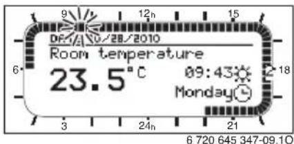
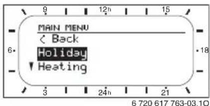
▶ Press

The display lighting switches on and the main menu is displayed.
24 | Operation
▶ Turn until menu point Heating is highlighted.

▶ Press

The Heating menu is selected and the title bar shows the current menu name (in this case HEATING).
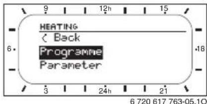
▶ Turn ⬆ until menu point Programme is highlighted.
▶ Press

The Programme menu is selected and the header shows the current menu title (in this case HEATING PROGRAMME).

▶ Turn 10 until menu point Edit is highlighted.
▶ Press

The Edit menu is selected and the header shows the current menu title (in this case EDIT HEATING PROGRAMME).
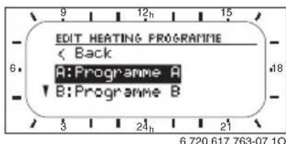
▶ Turn until the required heating program is selected (e.g. A:Programme A).
▶ Press

The heating program (e.g. A:Programme A) is selected and the header shows the current menu title (EDIT PROGRAMME A).

▶ Turn until the required day (or group of days) is highlighted (e.g. Monday).
The segment ring always shows you the heating program if you highlight just one specific day (e.g. Monday) or if, on a group of days, all switching times are identical for every day in that group (e.g. all switching times for Mon - Fri are identical).

▶ Press to confirm the menu point Monday.
The next submenu (EDIT PROGRAMME A MON) showing the programmed switching times and operating modes P1 to P6 is displayed.

▶ Turn ⬆ until menu point P1 is highlighted (= switching time 1).
▶ Press

The switching point and corresponding segment in the segment ring start to flash.
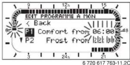
▶ Turn until the required switching time is displayed (e.g. 05:30 h).
The segment ring always shows the effect of the switching time change on the heating program.

▶ Press

The switching point is saved. The associated operating mode now starts flashing on the display.
▶ Turn until the required operating mode (e.g. Economy) or temperature is shown.
The segment ring always shows the effect of the change on the heating program.

▶ Press

The operating mode is saved. Setting of P1 is now complete.
▶ You can now:
- change more switching times and operating modes in the same way, or
- finish programming and return to the standard display by pressing menu
Using groups of days when programming
In many cases, you may want to programme the same switching times for several days of the week, say for all working days. Equally, you may also want a different program for just one of those days.
Using the groups of days when programming enables you to complete the process in only a few steps.
For a group of days, e.g. Mon - Fri, programme the switching times and operating modes that should apply to the majority of the days in this group of days.
▶ Then change the switching times for the days that are different.
Copying pre-saved heating programs
There are eight pre-saved heating programs permanently stored in the heating controller memory. They cannot be directly applied to a heating circuit.
To be able to use the pre-saved heating programs, you must copy them to one of the memory locations for heating programs (A to C), where you can also adapt them if necessary ( chapter 5.2.2).

You can also copy any of the programs A to C or D to F to another location as a template.
Select the location to which the program is to be copied (A to F):
▶ Menu: Heating > Programme > Edit > A:Programme A ... F:Programme F.
▶ Press twice. Function Copy from preset programme is called up; the word No flashes.

▶ Turn until the last line of the display shows the heating program to be copied (e.g. Full weekday worker).
▶ Press ☐. The heating program has now been copied.
Resetting an entire program (overwriting with factory settings)
The heating controller is supplied with programs for heating and DHW already stored in the memory ( chapter 13 on page 77).
Overwrite one of your own heating programs, A to F, as follows:
▶ Call up the relevant program (e.g. menu: Heating > Programme > Edit > C:Programme C or menu: Domestic hot water > DHW programme > Edit).
▶ Turn until menu point Reset factory settings is highlighted.
▶ Press The program has now been reset to the factory settings.
Resetting all settings (for heating contractors only)
This function resets all settings of MAIN MENU and INSTALLER SETTINGS to their factory settings. Following such a reset, your heating contractor will need to recommission the system!
If the standard display is set:
▶ Simultaneously press and hold and until the following warning message appears:

▶ Continue holding and until the following message appears:

▶ Press ☑ All settings have now been reset to their defaults with the exception of the date and time, which remain unchanged.
5.3 Manually setting operating modes
The information shown in the standard display and the operation only apply to the associated heating circuit.
5.3.1 Selecting the operating mode for heating

In standard operation, always leave the rotary selector in the auto position. By using correctly set heating programs, you can save energy without compromising on comfort.

Automatic mode (factory setting)
Automatic changeover between operating modes Comfort ✪ / Economy Ⓐ / Frost ✪ according to the active heating program.

Constant heating
The controller constantly maintains the room temperature set for Comfort ✿ mode.

Constant economy
The controller constantly maintains the room temperature set for Economy Ⓐ mode.

Constant frost protection
The controller constantly maintains the room temperature set for Frost ✿ mode.
5.3.2 Advancing heating mode before the programmed time (bringing forward the next switching point)
This function brings forward the time at which operating mode Comfort ✪ / Economy Ⓗ / Frost ✪ or the specified room temperature set for the next switching point was to become active.

The change applies only to the day on which you activate the function.
▶ The function can be used in situations such as going to bed earlier, being away from home longer or coming back earlier.
▶ If you are going to be away from home for several days, e.g. on holiday, you should use the holiday function, → chapter 5.3.4, page 28.
This function is only available when anode is switched on.
▶ Briefly press to bring forward the next switching time and the associated operating mode Comfort ✪ / Economy ⬇ / Frost ✪ for the selected heating circuit to the current time.
The segment ring and header show the modified settings.
-or-
▶ Press and hold and simultaneously turn to change the next switching point. The segment ring and header show the modified settings.
To undo the change to the switching point:
▶ Press Ⅲ briefly again.
5.3.3 Changing DHW mode (time-limited)

You can use this function if you need hot water outside the programmed switching times.
▶ Press and release to activate DHW heating immediately.
- The DHW cylinder is heated up to the temperature set in the DHW program for 60 minutes.
- With a combi boiler, comfort mode is activated for 30 minutes.
To undo the change to DHW mode:
▶ Press briefly again.
5.3.4 Holiday program
You can use this function if you want to set a constant operating mode for several days (e.g. Frost *) without changing the heating programs.
When the holiday program is active, the heating circuits and DHW heating are operated according to the operating mode set in the holiday program (frost protection is automatically provided).
▶ Press menu
The display lighting switches on and the main menu is displayed.

▶ Press 1ok .
The holiday menu is selected and the header shows the current menu title (in this case Holiday).
▶ Press . The display changes to the holiday menu and Start is selected.
Now you can enter the date on which you want the holiday program to start. Enter the year, month and day one after the other and confirm each entry with
▶ Turn until End is selected.
▶ Press ok
Now you can enter the date on which you want the holiday program to end. Enter the year, month and day one after the other and confirm each entry with 1_k
▶ Turn until End is selected.
▶ Press ok
Now you can enter the date on which you want the holiday program to end. Enter the year, month and day one after the other and confirm each entry with

If you have set the holiday program to start on today's date, it will start immediately. If the date is in the future, the holiday program will start at 00:00 h on the set start date. It will end at 23:59 h on the set end date.
Programming of the holiday program is now complete. If required, you can adjust the heating and DHW modes. The following modes are set by default:
• Heating system: operating mode Frost
- Domestic hot water: operating mode Off ^1) or 15 °C ^2) .
- DHW circulation pump: operating mode Off.
• Thermal disinfection: operating mode Off.

When the holiday program is active, the standard display shows and, for example, HOLIDAY UNTIL 30.09.2010.
To cancel the holiday program early:
▶ Select menu Holiday > Start.
▶ Press rotary selector and then press
The display shows ::-:-:-.
▶ Press rotary selector to store the setting.
1) DHW heating by combi boiler or with FR 100 via DHW cylinder
2) DHW heating via DHW cylinder (only FR 110)
5.4 Changing the set room temperature

The controller provides the option of setting the required room temperature for the operating mode concerned.
5.4.1 Permanently changing the set room temperature
The following temperatures are stored as the factory settings for the set room temperature:
- Operating mode Comfort ⚙: 21 °C
• Operating mode Economy Ⓐ: 15 °C - Operating mode Frost ⚙: 5 °C
The heating controller controls the heating system so that actual room temperature is kept as close as possible to the set room temperature, subject to the set operating mode (in autole subject to the active heating program and the time).
If you wish to permanently alter the set room temperature, proceed as follows:
- Call up menu Heating > Parameter > Heating levels.
▶ Set the temperature for each operating mode ( chapter 6.2.2, page 40).
5.4.2 Changing the set room temperature for a limited period
▶ Set the required room temperature with . ♂ While you are changing the set room temperature, the display shows the required room temperature.
- If the operating mode selector is set to auto:
The new temperature applies until the next switching point.
- If the operating mode selector is set to / ① : The new temperature applies until the selector position is changed.
6 Adjusting the MAIN MENU
Detailed instructions on navigating through the menu structure, programming, deleting settings and resetting to the factory settings are provided in chapter 5.2 starting on page 22.
6.1 Overview and adjustment of the MAIN MENU
The tables below provide the following:
- An overview of the menu structure (column 1). The menu depth is identified by various shades of grey.
For example, in menu Heating > Programme submenus Edit and View are on the same level. - An overview of the factory settings (column 2), e.g. for resetting individual menu points to the default.
- An overview of the setting ranges of the individual menu points (column 3).
- Space for making a note of your personal settings (column 4).
- References to the detailed descriptions of the individual menu points (column 5).

The menu points are only shown if the system components are installed and/or active. Some menu points are not shown because they are switched off by a setting for another menu point.
▶ Always set or skip menu points in order. In that way, subsequent menu points will be automatically adjusted or not shown.
6.1.1 MAIN MENU: Holiday
| Menu structure Holiday Factory | setting Setting range | Personal setting | Description from page | |
| Start - - . - - . - - - - | Today ... 31.12.2099 | (in increments of one day/month/year) | 28 | |
| End - - . - - . - - - - | Start date ... 31.12.2099 | (in increments of one day/month/year) | ||
| Heating Frost Frost | Economy | Comfort | Auto | ||||
| Domestic hot water Off | ^1) | Off | Auto | On ^1) | ||
| 15 ^^2) | 15 °C ... 60 °C | Auto | |||
| DHW circulation pump Off Off | Auto | On | ||||
| Thermal disinfection | Off Off | On | |||
1) DHW heating with FR 100 / FR 110 and combi boiler or with FR 100 via DHW cylinder
| Menu structure Heating Factory setting Setting range | Personal setting | Description from page | ||||||
| Programme - - | - | 37 | ||||||
| Activate A:Programme A | (switching times from program Home all day) | A:Programme A ...F:Programme F(program title can be changed) | - | |||||
| Edit - | - | - | ||||||
| A: Programme A ...C: Programme C | - | - | - | |||||
| Copy from preset programme | No No | A:Programme A ...C:Programme C (program title can be changed) | AM weekday worker | PM weekday worker | Full weekday worker | AM+PM weekday worker | Home all day | Home all day, early | Home all day, late | Senior citizens | - | ||||||
| All days → Tables from | page 77 | → Tables from page 79 | → Tables from page 81 | |||||
| P1, P2 ... P6 | ||||||||
| Mon - Fri | ||||||||
| P1, P2 ... P6 | ||||||||
| Sat + Sun | ||||||||
| P1, P2 ... P6 | ||||||||
| Monday, Tuesday ... Sunday | ||||||||
| P1, P2 ... P6 | ||||||||
| Reset factory settings | No No | Yes | |||||||
| Programme name | As selected in the Edit menu,e.g.Programme A | Changing the program title | ||||||
| Menu structure Heating | Factory setting | Setting range | Personal setting | Description from page | |||
| D: Programme D ...F: Programme F | - | - | - | 37 | |||
| Copy from preset programme | No No | D:Programme | F:Programme F (program title can be changed) | - | ||||
| All days → Tables from | page 77 | → Tables from page 79 | → Table on page 81 | ||||
| Mon - Fri | |||||||
| Monday, Tuesday ... Sunday | |||||||
| Reset factory settings | No No | Yes | ||||||
| Programme name As se | selected in Edit menu, e.g. Programme D | Changing the program title | |||||
| View | - | - | |||||
| A: Programme A ...F: Programme FAM weekday workerPM weekday workerFull weekday workerAM+PM weekday workerHome all dayHome all day, earlyHome all day, lateSenior citizens | All days All days | Mon - FriSat + SunMonday, Tuesday... Sunday | - | ||||
| Parameter | - | - | 40 | ||||
| Heating levels - - | - | ||||||
| Comfort | 21.0 °C | 7.0 °C ... 30.0 °C(higher than Economy) | °C | ||||
| Economy | 15.0 °C | 6.0 °C ... 29 °C (higher than Frost and lower than Comfort) | °C | ||||
| Frost | 5.0 °C | 5.0 °C ... 28 °C(lower than Economy) | °C | ||||
6.1.3 MAIN MENU: Domestic hot water
| Menu structureDomestic hot water 1) | Factory setting Setting range | Personal setting | Description from page | |||
| DHW and DHW circulation pump 1) | Separate programmes | Separate programmes | As heating programme | 40 | |||
| DHW programme^2) | - | - | - | |||
| Edit - | - | - | ||||
| All days → Table on | page 83 | → Table on page 83 | → Table on page 83 | |||
| P1, P2 ... P6 | ||||||
| Mon - Fri | ||||||
| P1, P2 ... P6 | ||||||
| Sat + Sun | ||||||
| P1, P2 ... P6 | ||||||
| Monday, Tuesday ... Sunday | ||||||
| P1, P2 ... P6 | ||||||
| Reset factory settings No No | Yes | ||||||
| View - | - | - | ||||
| All days | Mon - Fri | Sat + Sun | Monday, Tuesday ... Sunday | - | - | - | |||
| DHW circ pump prog ^2)3) | - | - | - | 46 | ||
| Edit - | - | - | ||||
| All days → Table on | page 84 | → Table on page 84 | → Table on page 84 | |||
| P1, P2 ... P6 | ||||||
| Mon - Fri | ||||||
| P1, P2 ... P6 | ||||||
| Sat + Sun | ||||||
| P1, P2 ... P6 | ||||||
| Monday, Tuesday ... Sunday | ||||||
| P1, P1 ... P6 | ||||||
| Reset factory settings No No | Yes | ||||||
| View - | - | - | ||||
| All days | Mon - Fri | Sat + Sun | Monday, Tuesday ... Sunday | - | - | - | |||
| Menu structureDomestic hot water 1) | Factory setting | Setting range | Personal setting | Description from page | |
| Parameter 3) | - | - | - | 47 | |
| Cylinder temp at heating level Comf. | 60 °C 15 °C ... 60 °C °C | ||||
| Cylinder temp at heating level Eco | 50 °C 15 °C ... 60 °C °C | ||||
| DHW priority Priority Priority | Conditional priority | ||||
| DHW circ pump cycles 4/h 1/h ... 7/h /hour | |||||
| Thermal disinfection - - - | 48 | ||||
| Operating mode Manual Manual | Auto | |||||
| Operating status Not running | Not running | Start now | ||||
| Running | Running | Stop | ||||
| Time | 01:00 h | 00:00 h ... 23:45 h | hours | ||
| Time interval | 7 days | 1 day ... 30 days | days | ||
1) Only FR 110 or FR 100 with code 1
2) Only with "Separate programmes"
3) Only with FR 110
6.1.4 MAIN MENU: General settings
| Menu structureGeneral settings | Factory setting Setting range | Personal setting | Description startson page | |
| Time and date - - - | ||||
| Time - - : - - 00:00 ... 23:59 (in steps of hours, minutes) | minutes) | - | 49 | |
| Date - - . - - . - - - | 01.01.2005 ... 31.12.2099(in increments of one day/month/year) | - | ||
| Auto switch between GMT - BST ^1) | Yes Yes | No | |||
| Time adjustment 0.0 sec/week - 60.0 sec/week ... | +60.0 sec/week | sec/week | ||
| Display format | - - - | |||
| Date | DD.MM.YYYY | DD.MM.YYYY or MM/DD/YYYY | ||
| Display contrast | According to factory test | 25 % ... 75 % | % | |
| Information at top of display | Without ISM or cylinder: Date | Date | Required room temp | ||
| Without ISM, with cylinder: Cylinder temperature | Cylinder temperature | Date | Required room temp | |||
| With ISM and cylinder: Solar pump status | Solar pump status | Solar yield | Required room temp | Date | Cylinder temperature | |||
| With ISM but without cylinder: Solar pump status | Solar pump status | Solar yield | Required room temp | Date | |||
| Key lock | Off | Off | On | ||
| Language | English | English | Deutsch | Francais | Nederlands | ||
1) Auto switch between GMT - BST always switch off (select "No").
6.1.5 MAIN MENU: Solar
| Menu structure Solar | Factory setting | Setting range | Personal setting | Description startson page |
| T2: Max. solar cylinder temperature | 60 °C | 15 °C ... 90 °C | °C | 50 |
| Optimizing influence DHW ^1) | 0 K | 0 K (= function off) ... 20 K | K | 50 |
1) Only available with FR 110 and if the collector area has been set at the contractor level.
6.2 Heating program
Main menu: Heating

Set the flow temperature controller on the heating appliance to the maximum required flow temperature.
6.2.1 Time programs for heating
Heating programs control central heating operation. There are three modes for heating operation:
- Comfort

- Economy

- Frost (frost protection)

-or-
Individual temperature levels:
• 5 °C to 30 °C in 1 °C increments.
For each of the operating modes, there is a set room temperature stored on the FR 100/ FR 110 heating controller ( chapter 6.2.2, page 40).
There are a total of six program spaces (A to F) available in the memory for heating programs. Each heating program contains the switching times for one week (weekly program). You can activate one of the heating programs for each heating circuit.
A time/temperature profile with the specified temperatures for the operating modes
Comfort ✝ / Economy 📋 / Frost ✝ can be created for the heating programs A to C.
![[°C] 6 720 612 481-70.1J](/content/2026/06/1252785/images/aff97bcefa5c08d37c07b8e6c37e7fdeff769e04e1e329e3c39d107d7585e721.jpg)
Fig. 13 Example time/temperature profile with operating modes for heating programs A to C
An individual time/temperature profile with user-defined temperatures can be created for the heating programs D to F.
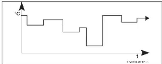
line
| t | C | | ------- | ----- | | Start | 0.5 | | Mid | 0.5 | | End | 0.5 |Fig. 14 Example time/temperature profile with user-defined temperatures for heating programs D to F

Having several stored heating programs simplifies the change from one heating program to another, e.g. if your job involves periods when you work different shifts (night shift/day shift), or for holiday periods.
Menu: Heating > Programme
Use this menu to create, change or activate a heating program for each associated heating circuit.
The heating programs are only active if the operating mode selector is set to auto
- Activate: Select and activate the heating program.
For menu structure and setting ranges → page 32.
Menu: Heating > Programme > Edit
Use this menu if you want to adapt a heating program with user-defined time/temperature level profile for the assigned heating circuit.
For menu structure and setting ranges → page 32.
Menu: Heating > Programme > Edit > A:Programme A ... F:Programme F
Use this menu to adapt the heating program of your choice.
- Copy from preset programme: Overwrites the selected heating program with an existing heating program of your choice.
- A:Programme A ... F:Programme F: Heating programs with user-defined time/temperature level profiles (program titles can be changed, see below)
- AM weekday worker ... Senior citizens: Pre-defined heating programs.
- Reset factory settings: Resets heating program to factory settings → page 26.
- Programme name: Changes title of heating program using and The 18 characters displayed can be individually replaced by selecting the letters and numbers offered.

To enter spaces:
▶ When the selected character is shown with a dark background, delete by pressing (space =_)
For menu structure and setting ranges → page 32.
Menu: Heating > Programme > Edit > A:Programme A ... C:Programme C > All days
Use this menu to set identical times for every day for the heating program of your choice.
- P1, P2 ... P6: Up to six switching times per day and three different operating modes
(Comfort ✉ / Economy Ⓐ / Frost ✉).
- The shortest switching interval is 15 minutes (= 1 segment).
- Deactivate switching times that are not required by deleting them.
- Skip switching times and operating modes that are not to be changed with or ♂
For menu structure and setting ranges → page 32.
Menu: Heating > Programme > Edit > D:Programme D ... F:Programme F > All days
Use this menu to set identical times for every day for the heating program of your choice.
- P1, P2 ... P6: Maximum of six switching times per day with temperatures from at least 5 °C to no more than 30 °C in 1 °C increments.
- The shortest switching interval is 15 minutes (= 1 segment).
- Deactivate switching times that are not required by deleting them.
- Skip switching times and operating modes that are not to be changed with or ↑○.
For menu structure and setting ranges → page 32.
Menu: Heating > Programme > Edit > A:Programme A ... C:Programme C > Mon - Fri
Use this menu to set identical times for the days Monday to Friday for the heating program of your choice.
• P1, P2 ... P6:
For explanation see A:Programme A .. above.
C:Programme C > All days.
For menu structure and setting ranges → page 32.
Menu: Heating > Programme > Edit > D:Programme D ... F:Programme F > Mon - Fri
Use this menu to set identical times for the days Monday to Friday for the heating program of your choice.
• P1, P2 ... P6:
For description see under D:Programme D ... above. F:Programme F > All days.
For menu structure and setting ranges
→ page 32.
Menu: Heating > Programme > Edit >
A:Programme A ... C:Programme C > Sat + Sun
Use this menu to set identical times for Saturday and Sunday for the heating program of your choice.
• P1, P2 ... P6:
For explanation see A:Programme A .. above.
C: Programme C > All days.
For menu structure and setting ranges
→ page 32.
Menu: Heating > Programme > Edit >
D:Programme D ... F:Programme F > Sat + Sun
Use this menu to set identical times for Saturday and Sunday for the heating program of your choice.
• P1, P2 ... P6:
For explanation see D:Programme D ...
above. F:Programme F > All days.
For menu structure and setting ranges
→ page 32.
Menu: Heating > Programme > Edit >
A:Programme A ... C:Programme C > Monday, Tuesday ... Sunday
Use this menu to set your custom heating program for individual days (e.g. Thursday: start every Thursday at the same time with the selected operating mode).
• P1, P2 ... P6:
For explanation see A:Programme A .. above.
C: Programme C > All days.

If, for example, the programming for
Thursday differs from the other days of the week, amongst the
option All days and Mon - Fri,
---- from --:-- appears for all values.
In other words there are no common switching times and operating modes for this selection.
For menu structure and setting ranges
→ page 32.
Menu: Heating > Programme > Edit >
D:Programme D ... F:Programme F > Monday, Tuesday ... Sunday
Use this menu to set your custom heating program for individual days (e.g. Thursday: start every Thursday at the same time with the selected operating mode).
• P1, P2 ... P6:
For description see under D:Programme D ... above. F:Programme F > All days.

If, for example, the programming for Thursday differs from the other days of the week, amongst the option All days and Mon - Fri, ---- from --:-- appears for all values. In other words there are no common switching times and operating modes for this selection.
For menu structure and setting ranges
→ page 32.
Menu: Heating > Programme > View
▶ Show switching times and associated heating program operating modes for All days, Mon -
Fri, Sat + Sun or the individual day of the week as a segment ring.
For menu structure and setting ranges
→ page 32.
6.2.2 Temperature levels for the operating modes
Menu: Heating > Parameter
Use this menu to permanently set the temperature levels for the 3 operating modes (Comfort ✉ / Economy 📋 / Frost ✉) to suit your personal preferences and your home.
Menu: Heating > Parameter > Heating levels
Use this menu to set the required room temperature for each of the operating modes:
- Comfort = maximum temperature required (e.g. when the living areas are occupied and the occupants require a comfortable room temperature). Solid segments on the display indicate the period for which this operating mode is active.
- Economy = average temperature required (e.g. when a lower temperature is sufficient or when the home is empty or everyone is in bed and you do not want the house to cool down too much). Empty segments on the display indicate the period for which this operating mode is active.
- Frost = minimum required temperature (e.g. when the home is empty or everyone is in bed and it is OK for the house to cool down). Consider any pets and plants.

Display of the segments for heating programs C, D and F (individual temperature profiles) is also dependent on the settings made here.
For menu structure and setting ranges
→ page 32.
6.3 DHW program
Main menu: Domestic hot water

The DHW program is only available for FR 100 with code 1 on a heating appliance with BUS-enabled Heatronic 3 and for FR 110 ( chapter 4 on page 18).

Set the DHW temperature controller on the heating appliance to the maximum required DHW temperature.
For FR 110: If a DHW cylinder is connected to the IPM downstream of the low loss header, turn the flow temperature controller on the heating appliance fully clockwise.

If the DHW program changes from a higher to a lower temperature, the water in the cylinder will not immediately cool to the lower temperature, i.e. water at a higher temperature will continue to be available for some time. However, the cylinder will not be reheated until the temperature falls below the new set temperature.
You can use this menu point either to ... ... Activate your individual DHW program (Separate programmes). Recommended for systems with several heating circuits.
- or -
... Link the DHW program to your heating program (As heating programme). That is useful if you frequently switch between different heating programs. The DHW program is then automatically adapted to suit.
Recommended for systems with one heating circuit.
- As heating programme (automatic mode together with the heating program):
With combi boiler:
DHW On as long as the heating circuit is in
Comfort mode and for 1 hour afterwards (run-on time).
Otherwise DHW Off.
With FR 100 and DHW cylinder at the heating appliance:
DHW On as long as the heating circuit is in
Comfort mode or changes to heating mode within the next hour.
Otherwise DHW Off.
With FR 110 and DHW cylinder:
1 hour before the heating circuit enters
Comfort mode, cylinder heating to the selected DHW temperature starts
(Cylinder temp at heating level Comf. ^1) ).
This setting remains active for as long as the heating circuit stays in Comfort ✿ mode.
If the heating circuit is in Economy
mode, then the cylinder will be held at the temperature selected under Cylinder temp at heating level Eco ^1) .
1) Set DHW temperature → chapter 6.3.5 on page 47
If the heating circuit is in Frost mode, then frost protection is also applied to the cylinder (15 °C fixed value).
With DHW circulation pump for DHW cylinders (only FR 110):
DHW circulation pump On and DHW circulation pump starts according to setting ( chapter 6.3.5 on page 47) if one of the heating circuits is in Comfort ✿ mode.
- Separate programmes (independent time programs):
Automatic changeover between DHW On ^2) / Off ^2) or different DHW temperatures ^3) and DHW circulation pump On / Off according to the stored programs.
DHW circulation pump starts according to setting ( chapter 6.3.5 on page 47).
For menu structure and setting ranges → page 34.
2) DHW heating with FR 100 / FR 110 and combi boiler or with FR 100 via DHW cylinder on the heating appliance
6.3.1 Time program for DHW with combi boiler
Use this menu if you wish to use a time program for DHW heating.
The time program is only programmable and active if Domestic hot water > DHW and DHW circulation pump > Separate programmes is set.
Use this menu if you wish to adjust a time program for DHW heating.
- Reset factory settings: Resets DHW program to factory settings → page 26.
For menu structure and setting ranges → page 34.
Menu: Domestic hot water > DHW programme > Edit > All days
Use this menu to set identical times for each day for the DHW program.
- P1, P2 ... P6: Maximum of six switching times per day and two different operating modes (On / Off).
- On: if the eco button on the heating appliance is not lit, hot water is available very quickly on demand (comfort mode). Solid segments on the display indicate the period for which this operating mode is active. - Off: the built-in plate heat exchanger in the heating appliance is not kept constantly hot (eco mode); as a result energy is saved. In eco mode, the hot tap has to be run for a short while before the water becomes hot. Empty segments on the display indicate the period for which this operating mode is active.
- The shortest switching interval is 15 minutes (= 1 segment).
- Deactivate switching times that are not required by deleting them.
For menu structure and setting ranges → page 34.
Menu: Domestic hot water > DHW programme > Edit > Mon - Fri
Use this menu to change the DHW program with identical times for Monday to Friday.
• P1, P2 ... P6: For description see All days above.
For menu structure and setting ranges → page 34.
Menu: Domestic hot water > DHW programme > Edit > Sat + Sun
Use this menu to set identical times for Saturday and Sunday for the DHW program.
• P1, P2 ... P6: For explanation see All days above.
For menu structure and setting ranges → page 34.
Menu: Domestic hot water > DHW programme > Edit > Monday, Tuesday ... Sunday
Use this menu to set the DHW program differently for individual days.
• P1, P2 ... P6: For description see All days above.
For menu structure and setting ranges → page 34.
▶ Shows switching times and associated operating modes for All days, Mon - Fri, Sat + Sun or the individual day of the week as a segment ring.
For menu structure and setting ranges → page 34.
6.3.2 Time program for DHW with DHW cylinder and combi boiler (FR 100)
Use this menu if you wish to use a time program for DHW heating.
The time program is only programmable and active if Domestic hot water > DHW and DHW circulation pump > Separate programmes is set.
For menu structure and setting ranges → page 34.
Use this menu if you wish to adjust a time program for DHW heating.
- Reset factory settings: Resets DHW program to factory settings → page 26.
For menu structure and setting ranges → page 34.
Menu: Domestic hot water > DHW programme > Edit > All days
Use this menu to set identical times for each day for the DHW program.
- P1, P2 ... P6: Maximum of six switching times per day and two different operating modes (On / Off).
- On: Cylinder heating enabled (temperature in accordance with setting on heating appliance). Solid segments on the display indicate the period for which this operating mode is active.
- Off: Cylinder heating blocked. Empty segments on the display indicate the period for which this operating mode is active.
- The shortest switching interval is 15 minutes (= 1 segment).
- Deactivate switching times that are not required by deleting them.
For menu structure and setting ranges → page 34.
Menu: Domestic hot water > DHW programme > Edit > Mon - Fri
Use this menu to change the DHW program with identical times for Monday to Friday.
• P1, P2 ... P6:
For description see All days above.
For menu structure and setting ranges → page 34.
Menu: Domestic hot water > DHW programme > Edit > Sat + Sun
Use this menu to set identical times for Saturday and Sunday for the DHW program.
• P1, P2 ... P6:
For description see All days above.
For menu structure and setting ranges → page 34.
Menu: Domestic hot water > DHW programme > Edit > Monday, Tuesday ... Sunday
Use this menu to set the DHW program differently for individual days.
• P1, P2 ... P6:
For explanation see All days above.
For menu structure and setting ranges → page 34.
▶ Shows switching times and associated operating modes for All days, Mon - Fri, Sat + Sun or the individual day of the week as a segment ring.
For menu structure and setting ranges → page 34.
6.3.3 Time/temperature level program for DHW (only with FR 110 and DHW cylinder)
Use this menu if you required a DHW program with user-defined time/temperature profile. The time/temperature program is only programmable and active if Domestic hot water > DHW and DHW circulation pump > Separate programmes is set.
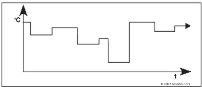
line
| t | °C | | ------- | ------ | | Start | 0.5 | | Mid | 0.5 | | End | 0.720613058-07.1R |Fig. 15 Example DHW program with time/temperature profile
For menu structure and setting ranges → page 34.
Use this menu if you wish to adjust a time program for DHW heating.
- Reset factory settings: Resets DHW program to factory settings → page 26.
For menu structure and setting ranges → page 34.
Menu: Domestic hot water > DHW programme > Edit > All days
Use this menu to set identical times for each day for the DHW program.
- P1, P2 ... P6: Maximum of six switching times per day with individual temperature levels (15 °C to 60 °C).
- If the temperature measured in the DHW cylinder is below the set temperature, the cylinder is reheated.
- Once the set temperature is reached (or exceeded), cylinder reheating is stopped.
- The shortest switching interval is 15 minutes (= 1 segment).
- Deactivate switching times that are not required by deleting them.

The segments on the display show the periods for the following DHW temperature demands: ≥ 50 °C – solid segments ≤ 20 °C – no segments other – blank segments
For menu structure and setting ranges → page 34.
Menu: Domestic hot water > DHW programme > Edit > Mon - Fri
Use this menu to change the DHW program with identical times for Monday to Friday.
• P1, P2 ... P6: For description see All days above.
For menu structure and setting ranges → page 34.
Menu: Domestic hot water > DHW programme > Edit > Sat + Sun
Use this menu to set identical times for Saturday and Sunday for the DHW program.
• P1, P2 ... P6:
For description see All days above.
For menu structure and setting ranges
→ page 34.
Menu: Domestic hot water > DHW programme > Edit > Monday, Tuesday ... Sunday
Use this menu to set the DHW program differently for individual days.
• P1, P2 ... P6:
For description see All days above.
For menu structure and setting ranges
→ page 34.
▶ Shows switching times and associated temperatures for All days, Mon - Fri, Sat + Sun or the individual day of the week as a segment ring.
For menu structure and setting ranges → page 34.
6.3.4 Time program for DHW circulation pump (only with FR 110 and DHW cylinder)
The DHW circulation program specifies when a connected DHW circulation pump for domestic hot water runs.
Menu: Domestic hot water > DHW circ pump prog
Use this menu if you wish to use a time program for the DHW circulation pump.
The time program is only programmable and active if Domestic hot water > DHW and DHW circulation pump > Separate programmes is set.
Menu: Domestic hot water > DHW circ pump prog > Edit > All days
Use this menu to set identical times for each day for the DHW program.
- P1, P2 ... P6: Maximum of six switching times per day and two different operating modes (On / Off).
- On: Circulation pump cycles as per setting (→ chapter 6.3.5 on page 47). Solid segments on the display indicate the period for which this operating mode is active.
- Off: The circulation pump is stopped. Empty segments on the display indicate the period for which this operating mode is active.
- The shortest switching interval is 15 minutes (= 1 segment).
- Deactivate switching times that are not required by deleting them.
For menu structure and setting ranges → page 34.
Menu: Domestic hot water > DHW circ pump prog > Edit > Mon - Fri
Use this menu to change the DHW program with identical times for Monday to Friday.
• P1, P2 ... P6: For description see All days above.
For menu structure and setting ranges → page 34.
Menu: Domestic hot water > DHW circ pump prog > Edit > Sat + Sun
Use this menu to set identical times for Saturday and Sunday for the DHW program.
• P1, P2 ... P6: For description see All days above.
For menu structure and setting ranges → page 34.
Menu: Domestic hot water > DHW circ pump prog > Edit > Monday, Tuesday ... Sunday
Use this menu to set the DHW program differently for individual days.
• P1, P2 ... P6: For description see All days above.
For menu structure and setting ranges → page 34.
Menu: Domestic hot water > DHW circ pump prog > View
▶ Shows switching times and associated operating modes for All days, Mon - Fri, Sat + Sun or the individual day of the week as a segment ring.
For menu structure and setting ranges → page 34.
- Cylinder temp at heating level Comf.:
This menu point is only active if Domestic hot water > DHW programme > As heating programme is set ( page 40). This is where you set the required DHW temperature for your DHW cylinder.
• Cylinder temp at heating level Eco:
This menu point is only active if Domestic hot water > DHW programme > As heating programme is set ( page 40). This is where you set the required reduced DHW temperature for your DHW cylinder.
- DHW priority:
This menu point is only active if Domestic hot water configuration in the system configuration has been set to Cyl on IPM ident. 3...10 ( chapter 8.1.1 on page 55). Use this menu if your heating is not to be switched off during cylinder heating (e.g. for buildings with limited insulation and low outside temperatures).
- Priority: The heating is switched off during DHW heating. The pumps stop and the mixers are closed.
- Conditional priority: During DHW heating the mixed heating circuits carry on heating, the pumps run and the mixers regulate to the required temperature. The non-mixed heating circuit is switched off to prevent overheating. Cylinder heating takes longer with Conditional priority.
This menu point is only active if the system has a DHW circulation pump. The DHW circulation pump stops during the DHW circulation pump Off phases. This menu point specifies how many times per hour the DHW circulation pump will cycle during the DHW circulation pump On phase. With the setting:
- 1/h to 6/h, each DHW circulation pump cycle lasts 3 minutes.
- 7/h, the DHW circulation pump runs continuously during the On phase.
For menu structure and setting ranges → page 34.
6.3.6 Thermal disinfection of hot water (with DHW cylinder only)
Menu: Domestic hot water > Thermal disinfection
This menu is only active if your domestic hot water is provided by a DHW cylinder. We recommend that you carry out thermal disinfection at regular intervals. For larger DHW systems, there may be a legal requirement for thermal disinfection.
If you have a combi boiler, please refer to the guidance in the boiler documentation.

NOTICE: Risk of scalding!
Hot water can lead to severe scalding.
▶ Only carry out thermal disinfection at times when the system is not normally in use.
▶ Inform occupants of the building of the danger of scalding and always monitor the thermal disinfection process.
- Operating mode:
- Auto: Thermal disinfection starts automatically according to the set starting conditions. Thermal disinfection can be switched on and cancelled manually.
- Manual: Thermal disinfection can be started from Operating status.
- Operating status:
- Not running: No thermal disinfection at present. Once-only thermal disinfection can be started by selecting Start now.
- Running: Thermal disinfection in progress. Thermal disinfection can be terminated by selecting Stop.
If Solar sys option E Thermal disinfection is switched on ( chapter 8.4 on page 60) and thermal disinfection is terminated by selecting Stop, a fault is indicated for 5 minutes if the disinfection temperature in the solar cylinder has not been reached (fault 54 chapter 9.1 from page 65).
- Time: Start time for automatic thermal disinfection.
- Time interval: Period until next start time for automatic thermal disinfection.

If you want to use automatic thermal disinfection (e.g. once a week), proceed as follows:
▶ Set the required time interval (e.g. 7d, i.e. 7 days).
▶ Set the required start time (e.g. 22:00).
▶ Set the operating mode to Auto on the day on which you want thermal disinfection to take place.
For menu structure and setting ranges → page 34.
6.4 General settings
6.4.1 Time and Date
Menu: General settings > Time and date
Use this menu if you want to correct the date and time.
- Time: Resets the time, e.g. if the mains power has been off for more than 12 hours.
- Date: see above Time. The current day of the week (e.g. Mo) is calculated automatically.

Auto switch between GMT - BST
▶ Switch automatic summer/wintertime changeover off.
- Time adjustment: Sets the adjustment factor for the time. The adjustment is carried out once a week.
Example:
- The time is out by approximately - 3 minutes a year
-- 3 minutes a year is equal to - 180 seconds a year
- 1 year = 52 weeks
-- 180 seconds ÷ 52 weeks
= -3.46 seconds a week
- Correction factor = +3.5 sec/week
For menu structure and setting ranges → page 36.
6.4.2 Display formats
Menu: General settings > Display format
Use this menu if you want to customise the display formats to suit your personal preferences.
- Date: Selects either DD.MM.YYYY or MM/DD/YYYY as date display format (D = digit for day, M = digit for month, Y = digit for year).
- Display contrast: Sets display contrast to between 25 % and 75 %.
• Information at top of display: Sets the required information to be shown on the top line of the standard display.
For menu structure and setting ranges → page 36.
6.4.3 Key lock
For menu structure and setting ranges → page 36.
- Key lock: Use this menu point to prevent unwanted operation of the key functions, e.g. by children.
- If a locked button is pressed when the Key lock is active and the standard display is shown, an appropriate message appears.

Changes to a different mode via the operating mode selector only become active when Key lock is reset.
▶ Resetting Key lock:
Hold down


simultaneously until the relevant message appears.
For menu structure and setting ranges → page 36.
6.4.4 Language
- Language: Use this menu point if you want to set a different language for the display.
For menu structure and setting ranges → page 36.
6.5 Solar settings
Main menu: Solar
Use this menu if you want to limit the cylinder temperature or optimise the set DHW and flow temperatures based on the available solar energy in your geographical region.
Limiting cylinder temperature
In order to store as much solar energy as possible, a high cylinder temperature is required.
Limiting the cylinder temperature prevents overheating of the domestic hot water. The temperature setting is transmitted by the ISM module during commissioning.

WARNING: Risk of scalding! If the cylinder temperature is higher than 60 °C.
▶ If the cylinder temperature limit is set to > 60 °C, install a thermostatic DHW mixer or the DHW comfort assembly (WWKG, accessories → Fig. 4 on page 13) in the DHW line.
▶ Set the DHW mixer unit to 60 °C max.
- T2: Max. solar cylinder temperature: Cylinder temperature > 60 °C in DHW cylinders only if outlet temperature is limited by thermostatic DHW mixer.
For menu structure and setting ranges
→ page 36.
Solar optimisation
In order to use as much solar energy as possible, the FR 110 heating controller can estimate the expected solar yield over the course of a day and take it into account when controlling the DHW. The heating appliance will then not be required to produce as much heat and will use less gas.
For more information for heating contractors
→ chapter 8.5.3 on page 62
- Optimizing influence DHW: Maximum reduction of set DHW temperature by effect of solar thermal system.
Example:
- Set DHW temperature = 60 °C
- Optimizing influence DHW = 15 K
- Set DHW temperature for heating appliance = 60 °C - 15 K
- Provided there is sufficient solar output available, the maximum reduction is set and the heating appliance heats the DHW to 45 °C, with the remaining 15 K being provided by the solar contribution.

Optimizing influence DHW does not start until a calibration phase of at least 30 days has been completed after commissioning of the solar thermal system. In that period, the FR 110 heating controller “learns” what level of solar yield is possible.
For menu structure and setting ranges
→ page 36.
7 Viewing information
Menu: INFO
This menu allows you to view a variety of system information.
Detailed instructions on navigating through the menu structure are provided in chapter 5.2 starting on page 22.

The menu points are only shown if the system components are installed and/or active. Some menu points are not shown because they are switched off by a setting for another menu point.
INFO menu overview
The table below provides the following:
- An overview of the menu structure (column 1). The menu depth is identified by various shades of grey. For example, menus Boiler and Heating system are on the same level.
- An overview of the various display options (column 2).
- Descriptions of the individual information items (column 3).
| Menu structure INFO Display (example) Description | |||
| Boiler | - | ||
| Heating mode possible Yes | No Shows whether heating appliance is ready for operation. | |||
| Current CH flow temperature | 55.0 °C Current heating appliance flow temperature. | ||
| Burner On | Off Burner status. | |||
| Heating pump On | Off Status of pump in heating appliance. | |||
| Maximum CH flow temperature | 75.0 °C Maximum flow temperature set on heating appliance. | ||
| Maximum domestic hot water temperature | 60.0 °C Maximum DHW temperature set on heating appliance. | ||
| Service required | Yes | No Shows whether a heating appliance service/inspection is required. | ||
| Menu structure INFO | Display (example) | Description | |
| Heating system - - | |||
| Identification CH circuit 1 Currently assigned heating circuit. | |||
| Operating mode Auto - Comfort | Auto - Economy | Auto - Frost | Comfort | Economy | Frost | Holiday - Auto | Holiday - Comfort | Holiday - Economy | Holiday - Frost | Current operating mode or special mode for the assigned heating circuit. | ||
| Required room temp 25.0 °C Required room temperature for the assigned heating circuit. | |||
| Current room temperature 22 0 °C Room temperature measured at the controller. | |||
| Required heating output 45 % Output requested by the controller (only in the case of analogue connection of the FR 100 via 1-2-4 interface). | |||
| Required CH flow temperature 75.0 °C Flow temperature for the assigned heating circuit calculated and requested by the controller. | |||
| Current CH flow temperature 47.0 °C | Actual flow temperature captured in the assigned heating circuit. | ||
| Heating pump On | Off | Switching state of the heating circuit pump in the assigned heating circuit. | ||
| Current mixer setting 85 % open | Current opening state of mixer in the assigned heating circuit. | ||
| Domestic hot water | -- | ||
| Operating mode Immediate DHW | Auto On | Auto Off | Holiday - Auto | Holiday On | Holiday Off | Current operating mode or special mode for DHW with combi boiler. | ||
| Required DHW temperature 60.0 °C | DHW temperature requested by controller. | ||
| Current DHW temperature 40.0 °C Current measured DHW temperature. | |||
| Domestic hot water status Running | Off | Current status of DHW heating. | ||
| Last thermal disinfection 1) Completed | Cancelled | Running | Status of last thermal disinfection. | ||
| Customer service 2) | - | - | |
| Phone number (Telephone number) | Telephone number of heating contractor (system installer). | ||
| Name (Name) Name of heating contractor (system installer). | |||
| Menu structure INFO | Display (example) | Description | ||
| Solar | ||||
| Standard system – Menu for | basic system component of solar thermal system. | |||
| T1: Temperature of collector group 1 | 80.0 °C Temperature measured by collector temperature sensor ( T_1 ). | |||
| T2: Temp at bottom of solar cylinder | 55.7 °C Temperature measured by bottom cylinder temperature sensor ( T_2 ) in solar cylinder. | |||
| SP: Collector grp 1 solar pump status | Running | Off Status of solar circuit pump (SP). | |||
| Collector group 1 shut down | Yes | No Shows whether safety shutdown of the solar circuit pump (SP) due to overheating of the collectors ( T_1 ) has occurred. | |||
| Solar cylinder status Fully charged | Partially charged | Charge status of solar cylinder. | |||
| SP: Coll grp 1 solar pump running time | 12463 h Solar circuit pump (SP) hours run since commissioning. | |||
| Thermal disinfection ^1) | – Menu for thermal disinfection part of the system. | |||
| PE: Therm disinfect pump status | Running | Off Status of thermal disinfection pump (PE). | |||
| Solar optimisation ^3) | – Menu for solar-assisted optimisation of conventional heating system. | |||
| Solar yield in last hour 120 Wh Solar energy yield in the last hour (a figure is only shown if correct parameters have been set on the solar optimisation menu, → chapter 8.5.3 on page 62). | ||||
| Solar yield today 2.38 kWh Solar energy yield for the current day. | ||||
| Solar yield overall | 483.6 kWh | Total solar energy yield since commissioning. | ||
| DHW temperature reduced by | 4.7 K | Current reduction of the set DHW temperature requested by the heating appliance as a result of the available solar energy. Does not start until at least 30 days after commissioning. | ||
| Faults | 40 Solar system03 FR 100EA heating appliance... | List of current faults. More detailed information can be displayed with [IMAGE] and [IMAGE] to confirm. | ||
1) For FR 100 only with DHW cylinder on the appliance.
2) Only available if a name or telephone number has been registered at the contractor level.
3) Only available if the collector area has been set at the contractor level.
8 Menu settings INSTALLER SETTINGS (for contractors only)

The INSTALLER SETTINGS menu is intended only for contractors.
▶ To open INSTALLER SETTINGS: Hold down menu for approx. 3 seconds.
Detailed instructions on navigating through the menu structure, programming, deleting settings and resetting to the factory settings are provided in chapter 5.2 starting on page 22.

The menu points are only shown if the system components are installed and/or active. Some menu points are not shown because they are switched off by a setting for another menu point.
▶ Always set or skip menu points in order. In that way, subsequent menu points will be automatically adjusted or not shown.
8.1 Summary and settings of the INSTALLER SETTINGS menu
The tables below provide the following:
- An overview of the menu structure (column 1). The menu depth is identified by various shades of grey.
For example, in menu Solar sys parameters submenus 1. Standard system and Solar optimisation are on the same level. - An overview of the factory settings (column 2), e.g. for the purposes of resetting individual menu points to their factory setting.
- An overview of the adjustment ranges of the individual menu points (column 3).
- Space for making a note of your personal settings (column 4).
- For locating detailed descriptions regarding the individual menu points (column 5).
8.1.1 INSTALLER SETTINGS: System configuration
| Menu structureSystem configuration | Factory setting | Setting range | Personal setting | Description from page |
| Connection type - BUS | 1-2-4 (only with FR 100) | 58 | |||
| Start automatic system configuration | No No | Yes | |||
| Domestic hot water configuration^1) | With FR 100: Combi boiler | No | Combi boiler | Cyl conn to boiler | ||
| Cyl conn to boiler | No | Combi boiler | Cyl conn to boiler | Cyl on IPM ident. 3 ... 10 | |||
| DHW circulation pump^2) | No No | Present | |||
| CH system configuration Unmixed without IPM | Unmixed without IPM | Unmixed with IPM | Mixed | |||
| Identification CH circuit 1 1 ... 10 (only FR 100 with BUS connection) | ||||
| ISM 1 No No | Present | ||||
| ISM 2 No No | Present | ||||
1) Only FR 110 or FR 100 with code 1
2) Only with FR 110
8.1.2 INSTALLER SETTINGS: Heating parameters
| Menu structure Heating parameters | Factory setting | Setting range | Personal setting | Description from page |
| Calibrate room temperature sensor | 0.0 K – 3.0 K ... | 3.0 K K | 59 | |
| Adjustment factor I 40 % 0 % ... | 100 % % | |||
| Amplification factor V | 80 % | 40 % ... 100 % | % | |
| Heat-up optimisation | No No | Yes | |||
| Maximum CH flow temperature | 75 °C | 30 °C ... 85 °C | °C | |
| Mixer running time | 140 s | 10 s ... 600 s | s |
8.1.3 INSTALLER SETTINGS: Solar system config
| Menu structureSolar system config | Factory setting | Setting range | Personal setting | Description from page |
| Solar sys option E Thermal disinfection | No No | Yes | 60 |
8.1.4 INSTALLER SETTINGS: Solar sys parameters
| Menu structureSolar sys parameters | Factory setting | Setting range | Personal setting | Description from page | |
| 1. Standard system - - - | 61 | ||||
| SP: ON temperature difference | 8 K 3 K ... 20 | K(not lower than “SP: OFF temperature difference” +1 K) | K | ||
| SP: OFF temperature difference | 4 K 2 K ... 19 | K(not higher than “SP: ON temperature difference” - 1 K) | K | ||
| T2: Max. solar cylinder temperature | 60 °C 15 °C | ... 90 °C °C | |||
| Maximum collector temperature | 120 °C 100 °C | ... 140 °C °C | |||
| SP: Collector grp 1 pump mode | Auto Auto | Manual On | Manual Off | ||||
| PE: Therm disinfect pump mode | Auto Auto | Manual On | Manual Off | 60 | |||
| Solar optimisation | 62 | ||||
| Collector group 1 area 0.0 m | ^2 | 0.0 m^2 ... 150.0 m^2 | m^2 | ||
| Collector group 1 type | Flat plate collector | Flat plate collector | Vac tube collector | |||
| Climate zone | 90 | 0 ... 255 | |||
| Optimizing influence DHW | 0 K 0 K (= function off) ... 20 K | K | |||
| Run solar system | No | No | Yes | 61 | ||
8.1.5 INSTALLER SETTINGS: Fault history
| Menu structureFault history | Factory setting | Setting range | Personal setting | Description from page |
| 01.01.201016:11Fault EA(example for last fault) | - | - | - | 64 |
| 25.09.201018:45FAULT 44 - IPM IDENT. 10(up to a maximum of 19 previous faults) | - | - | - |
8.1.6 INSTALLER SETTINGS: Cust service address
| Menu structureCust service address | Example | Setting range | Personal setting | Description from page |
| Telephone number | 012345 6789 | Max. 20 characters | 64 | |
| Name | Heating contractor | Max. 20 characters |
8.1.7 INSTALLER SETTINGS: System info
| Menu structureSystem info | Example Setting range | Personal setting | Description from page |
| Installation date 22.10.2010 | (activated on commissioning) | - | 64 |
| Boiler part number 7 777 777 777 | (data from heating appliance) | - | |
| Boiler date of manufacture 27.06 | 2010 (data from heating appliance) | - | |
| Controller part number and model | 7 777 777 777 FR 100 (fixed factory setting) | - | |
| Controller date of manufacture 27 | 7.06.2010(fixed factory setting) | - | |
| Controller software version JF11 | 12 (fixed factory setting) | - |
8.2 Configuring the heating system
Contractor level: System configuration

An example system is shown in chapter 2.5 on page 12. Other examples can be found in the instructions for the IPM or the technical guides.
Use this menu if you want to configure the system automatically or manually, e.g. when commissioning or making changes to the system.
- Connection type for the setting of the type of connection with the Heatronic 3 (only FR 100).
- Start automatic system configuration for starting automatic configuration.
- Domestic hot water configuration for the manual configuration of the DHW system (only for FR 100 with code 1 or FR 110).
- CH system configuration for the configuration of the assigned heating circuit.
- DHW circulation pump: This menu point is only active if a DHW circulation pump has been installed in the DHW system (only for FR 110).
- Identification CH circuit for the selection of the associated heating circuit (1 ... 10 - only FR 100)
When commissioning a heating system, proceed as follows:
▶ Code all BUS subscribers in accordance with their function (e.g. IPM 1 for heating circuit 1 etc.).
▶ Start automatic configuration.
▶ Check the other menu points under System configuration and, if necessary, adjust manually to suit the current system.

The heating system's solar thermal system must be configured manually ( chapter 8.4, page 60). Automatic configuration of the heating system does not configure the solar thermal system.
For menu structure and setting ranges → page 55.
8.3 Parameters for heating
Contractor level: Heating parameters

Set the flow temperature control on the heating appliance to the maximum required flow temperature.
Use this menu if you want to set the parameters for the associated heating circuit.
- Calibrate room temperature sensor:
- Fit a suitable precision instrument near FR 100. or FR 110. The precision instrument must not transfer any heat to the FR 100 or FR 110.
- Keep away from heat sources such as sunlight, body heat, etc. for 1 hour.
- Adjust the displayed room temperature correction value.
- Adjustment factor I
The Adjustment factor I is the rate at which a constant room temperature control deviation is corrected.
- ≤ 40 %: Set a lower factor to achieve minimal room temperature overshoot by more gradual correction.
- ≥ 40 %: Set a higher factor to achieve faster correction by a greater room temperature overshoot.
- Amplification factor V:
Subject to changes in room temperature, the Amplification factor V influences the heat demand.
- ≤ 80 %: Set a lower factor to reduce the influence on the heat demand. The selected room temperature is reached more slowly with only minimal overshoot.
- ≥ 80 %: Set a higher factor to increase the influence on the heat demand. The
selected room temperature is reached quickly with a tendency to overshoot.
- Heat-up optimisation:
- No: The heating program contains only switching times for the assigned heating circuit.
- Yes: The heating program contains times for the required room temperatures. The controller shifts the switching times for the heating automatically. When doing so, it is guided by the heating times required on previous days. In that way the controller is able to take account of seasonal outside temperature fluctuations.
While the modes Economy © / Frost ✉ are active, the conditions must remain constant for the lead room:
Keep the same doors closed.
Keep windows closed wherever possible. Heat the same rooms.
Do not adjust or cover radiators or valves.
→ More information can be found in chapter 10 on page 73.

If those conditions can not be maintained for several days:
▶ Operate the controller without heat-up optimisation.
• Maximum CH flow temperature:
Set Maximum CH flow temperature to suit the associated heating circuit.
- Mixer running time:
Set the Mixer running time to suit the runtime of the mixer servomotor used for the associated heating circuit.
8.4 Configuring the solar thermal system

The heating system's solar thermal system has to be configured manually. Automatic configuration of the heating system ( chapter 8.2, page 58) does not configure the solar thermal system.
Contractor level: Solar system config

An example system is shown in chapter 8.2 on page 58. Other examples can be found in the instructions for the ISM or the technical guides.
Use this menu if you want to set the thermal disinfection function for the solar thermal system.
- Solar sys option E Thermal disinfection for thermal disinfection
For menu structure and setting ranges → page 55.
8.5 Parameters for solar thermal system

Fill and vent the solar thermal system according to its documentation and prepare it for commissioning as described this chapter.
Contractor level: Solar sys parameters
The default parameter settings on this menu are suitable for many common system dimensions. Use this menu if you want to finely adjust the parameters to suit the installed solar thermal system.
- PE: Therm disinfect pump mode: Use this menu point to select the pump (PE) mode for thermal disinfection.
- Auto: Automatically controlled operation according to the set parameters.
- Manual On: Switches the pump permanently on (e.g. for function test when commissioning).
- Manual Off: Switches the pump permanently off (e.g. for servicing work on the pump without having to interrupt heating operation).
For menu structure and setting ranges → page 56.

The designations of the pumps and the temperature sensors, e.g. (PE) or (T1), are also used in the ISM installation instructions.
8.5.1 Commissioning the solar thermal system
Contractor level: Solar sys parameters
Before commissioning the solar thermal system you must:
▶ Fill and vent the solar thermal system.
▶ Check the parameters for the solar thermal system and, if necessary, finely adjust them to suit the installed system.
- Run solar system: Use this menu point to commission the solar thermal system.
- Yes: Solar thermal system is active. The ISM control outputs are enabled for automatic control purposes.
- No: Solar thermal system is not active. The ISM switching outputs are disabled for automatic control purposes but can be switched on manually.
For menu structure and setting ranges → page 56.
8.5.2 Parameters for the standard solar thermal system
Menu: Solar sys parameters > 1. Standard system
Use this menu to set the parameters for the solar thermal system if you are using it to provide domestic hot water.
- SP: ON temperature difference: Use this menu point to set the start temperature differential for the solar circuit pump (SP). If the difference between the collector temperature (T1) and the solar cylinder temperature (T2) rises above the set figure, the solar circuit pump (SP) is switched on.
- SP: OFF temperature difference: Use this menu point to set the stop temperature differential for the solar circuit pump (SP). If the differential between collector temperature (T1) and the solar cylinder temperature (T2) drops below the set value,
the solar circuit pump (SP) will be switched off.
- T2: Max. solar cylinder temperature: For a detailed description of T2: Max. solar cylinder temperature, → page 50.
- Maximum collector temperature: Use this menu point to set the maximum temperature at the collector temperature sensor ( T_1 ). If the temperature detected at the collector sensor ( T_1 ) rises above the set figure, operation of the solar circuit pump (SP) is disabled until the temperature drops back below the set figure.

At temperatures above 140 °C and system pressures < 4 bar, the heat transfer fluid in the collector evaporates. The solar circuit pump remains disabled until the collector has cooled to a temperature at which there is no more vapour in the solar circuit.
- SP: Collector grp 1 pump mode: Use this menu point to set the operating mode for the solar circuit pump (SP).
- Auto: Automatically controlled operation according to the set parameters.
- Manual On: Switches the pump permanently on (e.g. for venting the solar thermal system when commissioning).
- Manual Off: Switches the pump permanently off (e.g. for maintenance work on the solar thermal system without having to interrupt heating operation).
For menu structure and setting ranges → page 56.
8.5.3 Parameters for solar optimisation
Solar optimisation is performed automatically according to the available solar output. Calculation of the solar output requires specification of the installed collector area, the collector type and the climate zone in which the system is installed.
Menu: Solar sys parameters > Solar optimisation
Use this menu to set the parameters for solar optimisation.
- Collector group 1 area: Use this menu point to set the installed collector area for collector group 1.
| Collector type | Gross areaper collector in m^2 |
| FK 210 2.1 | |
| FK 240 2.4 | |
| FK 260 2.6 | |
| VK 180 1.8 | |
| FKT-1 2.4 | |
| FKC-1 2.4 | |
| FKB-1 2.4 |
Tab. 8 Gross collector areas
- Collector group 1 type: Use this menu point to set the installed collector type for collector group 1.
- Climate zone: Use this menu point to set the climate zone number for the geographical region in which the system is located.
- Find the location of your system on the climate zones map (→ Fig. 16) and enter the climate zone number.
- If your location is not shown on the map, leave the number as it is (factory setting is 90).
- Optimizing influence DHW: This parameter can also be set on on the main menu under Solar. A detailed description can be found on page 50.
For menu structure and setting ranges → page 56.

geo
| Region | Value | |--------|-------| | North America | 95 | | South America | 110 | | Europe | 115 | | Asia | 120 | | Africa | 105 | | Australia | 110 | | Central Asia | 100 | | Middle East | 105 | | Southeast Asia | 100 | | South Asia | 105 | | North America (top) | 90 | | South America (top) | 100 | | Central Asia (bottom) | 6720 | | Southeast Asia (bottom) | 645 | | Middle East (bottom) | 20.10 |Fig. 16 Map with the climate zones
8.6 Fault history
Contractor level: Fault history
Heating engineers can use this option to view the last 20 faults that have occurred on the system (fault date, source, code and description). The faults shown first may still be active.
For menu structure → page 56.
8.7 Viewing and entering the customer service address
Contractor level: Cust service address
- Phone number: The heating contractor can enter the phone number to call for customer service here.
- Name: The heating contractor can enter the address of the heating contractor responsible for customer service here.

To enter spaces:
▶ When the selected character is shown with a dark background, delete by pressing (space = _ )
For menu structure and adjustment range → page 56.
8.8 Viewing system information
Contractor level: System info
Shows a variety of system information:
- Installation date (automatically activated on commissioning)
- Boiler part number (fixed setting from heating appliance)
- Boiler date of manufacture (fixed setting from heating appliance)
- Controller part number and model (fixed factory setting)
- Controller date of manufacture (fixed factory setting)
- Controller software version (fixed factory setting)
For menu structure → page 57.
9 Troubleshooting
BUS device faults are indicated.
A heating appliance fault (e.g. EA fault) is displayed with the relevant information.
▶ Contact your installer.

For heating contractors:
▶ Rectify the fault in accordance with the details in the heating appliance documentation.
9.1 Troubleshooting using the display (for heating contractors only)
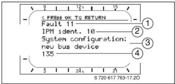
Fig. 17 Fault display
1 Fault number
2 BUS subscriber which detected the fault and reported it to the controller
3 Description of fault
4 Code or additional information about fault
The current fault is indicated on the controller:
▶ Identify the BUS subscriber affected by the current fault. The fault can only be rectified on the BUS subscriber from which the fault originates.
| Information displayed (→ Items 1, 3 and 4 in Fig. 17)Text Code Cause Remedy (by contractor) | |||
| Fault 01BUS communication fault | 10 IPM does not receive a set value from the heating controller. | Check BUS subscriber, BUS connection and repair lead break if necessary. | |
| 200 Heating appliance no longer reporting. | |||
| 201 Incorrect BUS subscriber connected. | Identify and replace incorrect BUS subscriber. | ||
| Fault 02Internal fault | 40 Incorrect module type detected. | Replace IPM. | |
| 41 Two identical codes have been entered at the IPM. | Switch system off and correct coding. | ||
| 42 DIP switch on IPM in intermediate position. | |||
| 43 DIP switch position has been changed since initialisation phase. | |||
| 100 ISM not responding. Check BUS connection and repair lead break if necessary. | |||
| Fault 02Internal faultSome parameters reset to factory settings due to EEPROM problem | 205 Some parameters reset to default. | Check parameter settings and readjust as necessary. Identify faulty controller and replace. | |
| Fault 02Internal faultFR110 can no longer control the CH system | 255 FR 100 / FR 110 can no longer control the heating system. | Identify faulty controller and replace. | |
| Fault 03Room temp sensor faulty | 20 The room temperature sensor built into FR 100 / FR 110 / FR 10 has suffered a break. | Identify faulty controller and replace. | |
| 21 There is a short circuit on the room temperature sensor built into the FR 100 / FR 110 / FR 10. | |||
| Fault 10System configuration: invalid | 190 Incorrect type of connection 1-2-4 set. | Check system configuration and set BUS as connection type. | |
| Fault 11System configuration: new BUS deviceNew ISM detected. Power up all ISMs simultaneously and start automatic system configuration. | 131 New ISM detected. Power up all | ISM simultaneously and start automatic system configuration. | |
| Fault 11System configuration: new BUS deviceNew IPM detected. Check and modify system configuration. | 135137 | New IPM detected. Check and adjusted system configuration. | adjust system configuration. |
| Fault 12System configuration: BUS device missingISM1/ISM2not detected. Check connection. | 170171 | ISM1/ISM2 no longer detected in spite of having been configured. | Check connection. |
| Fault 12System configuration: BUS device missingIPM for cylinder downstream of low loss header not detected. Check connection and identification. | 172173 | IPM for cylinder downstream of low loss header not detected. | Check and correct code. With the IPM isolated from the power supply. |
| Fault 12System configuration: BUS device missingIPM with identification x not detected.Check connection and identification. | 178179 | IPM with code x not detected | Check and correct code. With the IPM isolated from the power supply. |
| Fault 13System configuration: BUS device changed or replacedCheck system configuration for DHW or start automatic system configuration. | 157 | BUS subscriber changed or replaced. | Check system configuration for DHW heating or start automatic system configuration. |
| Fault 13System configuration: BUS device changed or replacedCheck system configuration for heating circuit x and connections on IPM for heating circuit x. | 159 | BUS subscriber changed or replaced. | Check system configuration for heating circuit x and IPM connections for heating circuit x. |
| Fault 14System configuration: incompatible BUS deviceDHW controlled by boiler. IPM control of DHW has no effect. | 117 | Incompatible BUS subscriber: Identify incompatible BUS subscriber and remove from the system. | |
| Fault 14System configuration: incompatible BUS deviceIPM for cylinder must be set to identification 3 or higher. | 118119 | Incompatible BUS subscriber: Set IPM for cylinder to code 3 or higher. | |
| Fault 19Unable to save parameter settings | 202 | BUS subscriber is configured but not available at present. | Check system layout, check system configuration, modify if necessary and set parameter again. |
| Information displayed (→ Items 1, 3 and 4 in Fig. 17)Text | Code | Cause | Remedy (by contractor) |
| Fault 30Mixer temperature sensor faulty | 7 M | xer temperature sensor (MF) connected to IPM faulty. | Check mixer temperature sensor (MF) and replace if necessary. |
| Fault 31External CH flow temperature sensor faulty | 6 C | common temperature sensor (VF) connected to the IPM faulty. | Check common temperature sensor (VF) and replace if required. |
| Fault 32Cylinder temperature sensor faulty | 8 C | linder temperature sensor (SF) connected to the IPM faulty. | Check cylinder temperature sensor (SF) and replace if required. |
| Fault 33Temperature sensors incorrectly connected | 20 C | cylinder temperature sensor (SF) and mixer temperature sensor (MF) are connected to the IPM. | Remove one of the temperature sensors (SF or MF). |
| 21 T | two common temperature sensors (VF) are connected to the IPM. | Remove one of the common temperature sensors (VF). | |
| 22 A | temperature sensor is connected to the IUM. | Remove the temperature sensor and insert a coding plug if necessary. | |
| Fault 34Temperature sensors connected and mode of operation do not match | 23 T | temperature sensors connected to the IPM and the associated operating mode do not match. | Check temperature sensors and associated operating mode and adjust if necessary. |
| Fault 40Temperature sensor T1 on collector group 1 faulty | 101 | short circuit on the sensor lead ( T_1 ). | Check temperature sensor ( T_1 ) and replace if necessary. |
| 102 | Break in the sensor lead ( T_1 ). | ||
| Fault 41Temperature sensor T2 at bottom of solar cylinder faulty | 103 | short circuit on the sensor lead ( T_2 ). | Check temperature sensor ( T_2 ) and replace if necessary. |
| 104 | Break in the sensor lead ( T_2 ). | ||
| Fault 50Solar pump jammed or air in system | 121 | solar circuit pump (SP) sticking due to physical blockage. | Unscrew and remove slotted screw on pump head and use a screwdriver to release pump shaft. Do NOT strike the pump shaft with the screwdriver. |
| Air in solar thermal system. Vent | solar thermal system and top up with heat transfer fluid if necessary. | ||
| Fault 51Incorrect temperature sensor type connected | 122 | Collector temperature sensor type used as cylinder temperature sensor ( T_2 ). | Use correct type of temperature sensor.→ Specification in ISM installation instructions. |
| 123 | Cylinder temperature sensor type used as collector temperature sensor ( T_1 ) | ||
| 132 | Temperature sensor type PTC 1000 used as cylinder temperature sensor ( T_2 ). | ||
| 133 | Temperature sensor type PTC 1000 used as collector temperature sensor ( T_1 ). | ||
| Fault 52Temperature sensors reversed | 124 | Temperature sensors ( T_1 and T_2 ) reversed. | Check the temperature sensors and swap the connections if necessary. |
| Fault 53Temperature sensor fitted in wrong location | 125 | Collector temperature sensor ( T_1 ) fitted on collector array inlet. | Fit collector temperature sensor ( T_1 ) close to collector array outlet. |
| Fault 54Temperature for thermal disinfection not reached in solar cylinder | 145 | Maximum temperature for solar cylinder too low. | Set higher maximum temperature for solar cylinder.→ Limiting cylinder temperature, page 50 |
| Pump rate of disinfection pump (PE) too low. | Set higher pump speed on disinfection pump (PE) or, if possible, open flow restrictor further. | ||
| Thermal disinfection cancelled manually before the required temperature was reached in the solar cylinder. | This is not a fault.Fault message is shown only for 5 minutes. | ||
| Fault 55Solar system not yet commissioned | 146 | Solar thermal system is not yet in operation. | Fill, vent and prepare solar thermal system for commissioning according to its documentation. Then commission solar thermal system. |
| Fault 56At least one pump/valve in manual mode | 147 | Pump (SP) in manual mode. Reset parameters for pump or valve to “Auto”. | |
| Information displayed (→ Items 1, 3 and 4 in Fig. 17) | |||
| Text | Code | Cause | Remedy (by contractor) |
| Fault 59Mass flow rate in solar system too high/low. | 201 | Mass flow rate in solar thermal system for collector group 1 is too high. | Set mass flow rate in solar circuit correctly (e.g. increase/reduce pump speed) or, if necessary, further open or close valve to the solar pumping station.Guide figure: 20 - 40 kg/m2 of collector area per hour.Check setting for collector area, type and climate zone on Solar optimisation menu. |
| 202 | Mass flow rate in solar thermal system for collector group 1 is too low. | ||
9.2 Troubleshooting without using display
| Problem Cause Remedy | ||
| Required room temperature not achieved. | Thermostatic valve(s) set too low. Set thermostatic valve(s) higher. | |
| Flow temperature controller on heating appliance set too low. | Set the flow temperature controller higher. | |
| Reduce influence of solar optimisation if necessary. | ||
| Air in the heating system. Bleed radiators and vent the heating system. | ||
| Required room temperature greatly exceeded. | Radiators become too hot. Set thermostatic valve(s) lower. | |
| Installation location of FR 100 / FR 110 unfavourable, e.g. external wall, close to window, in a draught etc. | Select a better installation location for FR 100 / FR 110 and ask your contractor to reposition it. | |
| Excessive room temperature fluctuations. | Temporary influence of external heat on the room, e.g. through solar radiation, lighting, TV, fireplace etc. | Select a better installation location for FR 100 / FR 110 and ask your contractor to reposition it. |
| Temperature rises instead of falling. | Time incorrectly set. Check time setting. | |
| Room temperature too high during “Economy” and/or “Frost” mode. | The building retains a lot of heat. Set an earlier switching time for “Economy” and/or “Frost”. | |
| Incorrect or nocontrol. BUS connection of BUS subscribers faulty. | Ask your heating contractor to check the BUS connection against the connection diagram and correct if required. | |
| Controller can only be set to automatic mode. | Operating mode selector faulty. Have FR 100 / FR 110 replaced by your contractor. | |
| DHW cylinder does not heat up. | DHW temperature control on heating appliance set too low. | Set DHW temperature controller higher. |
| Reduce influence of solar optimisation if necessary. | ||
| Flow temperature controller on heating appliance set too low. | Turn flow temperature controller on heating appliance clockwise as far as it will go. | |
| DHW program incorrect Check/correct program. | ||
| Incorrect System configuration for DHW system. | Correct the configuration to match the DHW system connected. | |
| Heating on during the night. | Heat-up optimisation starts the heating early so that the home reaches the required room temperature by the set time. | Set a later time for the required room temperature. |
| Switch off heat-up optimisation. | ||
72 | Troubleshooting
If the fault persists:
▶ Call an authorised contractor or the customer service department and inform them of the fault, quoting the appliance details (from type plate inside flap).
Appliance details
Type:
Part number:
Date of manufacture (FD...):
10 Energy saving tips
- The temperature in the lead room (where the controller is fitted) acts as a guide for the heating circuit to which the controller is assigned. Therefore, set the output of the radiators inside the lead room as low as possible:
- For manual valves via preselection.
-
With fully opened thermostatic valves via the return fitting. If the thermostatic valves in the lead room are not fully open, they may reduce the heat supply even though the controller requests heat.
-
Regulate the temperature in adjacent rooms via thermostatic valves.
- External heat in the lead room (e.g. solar radiation, stove etc.) can result in too little heating in adjacent rooms (the heating system remains cold).
-
Make effective use of the temperature levels and switching times by setting them to suit the preferences of the occupants.
-
Comfort = For a comfortable living environment
- Economy = For an active living environment
-
Frost = For when away or asleep
-
Much energy can be saved by reducing the room temperature via economy phases. Reducing the room temperature by 1 K (°C) enables up to 5% energy to be saved. It is not recommended to let the room temperature of heated rooms fall below +15 °C during the daytime, otherwise the cooled-down walls continue to radiate cold and the room temperature rises higher, leading to higher energy consumption than if an even heat supply is applied.
- Good thermal insulation of the building: the set temperature for Economy is never
reached. Nevertheless energy is being saved as the heating system stays off. In that case set the switching point for Economy to an earlier time.
- Don't keep windows slightly open for ventilation. This leads to a constant extraction of heat from the room without noticeably improving the ambient air in the room.
- Vent briefly but intensively (open window fully).
- When ventilating, turn off the thermostatic valve or set the operating mode selector to Frost.
- Make effective use of the temperature levels and switching times for the domestic hot water by setting them to suit the preferences of the occupants.
If heat-up optimisation is switched on:
- To make best use of heat-up optimisation, set the times for heating up to the temperature levels for Economy or Comfort as late as possible.
- The heat-up optimisation function learns the conditions in the lead room chapter 8.3 on page 59.
The first time heat-up optimisation is used, there may be significant temperature differences. During the initial learning phase, do not change the setting before heat-up is complete. After a few days, the learning process will have advanced and the control accuracy will improve.
- Set the temperature for Economy or Frost as low as possible.
- During Economy or Frost the lead room conditions must remain constantly the same → chapter 8.3 on page 59.
If the conditions change, it can take several days for heat-up optimisation to adapt to the new conditions.
74 | Energy saving tips
- If the home is not heated for an extended period, e.g. over the weekend, the rooms may cool down to such an extent that the heating appliance cannot bring them up to the required temperature by the specified time (start time for heating appliance up to 6 hours before the set time for Economy or Comfort). In that case, bring the time forward by an appropriate amount.
- Only charge the DHW cylinder outside the heat-up period, e.g. 30 minutes after the heating start time.
- If the radiators become unpleasantly hot, the maximum flow temperature should be reduced accordingly on the heating appliance.
Solar optimisation
Activate the Optimizing influence DHW on the FR 110 by setting a figure of between 1 K and 20 K → chapter 6.5 on page 50. If the influence of the Optimizing influence DHW is too great, reduce the setting step by step.
11 Environmental protection
Environmental protection is a fundamental corporate strategy of the Bosch Group.
The quality of our products, their economy and environmental safety are all of equal importance to us and all environmental protection legislation and regulations are strictly observed.
We use the best possible technology and materials for protecting the environment taking account of economic considerations.
Packaging
Where packaging is concerned, we participate in country-specific recycling processes that ensure optimum recycling.
All packaging materials are environmentally compatible and can be recycled.
Used appliances
Used appliances contain materials that should be recycled.
The relevant assemblies are easy to separate, and all plastics are identified. This allows the various assemblies to be appropriately sorted for recycling or disposal.
12 Commissioning report for the heating system
| Customer/System user: | System installer: |
| Date commissioned: FD (Date of manufacture): | |
| Number of heating circuits: Domestic hot water systems:1: □ mixed/□ non-mixed, FR 100 □/FR 110 □2: □ mixed/□ non-mixed, FR 10 □/FR 100 □3: □ mixed/□ non-mixed, FR 10 □/FR 100 □4: □ mixed/□ non-mixed, FR 10 □/FR 100 □5: □ mixed/□ non-mixed, FR 10 □/FR 100 □6: □ mixed/□ non-mixed, FR 10 □/FR 100 □7: □ mixed/□ non-mixed, FR 10 □/FR 100 □8: □ mixed/□ non-mixed, FR 10 □/FR 100 □9: □ mixed/□ non-mixed, FR 10 □/FR 100 □10: □ mixed/□ non-mixed, FR 10 □/FR 100 □ | □: Combi boiler□: Cylinder connected to heating appliance□: Cylinder on low loss header |
| IPM module:Code 3 □, type IPM 1 □, IPM 2 □Code 4 □, type IPM 1 □, IPM 2 □Code 5 □, type IPM 1 □, IPM 2 □Code 6 □, type IPM 1 □, IPM 2 □Code 7 □, type IPM 1 □, IPM 2 □Code 8 □, type IPM 1 □, IPM 2 □Code 9 □, type IPM 1 □, IPM 2 □Code 10 □, type IPM 1 □, IPM 2 □ | |
| □ Solar thermal system□ Solar options: E | |
| The following work has been carried out | |
| □ Switch off Auto switch between GMT - BST; | |
| □ Water circulation systems checked Remarks: | |
| □ Electrical connections checked Remarks: | |
| □ Automatic configuration completed; remarks: | |
| □ Heating circuits (IPM) configured; remarks: | |
| □ DHW system configured; remarks: | |
| □ Solar thermal system configured and commissioned; remarks: | |
| □ Appliance function checked | |
| □ Customer/system operator instructed how to operate the appliance | |
| □ Appliance documentation handed over | |
| Signature of system installer and date: | |
13 Individual time program settings
The factory settings and personal settings for the time programs are summarised below.
13.1 Heating program for the assigned heating circuit
How to set the heating programs is described in chapter 6.2 on page 37.
Fixed pre-defined heating programs (for copying)
| P1 P2 P3 P4 P5 P6 | ||||||||||||
| AM weekday worker | ||||||||||||
| Mo - | Th | 06:00 | 08:00 | 12:00 | 22:00 | - | - | - | - | |||
| Fr | 06:00 | 08:00 | 12:00 | 23:30 | - | - | - | |||||
| Sa | 07:00 | 23:30 | - | - | - | - | - | - | - | - | ||
| Su | 08:00 | 22:00 | - | - | - | - | - | - | - | - | ||
| PM weekday worker | ||||||||||||
| Mo - | Th | 07:00 | 12:00 | 17:00 | 22:00 | - | - | - | - | |||
| Fr | 07:00 | 12:00 | 17:00 | 23:30 | - | - | - | |||||
| Sa | 07:00 | 23:30 | - | - | - | - | - | - | - | - | ||
| Su | 08:00 | 22:00 | - | - | - | - | - | - | - | - | ||
| Full weekday worker | ||||||||||||
| Mo - | Th | 06:00 | 08:00 | 17:00 | 22:00 | - | - | - | - | |||
| Fr | 06:00 | 08:00 | 17:00 | 23:30 | - | - | - | |||||
| Sa | 07:00 | 23:30 | - | - | - | - | - | - | - | - | ||
| Su | 08:00 | 22:00 | - | - | - | - | - | - | - | - | ||
| AM+PM weekday worker | ||||||||||||
| Mo - Th 06: 06:30 12:00 13:30 17:00 22:00 17:30 23:30 17:30 23:30 17:30 23:30 17:30 23:30 17:30 23:30 17:30 23:30 17:30 23:30 17:30 23:30 17:30 23:30 18:35 18:35 18:35 18:35 18:35 18:35 18:35 18:35 18:35 18:35 18:35 18:35 18:35 18:35 18:35 18:35 18:35 18.35 18.35 18.35 18.35 18.35 18.35 18.35 18.35 18.35 18.35 18.35 18.35 18.35 18.35 18.35 18.35 18.35 22.35 22.35 22.35 22.35 22.35 22.35 22.35 22.35 22.35 22.35 22.35 22.35 22.35 22.35 22.35 22.35 22.35 | ||||||||||||
 | P1 P2 P3 P4 P5 P6 |  |  |  |  |  |  |  |  | |||
| [22W8] |  |  |  | |||||||||
| Home all day (factory settings) | ||||||||||||
| Mo - | Th | 06:00 | 22:00 | - | - | - | - | |||||
| Fr | 06:00 | 23:30 | - | - | - | - | - | - | - | - | ||
| Sa | 07:00 | 23:30 | - | - | - | - | - | - | - | - | ||
| Su | 08:00 | 22:00 | - | - | - | - | - | - | - | - | ||
| Home all day, early | ||||||||||||
| Mo - | Th | 04:00 | 22:00 | - | - | - | - | |||||
| Fr | 04:00 | 23:00 | - | - | - | - | - | - | - | - | ||
| Sa | 05:00 | 23:00 | - | - | - | - | - | - | - | - | ||
| Su | 06:00 | 22:00 | - | - | - | - | - | - | - | - | ||
| Home all day, late | ||||||||||||
| Mo - | Th | 06:00 | 23:30 | - | - | - | - | |||||
| Fr | 06:00 | 23:30 | - | - | - | - | - | - | - | - | ||
| Sa | 07:00 | 23:30 | - | - | - | - | - | - | - | - | ||
| Su | 08:00 | 23:30 | - | - | - | - | - | - | - | - | ||
| Senior citizens | ||||||||||||
| Mo - | Th | 07:00 | 23:00 | - | - | - | - | |||||
| Fr | 07:00 | 23:00 | - | - | - | - | - | - | - | - | ||
| Sa | 08:00 | 23:00 | - | - | - | - | - | - | - | - | ||
| Su | 09:00 | 23:00 | - | - | - | - | - | - | - | - | ||
Pre-defined heating programs in program locations A to F (can be modified)
 | P1 P2 P3 P4 P5 P6 |  |  |  | [S23D] |  | [SA3D] |  | [CZ5B] | |||
 |  |  |  | |||||||||
| Program A | ||||||||||||
| All days | ||||||||||||
| Mon - Fri | ||||||||||||
| Sat + Sun | ||||||||||||
| Monday 06:00:22:00 | ||||||||||||
| Tuesday 06:00:22:00 | ||||||||||||
| Wednesday 06:00:22:00 | ||||||||||||
| Thursday 06:00:22:00 | ||||||||||||
| Friday 06:00:23:30 | ||||||||||||
| Saturday 07:00:23:30 | ||||||||||||
| Sunday 08:00:22:00 | ||||||||||||
| Program B | ||||||||||||
| All days | ||||||||||||
| Mon - Fri | ||||||||||||
| Sat + Sun | ||||||||||||
| Monday 06:00:08:00 17:00 22:00 | ||||||||||||
| Tuesday 06:00:08:00 17:00 22:00 | ||||||||||||
| Wednesday 06:00:08:00 17:00 22:00 | ||||||||||||
| Thursday 06:00:08:00 17:00 22:00 | ||||||||||||
| Friday 06:00:08:00 17:00 23:30 | ||||||||||||
| Saturday 07:00:23:30 | ||||||||||||
| Sunday 08:00:22:00 | ||||||||||||
| Program C | ||||||||||||
| All days 07:00:23:00 | ||||||||||||
| Mon - Fri | ||||||||||||
| Sat + Sun | ||||||||||||
| Monday | ||||||||||||
| Tuesday | ||||||||||||
| Wednesday | ||||||||||||
| Thursday | ||||||||||||
| Friday | ||||||||||||
| Saturday | ||||||||||||
| Sunday | ||||||||||||
 | °C °C | P2 P3 P4 | P5 P6 P1 |  |  |  |  | |||||
| [7x8Y] | °C |  | ||||||||||
| Program D | ||||||||||||
| All days | ||||||||||||
| Mon - Fri | ||||||||||||
| Sat + Sun | ||||||||||||
| Monday 21 | 06:00 | 5 | 22:00 | |||||||||
| Tuesday 21 | 06:00 | 5 | 22:00 | |||||||||
| Wednesday 21 | 06:00 | 5 | 22:00 | |||||||||
| Thursday 21 | 06:00 | 5 | 22:00 | |||||||||
| Friday 21 | 06:00 | 5 | 23:30 | |||||||||
| Saturday 21 | 07:00 | 5 | 23:30 | |||||||||
| Sunday 21 | 08:00 | 5 | 22:00 | |||||||||
| Program E | ||||||||||||
| All days | ||||||||||||
| Mon - Fri | ||||||||||||
| Sat + Sun | ||||||||||||
| Monday 21 | 06:00 | 15 | 08:00 | 21 | 17:00 | 5 | 22:00 | |||||
| Tuesday 21 | 06:00 | 15 | 08:00 | 21 | 17:00 | 5 | 22:00 | |||||
| Wednesday 21 | 06:00 | 15 | 08:00 | 21 | 17:00 | 5 | 22:00 | |||||
| Thursday 21 | 06:00 | 15 | 08:00 | 21 | 17:00 | 5 | 22:00 | |||||
| Friday 21 | 06:00 | 15 | 08:00 | 21 | 17:00 | 5 | 23:30 | |||||
| Saturday 21 | 07:00 | 5 | 23:30 | |||||||||
| Sunday 21 | 08:00 | 5 | 22:00 | |||||||||
| Program F | ||||||||||||
| All days 21 | 07:00 | 15 | 23:00 | |||||||||
| Mon - Fri | ||||||||||||
| Sat + Sun | ||||||||||||
| Monday | ||||||||||||
| Tuesday | ||||||||||||
| Wednesday | ||||||||||||
| Thursday | ||||||||||||
| Friday | ||||||||||||
| Saturday | ||||||||||||
| Sunday | ||||||||||||
Own settings
| P1 P2 P3 | P4 P5 P6 | |||||||||||
| Program location A, title: ____, assigned to heating circuit: ____ | ||||||||||||
| All days | ||||||||||||
| Mon - Fri | ||||||||||||
| Sat + Sun | ||||||||||||
| Monday | ||||||||||||
| Tuesday | ||||||||||||
| Wednesday | ||||||||||||
| Thursday | ||||||||||||
| Friday | ||||||||||||
| Saturday | ||||||||||||
| Sunday | ||||||||||||
| Program location B, title: ____, assigned to heating circuit: ____ | ||||||||||||
| All days | ||||||||||||
| Mon - Fri | ||||||||||||
| Sat + Sun | ||||||||||||
| Monday | ||||||||||||
| Tuesday | Wednesday | |||||||||||
| Thursday | Thursday | |||||||||||
| Friday | Saturday | |||||||||||
| Sunday | Sunday | |||||||||||
| Program location C, title: ____, assigned to heating circuit: ____ | ||||||||||||
| All days | ||||||||||||
| Mon - Fri | ||||||||||||
| Sat + Sun | ||||||||||||
| Monday | Tuesday | |||||||||||
| Wednesday | Wednesday | |||||||||||
| Thursday | Thursday | |||||||||||
| Friday | Friday | |||||||||||
| Saturday | Saturday | |||||||||||
| Sunday | Sunday | |||||||||||
 | P2 P3 P4 | P5 P6 P1 |  |  |  |  | |||||
| °C | °C | °C | °C | ||||||||
| Program location D, title: ____, assigned to heating circuit: ____ | |||||||||||
| All days | |||||||||||
| Mon - Fri | |||||||||||
| Sat + Sun | |||||||||||
| Monday | |||||||||||
| Tuesday | |||||||||||
| Wednesday | |||||||||||
| Thursday | |||||||||||
| Friday | |||||||||||
| Saturday | |||||||||||
| Sunday | |||||||||||
| Program location E, title: ____, assigned to heating circuit: ____ | |||||||||||
| All days | |||||||||||
| Mon - Fri | |||||||||||
| Sat + Sun | |||||||||||
| Monday | |||||||||||
| Tuesday | |||||||||||
| Wednesday | |||||||||||
| Thursday | |||||||||||
| Friday | |||||||||||
| Saturday | |||||||||||
| Sunday | |||||||||||
| Program location F, title: ____, assigned to heating circuit: ____ | |||||||||||
| All days | |||||||||||
| Mon - Fri | |||||||||||
| Sat + Sun | |||||||||||
| Monday | |||||||||||
| Tuesday | | | |||||||||
| Wednesday | |||||||||||
| Thursday | |||||||||||
| Friday | |||||||||||
| Saturday | |||||||||||
| Sunday | |||||||||||
13.2 DHW program
How to set the domestic hot water program is described in chapter 6.3 on page 40.
| P1 P2 P3 | P4 P5 P6 | |||||||||||
| ^ C^1) | ^ C^1) | ^ C^1) | ^ C^1) | ^ C^1) | ^ C^1) | |||||||
| Factory settings | ||||||||||||
| Mo - Th | 60/On | 05:00 | 15/Off | 23:00 | - | - | - | - | - | - | - | - |
| Fr | 60/On | 05:00 | 15/Off | 23:00 | - | - | - | - | - | - | - | - |
| Sa | 60/On | 06:00 | 15/Off | 23:00 | - | - | - | - | - | - | - | - |
| Su | 60/On | 07:00 | 15/Off | 23:00 | - | - | - | - | - | - | - | - |
| Personal settings for Domestic hot water | ||||||||||||
| All days | ||||||||||||
| Mon - Fri | ||||||||||||
| Sat + Sun | ||||||||||||
| Monday | ||||||||||||
| Tuesday | ||||||||||||
| Wednesday | ||||||||||||
| Thursday | ||||||||||||
| Friday | ||||||||||||
| Saturday | ||||||||||||
| Sunday | ||||||||||||
1) Temperature level only for FR 110 with DHW cylinder, On/Off for combi boiler and FR 100 with DHW cylinder on the heating appliance
13.3 DHW circulation program (only with FR 110 and DHW cylinder)
How to set the domestic hot water circulation program is described in chapter 6.3 on page 40.
| [GHGS] | P1 P2 P3 P4 P5 P6 | |||||||||||
| On/Off |  | On/Off | [3xH5] | On/Off |  | On/Off | [x2ZS] | On/Off |  | On/Off | [y7X4] | |
| Factory settings | ||||||||||||
| Mo | Th | On | 06:00 | Off | 23:00 | - | - | - | - | - | ||
| Fr | On | 06:00 | Off | 23:00 | - | - | - | - | ||||
| Sa | On | 07:00 | Off | 23:00 | - | - | - | - | ||||
| Su | On | 08:00 | Off | 23:00 | - | - | - | - | ||||
| Personal settings | ||||||||||||
| All days | ||||||||||||
| Mon - Fri | ||||||||||||
| Sat + Sun | ||||||||||||
| Monday | ||||||||||||
| Tuesday | ||||||||||||
| Wednesday | ||||||||||||
| Thursday | ||||||||||||
| Friday | ||||||||||||
| Saturday | ||||||||||||
| Sunday | ||||||||||||
Index
A
Accessories 11, 15
Automatic system configuration .....18, 58
B
Being away from home ....27
BUS leads 16
BUS subscribers ....58, 65
C
Changing heating program 37-39
Changing heating program title ....38
Changing program for DHW circulation pump .46
Changing program title ....38
Changing room temperature 29,40
Changing the operating mode ....27
Climate zone 62
Coding of BUS subscribers ....58
Colder
- DHW 42-45
- Heating 29
Collector area 62
Commissioning (contractors only) .....18
Commissioning report ....76
Contractor level ....54
- Configuring solar thermal system .....55, 60
- Customer service address ....56, 64
- Heating parameters ....55, 59
- Solar thermal system parameters .....56, 60
- System configuration ....55, 58
- System configuration Menu ....58
- System faults ....56, 64
- System info ....57, 64
Contrast 49
Control quality 14
Controller messages ......65
Controls ....3
Cooler
- Domestic hot water ....40
Customer service address ....56, 64
D
DHW circulation 46
Dimensions 14
Display
- Contrast 49
- Standard display 49
Display formats 49
Disposal 15,75
Domestic hot water program 34, 40
E
Electrical connections 16
- Connecting BUS subscribers 16
Environmental protection 75
F
Factory settings 26, 31, 55, 60
Fault display 65
Fault-finding 65
Faults 56, 64–65
- Heating appliance 65
Fitting
- Accessories 15
G
General settings 36, 49
H
Heating 37
Heating appliance
- Fault 65
- Settings 37, 40, 59
Heating circuit
- Mixed 11,47
- Non-mixed 47
Heating program 32, 37
Heat-up optimisation 59,73
Higher
- Heating 37-40
Holiday program 28,31
Hotter
- DHW 42-45
- Domestic hot water 40
|
Individual time programs (table) 77
Info 51
Information on the standard display 49
Information regarding these instructions .....6
Installation 14
- Accessories ......15
- FR 100 / FR 110 ....14
Installation location
- Collector temperature sensor ....69
- FR 100 / FR 110 ....14
K
Key 3
Key lock 49
L
Leaving the apartment 27
Leaving the house 27
Lower
- Heating 37-40
M
Main menu
- Domestic hot water 34, 40
- General settings ......36, 49
- Heating 32, 37
- Holiday 28,31
- Solar 36,50
Menu
- Contractor level ....54
Configuring solar thermal system 55, 60
Customer service address .....56, 64
Heating parameters .....55, 59
Solar thermal system parameters 56, 60
System configuration ....55
System faults 56, 64
System info 57, 64
- Info 51
- Main menu Domestic hot water ....34, 40
General settings ......36, 49
Heating 37
Holiday 28,31
Solar 36,50
Menu structure ......31, 51, 55
Mixed heating circuit 11, 47
N
Night mode (economy) 40
Non-mixed heating circuit 47
0
Operation 20
- Changing room temperature 29,40
- Changing the operating mode for heating . 27
- Setting heating temperature 40
Option E: Thermal disinfection of the solar cylinder 60
P
Packaging 15,75
Power module IPM 2 (accessory) 13
Power reserve
- Mains power failure 9
Product details
- Standard package 10
Programming
- Contractor level 54
- Resetting to factory settings All settings .... 26 DHW program .... 42–44 Heating program .... 38
- Setting domestic hot water program ..... 40
- Setting heating program 37–39
- Setting holiday program 28
- Setting language 49
- Setting program for DHW circulation pump 46
- Setting the date 49
- Setting the time 49
- Switching off summer/wintertime 49
R
Radiators 73
Recycling 75
Reset
- All settings 26
- DHW program 42-44
- Heating program 38
Resetting
- All settings 26
- DHW program 42-44
- Heating program 38
Resetting settings 26, 38, 42–44
Reuse 75
Room temperature sensor ....59
Rotary selector 3
S
Safety precautions 8
Segment 3
Setting automatic mode 27
Setting constant economy 27
Setting constant frost protection .....27
Setting constant heating 27
Setting DHW hotter/colder 42-45
Setting economy mode 27
Setting frost protection mode ....27
Setting heating higher/lower 37-39
Setting heating mode 27
Setting heating start time 37
Setting heating temperature 40
Setting language 49
Setting the date 49
Setting the time ....49
Solar circuit pump
- SP 61
Solar module for central heating
backup ISM 2 (accessory) ......13
Switching off summer/wintertime .....49
Symbols 3
System configuration 58
- Automatic ......18, 58
System faults ....56, 64
System information 51, 64
T
Technical data 10
Thermal disinfection 29,48
Thermostatic valves 73
Time adjustment 49
Time programs 21, 37, 77
Times for hot water 40
Troubleshooting 65
U
Used appliances 75
V
Venting 73
W
Wall mounting 14
Warmer
- Heating 29
Australia
Robert Bosch (Australia) Pty Ltd
1555 Centre Rd
Clayton, VIC 3168
Phone 1300 30 70 37
Fax 1300 30 70 38
www.bosch.com.au/hotwater
New Zealand
Phone 0800 4 Bosch or 08 543 352
www.bosch.co.nz
- Overview of controls and symbols
- Controls
- Symbols
- 23.5°
- Contents
- Key to symbols and safety instructions . 7
- Technical data for the accessory item ... 9
- Installation (for contractors only) ..... 14
- Commissioning (contractors only) .... 18
- Operation 20
- Adjusting the MAIN MENU ..... 30
- Menu settings INSTALLER SETTINGS (for contractors only) ..... 54
- Troubleshooting 65
- Individual time program settings ..... 77
- Information about this documentation
- Guide to instructions
- If you ...
- Additional documentation for the heating contractor (not included in standard pack)
- Key to symbols and safety instructions
- Key to symbols
- Warnings
- Important information
- Additional symbols
- Symbol Explanation
- Conventions used in these for representing the menu structure:
- Safety instructions
- Risk of damage due to operator error.
- Standard delivery
- Specification
- Supplementary accessories
- Cleaning
- Sample system
- Key to Fig. 3 and Fig. 4:
- Installation (for contractors only)
- Installation
- Fitting the heating controller
- Fitting other accessories
- Disposal
- Electrical connections
- Connecting the BUS link
- Connect the analogue 1-2-4 interface (only FR 100)
- Commissioning (contractors only)
- Operation
- Introduction
- Heating and DHW programs
- General
- Weekly programs
- Structure of programs
- Heating programs
- DHW programs
- Setting programs
- Display views and menu navigation
- Setting and changing switching times and operating modes
- Changing (moving or deleting) a single switching point
- | Operation
- ▶ Press
- Using groups of days when programming
- Copying pre-saved heating programs
- Resetting an entire program (overwriting with factory settings)
- Resetting all settings (for heating contractors only)
- Manually setting operating modes
- Selecting the operating mode for heating
- Automatic mode (factory setting)
- Constant heating
- Constant economy
- Constant frost protection
- Advancing heating mode before the programmed time (bringing forward the next switching point)
- -or-
- Changing DHW mode (time-limited)
- Holiday program
- Changing the set room temperature
- Permanently changing the set room temperature
- Changing the set room temperature for a limited period
- Adjusting the MAIN MENU
- Overview and adjustment of the MAIN MENU
- Heating program
- Main menu: Heating
- Time programs for heating
- Menu: Heating > Programme
- Menu: Heating > Programme > Edit
- Menu: Heating > Programme > Edit > A:Programme A ... F:Programme F
- Menu: Heating > Programme > Edit > A:Programme A ... C:Programme C > All days
- Menu: Heating > Programme > Edit > D:Programme D ... F:Programme F > All days
- Menu: Heating > Programme > Edit > A:Programme A ... C:Programme C > Mon - Fri
- Menu: Heating > Programme > Edit > D:Programme D ... F:Programme F > Mon - Fri
- Temperature levels for the operating modes
- Menu: Heating > Parameter
- Menu: Heating > Parameter > Heating levels
- DHW program
- Main menu: Domestic hot water
- With combi boiler:
- With FR 100 and DHW cylinder at the heating appliance:
- With FR 110 and DHW cylinder:
- With DHW circulation pump for DHW cylinders (only FR 110):
- - Separate programmes (independent time programs):
- Time program for DHW with combi boiler
- Menu: Domestic hot water > DHW programme > Edit > All days
- Menu: Domestic hot water > DHW programme > Edit > Mon - Fri
- Menu: Domestic hot water > DHW programme > Edit > Sat + Sun
- Menu: Domestic hot water > DHW programme > Edit > Monday, Tuesday ... Sunday
- Time program for DHW with DHW cylinder and combi boiler (FR 100)
- Time/temperature level program for DHW (only with FR 110 and DHW cylinder)
- Time program for DHW circulation pump (only with FR 110 and DHW cylinder)
- Menu: Domestic hot water > DHW circ pump prog
- Menu: Domestic hot water > DHW circ pump prog > Edit > All days
- Menu: Domestic hot water > DHW circ pump prog > Edit > Mon - Fri
- Menu: Domestic hot water > DHW circ pump prog > Edit > Sat + Sun
- Menu: Domestic hot water > DHW circ pump prog > Edit > Monday, Tuesday ... Sunday
- Menu: Domestic hot water > DHW circ pump prog > View
- - Cylinder temp at heating level Comf.:
- • Cylinder temp at heating level Eco:
- - DHW priority:
- Thermal disinfection of hot water (with DHW cylinder only)
- Menu: Domestic hot water > Thermal disinfection
- NOTICE: Risk of scalding!
- - Operating mode:
- - Operating status:
- General settings
- Time and Date
- Menu: General settings > Time and date
- Auto switch between GMT - BST
- Display formats
- Menu: General settings > Display format
- Key lock
- Language
- Solar settings
- Main menu: Solar
- Limiting cylinder temperature
- Solar optimisation
- Viewing information
- Menu: INFO
- INFO menu overview
- Menu settings INSTALLER SETTINGS (for contractors only)
- Summary and settings of the INSTALLER SETTINGS menu
- Configuring the heating system
- Contractor level: System configuration
- Parameters for heating
- Contractor level: Heating parameters
- - Calibrate room temperature sensor:
- - Adjustment factor I
- - Amplification factor V:
- - Heat-up optimisation:
- • Maximum CH flow temperature:
- - Mixer running time:
- Configuring the solar thermal system
- Contractor level: Solar system config
- Parameters for solar thermal system
- Contractor level: Solar sys parameters
- Commissioning the solar thermal system
- Parameters for the standard solar thermal system
- Menu: Solar sys parameters > 1. Standard system
- Parameters for solar optimisation
- Menu: Solar sys parameters > Solar optimisation
- Fault history
- Contractor level: Fault history
- Viewing and entering the customer service address
- Contractor level: Cust service address
- Viewing system information
- Contractor level: System info
- Troubleshooting
- Troubleshooting using the display (for heating contractors only)
- Troubleshooting without using display
- | Troubleshooting
- Appliance details
- Energy saving tips
- If heat-up optimisation is switched on:
- | Energy saving tips
- Environmental protection
- Packaging
- Used appliances
- Commissioning report for the heating system
- Individual time program settings
- Heating program for the assigned heating circuit
- DHW program
- DHW circulation program (only with FR 110 and DHW cylinder)
- Index
- A
- B
- C
- D
- E
- F
- G
- H
- |
- K
- L
- M
- N
- 0
- P
- R
- S
- T
- U
- V
- W
- Australia
- New Zealand
Brand : Junkers
Model : FR 110
Category : Thermostat