CCM362 - Speaker BOWERS & WILKINS - Free user manual and instructions
Find the device manual for free CCM362 BOWERS & WILKINS in PDF.

User questions about CCM362 BOWERS & WILKINS
0 question about this device. Answer the ones you know or ask your own.
Ask a new question about this device
Download the instructions for your Speaker in PDF format for free! Find your manual CCM362 - BOWERS & WILKINS and take your electronic device back in hand. On this page are published all the documents necessary for the use of your device. CCM362 by BOWERS & WILKINS.
USER MANUAL CCM362 BOWERS & WILKINS
Welcome to Bowers & Wilkins and the CCM3 Series
Thank you for choosing Bowers & Wilkins. When John Bowers first established our company he did so in the belief that imaginative design, innovative engineering and advanced technology were keys that could unlock the enjoyment of audio in the home. His belief is one that we continue to share and it inspires every product we design.

text_image
Bowert & Willing BOWERT & Willing BOWERT & Willing BOWERT & Willing BOWERT & Willing BOWERT & Willing BOWERT & Willing BOWERT & Willing BOWERT & Willing BOWERT & Willing BOWERT & Willing BOWERT & Willing BOWERT & Willing BOWERT & Willing BOWERT & Willing BOWERT &Willing BOWERT &Willing BOWERT &Willing BOWERT &Willing BOWERT &Willing BOWERT &Willing BOWERT &Willing BOWERT &Willing BOWERT &Willing BOWERT &Willing BOWERT &Willing BOWERT &Willing BOWERT &Willing BOWERT &Willing BOWERT &Willing
text_image
Bowling & Wiking Home Audio Aged out videowww.bowers-wilkins.com
1. Unpacking
The CCM3 Series of ceiling mount speakers is designed to offer easy installation and high quality audio reproduction for discrete custom install applications. They are particularly suitable for use in humid environment such as swimming pools. This manual describes the installation of CCM3 Series speakers within conventional stud and sheetrock (joist and plasterboard) ceilings. It begins by listing the contents of the CCM3 series carton:
-
Two CCM3 Series speakers
-
Two CCM3 speaker grilles
-
One aperture template
-
Two paint masks
-
Quick Start Guide
-
Warranty information
2. CCM3 Series Basics
CCM3 Series ceiling mount speakers comprise a baffle carrying the speaker drivers, crossover circuit and connectors, and a magnetically secured grille. The baffle is secured in the ceiling aperture by dog-clamps that swing outwards and lighten.
Note: A square grille is optionally available for CCM3 Series speakers. Contact your local Bowers & Wilkins retailer for more information.
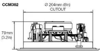
CCM3 Series speakers require ceiling aperture and height clearance dimensions described in the following table:
Minimum Height
Model Aperture Diameter Clearance
CCM362 204mm (8.0 in) 79mm (3.2 in)
CCM382 253mm (9.9 in) 85mm (3.4 in)
Note: If CCM3 Series speakers are to be installed in "new build" projects, pre-mount kits and back boxes are available. Use of pre-mount kits is described in Section 5. Use of back-boxes is described in the separate CI300 Back-box Installation document.
Before installing CCM3 Series speakers you should ensure that the ceiling locations chosen are free of obstructions such as pipe work, ducting or wiring that will interfere with the installation. In existing dry-wall construction, use a stud-finding tool to help you map the ceiling construction and a pipe detector to scan the proposed installation locations.
text_image
CCM362 Ø 204mm (8in) CUTOUT 79mm (3.2in)
text_image
CCM382 Ø 253mm (9.9in) CUTOUT 85mm (3.4in)Diagram 1
Aperture and height clearance
3. Positioning CCM3 Series Speakers
The appropriate position for CCM3 Series speakers within the listening environment will depend on their specific application:
General Background Audio Applications:
For applications where single CCM3 Series speakers are required to operate independently to provide background audio, they can be located substantially as installation convenience and architecture dictate. The only acoustic constraint to bear in mind is that corner locations will result in significantly emphasised low frequencies and should be avoided.
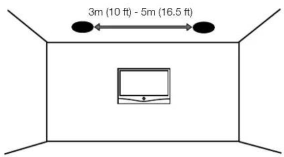
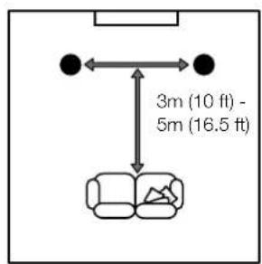
Stereo Audio Applications:
For applications where a pair of CCM3 Series speakers is to be used for conventional stereo reproduction, they should be located between 3m (10 ft) and 5m (16.5ft) apart and a similar distance in front of the listening area. Try to avoid corner locations for the speakers and to ensure that acoustic environment around each speaker is similar.
Note: Different acoustic environments might be, for example, a bare wall and a heavily curtained window.
Multi-channel Audio Applications:
For applications where multiple CCM3 Series speakers are to be used for multi-channel audio-visual systems, the front and centre speakers should be located approximately 0.5m (20 in) in front of the plane of the screen. The centre speaker should be on the centre line of the screen and the front speakers each laterally within approximately 0.5m (20 in) of the sides of the screen. Surround channel CCM3 Series speakers should be located just behind and either side of the listening position. Try to avoid corner locations for any of the speakers and to ensure that the acoustic environment around each front and surround speaker is similar.
Stereo Audio Applications
text_image
3m (10 ft) - 5m (16.5 ft)Multi-channel Audio Applications

text_image
0.5m (20in) 0.5m (20in)Diagram 2
Positioning
Note: Different acoustic environments might be, for example, a bare wall and a heavily curtained window.
Diagram 2 illustrates the general speaker location guidelines.
Note: The nature of the installation of ceiling speakers means that it is sometimes impractical to locate them in the acoustically ideal positions. In these cases they should be located as close as is practical to the ideal positions. Your local Bowers & Wilkins retailer will be able to offer advice if required.
Note: CCM3 Series drive units create stray magnetic fields. We recommend that magnetically sensitive items such as CRT screens and magnetic cards for example, are kept at least 0.5m (20 in) from the speaker. LCD and plasma screens are not affected by magnetic fields.
text_image
3m (10 ft) - 5m (16.5 ft)
text_image
0.5m (20in)4. Installing CCM3 Series Speakers
To install a CCM3 Series speaker proceed as described in the following paragraphs:
4.1 Using the supplied aperture template, mark a cut line on the ceiling. Check the cut line defines the correct aperture diameter. Cut along the line with an appropriate tool to create a round aperture in the ceiling.
Note: Ensure that there is enough free space internally adjacent to the aperture for the dog clamps.
Note: To reduce the possibility of the ceiling buzzing or rattling, adhesive mastic can be applied between the studs and sheetrock in the vicinity of the speaker aperture.
4.2 If speaker cable is already present in the ceiling space, pull the cable down through the aperture. If speaker cables are not already installed this should be done at this stage. It is likely that you will need to gain access through the floor above to route the cables through the ceiling space.
Leave enough spare cable through the aperture to ease connection to the speaker, but not so much that it is likely to buzz or rattle when pushed back up into the ceiling space. Approximately 1.0m (3 ft) is appropriate.
Note: Always use high quality, low resistance speaker cable. Low resistance is especially important if the length of cable from amplifier to speaker exceeds 5m. Your local Bowers & Wilkins retailer will be able to offer advice on speaker cable selection if required.
4.3 Now connect the speaker cable to the spring terminals on the side of the baffle. Ensure that the speaker connection polarity is correct: the cable connected to the positive terminal on the amplifier should be connected to the red spring terminal on the frame. Similarly, the cable connected to the negative terminal on the amplifier should be connected to the black spring terminal on the frame. Diagram 3 illustrates cable connection.
Note: If an amplifier is already connected to the cable it should be switched off while connections are being made to the back box.
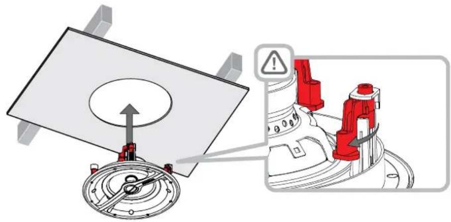
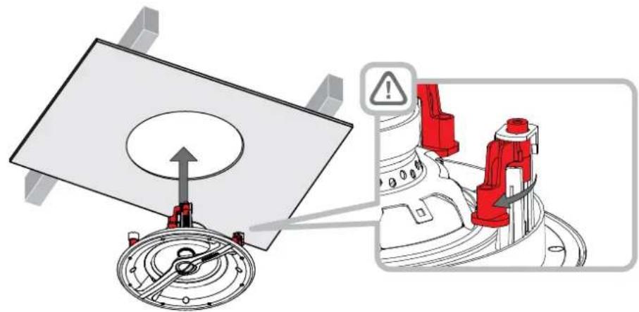
4.4 With the speaker connected to the cable it can be inserted into the ceiling aperture. Ensure that the four dog clamps are rotated inwards so that they can pass through the aperture, then lift the speaker up so that the flange is flush on the ceiling. Take care that the connection cable does not become trapped anywhere.
To secure the speaker user a Phillips screwdriver inserted through the dog-clamp access holes in the front of the speaker. Take great care that not to damage the speaker drive units with the screwdriver. Engage the screwdriver with each dog-clamp screw in turn and tighten them. Diagram 4 illustrates inserting and securing the speaker.
Note: If the ceiling is to be painted after the speakers have been installed, the supplied paint mask should be used.
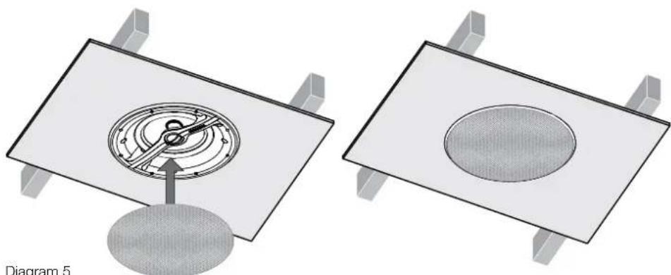
4.5 The grille can now be fitted. The grille is held in place magnetically so simply needs to be aligned with the groove in the frame flange where it will click into place. Diagram 5 illustrates fitting the grille.
The CCM3 Series speaker is now installed and ready for use.

text_image
Technical diagram of a mechanical assembly with labeled parts and directional arrows indicating motion or movement.Diagram 3 Cable connection
natural_image
Technical diagram showing a mechanical assembly with a rotating component and a warning symbol (no text or labels present)
text_image
Diagram 4 Inserting and securing the speakerDiagram 4 Inserting and securing the speaker
natural_image
Diagram showing two 3D mechanical components with internal circular features, one with a pointer and the other a circular opening (no text or symbols)Diagram 5 Fitting the grille
5 Using a Pre-mount Kit
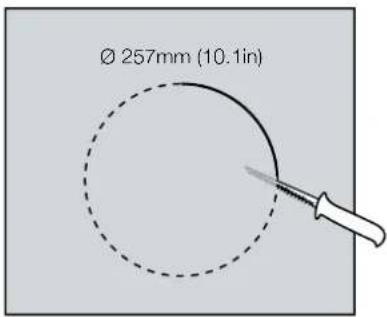
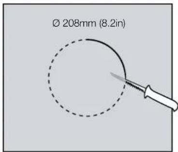
Custom install pre-mount kits enable the locations of in-ceiling and in-wall speakers to be defined before the sheetrock (plasterboard) is fitted to the studs (joists). Routing and cutting of speaker cable is also made easier using pre-mount kits. A pre-mount kit (PMK) comprises a plastic moulding that defines the aperture size of the specific speaker model, two perforated metal straps and four plastic clips.
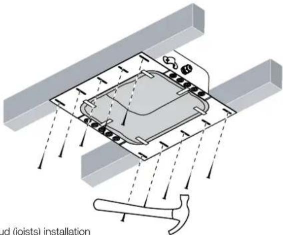
To use a PMK, first attach one strap to each side of the moulding using the plastic clips. The PMK assembly can now be attached to the studwork by nailing the metal straps to the studs so that the plastic moulding is located at the appropriate position.
When the sheetrock (plasterboard) is subsequently fitted (marked on the outside to denote the position of the pre-mount kit) the PMK plastic moulding serves as an internal cut guide that significantly cases cutting the speaker aperture.
Diagrams 6 to 9 illustrate the PMK installation.
PMK C8
text_image
Ø 257mm (10.1in)PMK C6
text_image
Ø 208mm (8.2in)Diagram 8
PMK cutout dimensions

text_image
Diagram 6 PMK strap attachment
text_image
am 7 stud (joists) installationDiagram 7
PMK stud (joists) installation

text_image
um 9 rock (plasterboard) Installation6 Using a Back-box Kit
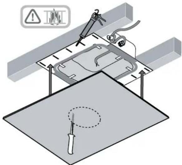
Custom install back-box kits comprise a fire-proof box that can be fitted behind in-wall or ceiling speakers before the sheetrock (plasterboard) is fitted to the studs (joists). As well as enabling compliance with fire regulations, back-boxes also help optimise speaker performance by providing a defined acoustic loading volume. A minimum clearance depth of 140mm from the outer stud (joist) plane to any rear obstruction is required to fit a back-box.
Back-boxes incorporate holed side flanges that are intended to be nailed to adjoining studs (joists). All the nail holes should be used to help minimise the risk of the flange vibrating against the stud (joist) when the speaker is in use.
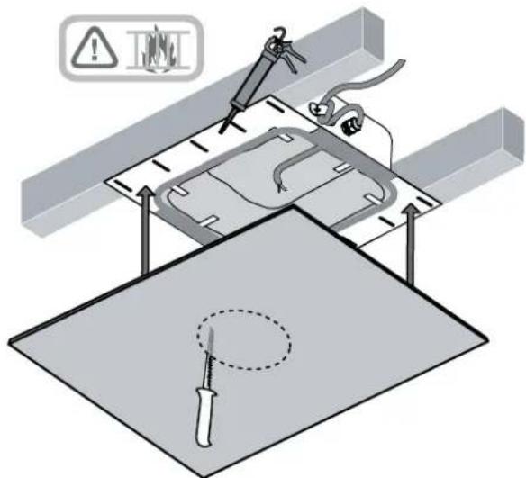
Speaker cable is bought into back-boxes via sealing glands. Once the cable has been brought through the gland, and the gland tightened, fire-retardant sealing mastic should be used to seal the assembly. Ensure that a generous length of cable is available in the back-box before the gland is sealed. A cable clamp adjacent to the gland provides cable strain relief.
When the sheetrock (plasterboard) is fitted over the back box a generous bead of fire-retardant sealing mastic should be applied to the back box flanges in order to seal the assembly and minimise the possibility of vibration when the speaker is in use.
Diagrams 10 to 12 illustrate back-box installation.
text_image
Cloud (joists) installationDiagram 10
Back-box stud (joists) installation

text_image
Technical diagram showing installation of a mechanical component with labeled parts and warning symbolsDiagram 11
Cable installation

text_image
Technical diagram showing a mechanical assembly with warning symbols and a tool, including a magnified view of a component with a screwdriver.Diagram 12
Sheetrock (plasterboard) Installation
text_image
Bowes & Wiking Home Audio Aged out videowww.bowers-wilkins.com
1. Déballage
text_image
Technical diagram of a mechanical assembly with labeled parts and directional arrows indicating motion or movement.natural_image
Technical diagram showing a mechanical assembly with a rotating component and a warning symbol (no text or labels present)
natural_image
Two 3D diagrams showing mechanical components inside rectangular frames, one with a central gear-like feature and the other a circular opening (no text or symbols)text_image
Technical diagram showing cable installation and safety warning icons with labelstext_image
Technical diagram showing a soldering or welding process with warning symbols and a tool, including a magnified view of the component.text_image
Technical diagram of a mechanical assembly with labeled parts and directional arrows indicating motion or movement.natural_image
Technical diagram showing a mechanical assembly with a rotating component and a warning symbol (no text or labels present)
natural_image
Two 3D mechanical components with internal circular features, one with a pointer and the other a circular opening (no text or symbols)text_image
Technical diagram showing installation of a mechanical component with labeled parts and warning symbolsAbbildung 11
Installation des Kabels

text_image
Technical diagram showing a welding or cutting process with labeled warning symbols and a tool on a workbench.CCM362 204mm (8.0 in) 79mm (3.2 in)
CCM382 253mm (9.9 in) 85mm (3.4 in)
text_image
CCM362 Ø 204mm (8in) CUTOUT 79mm (3.2in)
text_image
CCM382 Ø 253mm (9.9in) CUTOUT 85mm (3.4in)text_image
3m (10 ft) - 5m (16.5 ft)
text_image
3m (10 ft) - 5m (16.5 ft)text_image
0.5m (20in) 0.5m (20in)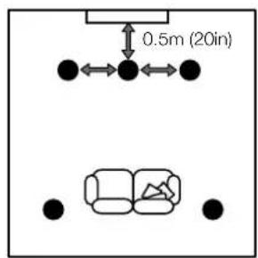
text_image
0.5m (20in)text_image
Technical diagram of a mechanical assembly with labeled parts and directional arrows indicating motion or movement.text_image
Technical diagram showing a mechanical assembly with a rotating component and warning symbol indicating hazard.
text_image
Diagrama 4 Segurando a colunaDiagrama 4 Segurando a coluna

natural_image
Diagram showing two 3D mechanical components with internal circular features, one with a pointer and the other a circular opening (no text or symbols)text_image
Ø 257mm (10.1in)PMK C6

text_image
Ø 208mm (8.2in)text_image
Diagrama 6 Fixando as faixas do PMK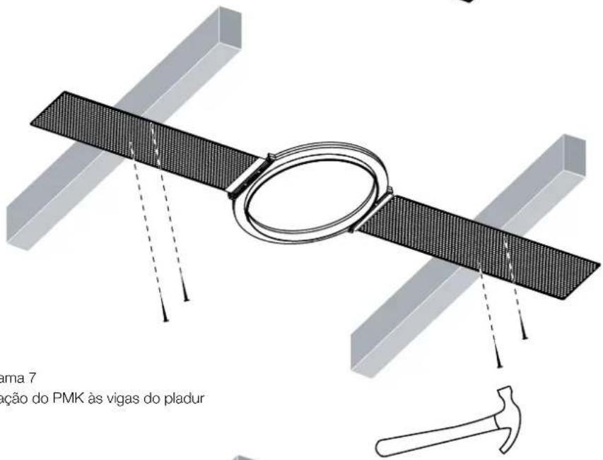
text_image
Technical diagram showing cable installation and safety warning icons with labelstext_image
Technical diagram showing a mechanical assembly with warning symbols and a tool, including a magnified view of a screwdriver on a workbench.text_image
Bowling & Wiking Home Audio Aged out videowww.bowers-wilkins.com
text_image
Technical diagram of a mechanical assembly with labeled parts and directional arrows indicating motion or movement.text_image
Technical diagram showing a mechanical assembly with labeled components and warning symbol
natural_image
Two 3D mechanical components with circular features, one with a pointer and the other a circular opening (no text or symbols)text_image
Technical diagram showing cable installation with warning symbols and component labelsFigura 11
Fissaggio del cavo
text_image
Technical diagram showing a mechanical assembly with warning symbols and a tool, including a magnified view of a component with a screwdriver.Figura 12
Posa in opera del pannello in cartongesso
text_image
Bowling & Wiking Home Audio Aged in videowww.bowers-wilkins.com
1. Uitpakken
text_image
Technical diagram of a mechanical assembly with labeled parts and directional arrows indicating motion or movement.text_image
Technical diagram showing mechanical assembly with labeled components and warning symbol
natural_image
Two 3D mechanical components with internal circular features, one labeled 'Afbeelding 5' (no other text or symbols)text_image
Ø 257 mm (10,1")PMK C6

text_image
Ø 208 mm (8,2")Afbeelding 8
text_image
Technical diagram showing cable installation with warning symbols and component labelsAfbeelding 11
Kabelbevestiging

text_image
Technical diagram showing a soldering or welding process with warning symbols and a tool, including a magnified view of the component.text_image
Bowers & Writing BOWERS & Writing BOWERS & Writing BOWERS & Writing BOWERS & Writing
text_image
Bowling & Wiking Home Audio Aged in videowww.bowers-wilkins.com
1. Распаковка
text_image
3 M (10 ft) - 5 M (16.5 ft)
text_image
3 M (10 ft) - 5 M (16.5 ft)text_image
0.5 M (20 in)text_image
Technical diagram of a mechanical assembly with labeled parts and directional arrows indicating motion or movement.text_image
Technical diagram showing a mechanical assembly with labeled components and warning symbol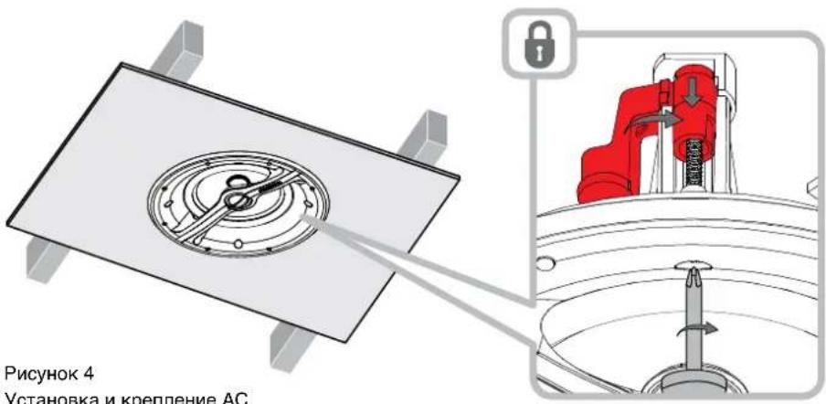
natural_image
Two 3D mechanical components with internal circular features, one with a pointer and the other a circular opening (no text or symbols)text_image
Technical diagram showing cable installation with warning symbols and component labelsРисунок 11
Прокладка кабеля

text_image
Technical diagram showing a mechanical assembly with warning symbols and a screwdriver, likely illustrating a repair or installation procedure.text_image
Bowling & Wiking Home Audio Aged in videowww.bowers-wilkins.com
1. Vybalení
CCM362 204mm (8.0 in) 79mm (3.2 in)
CCM382 253mm (9.9 in) 85mm (3.4 in)
text_image
Technical diagram of a mechanical assembly with labeled parts and directional arrows indicating motion or movement.text_image
Technical diagram showing a mechanical assembly with labeled components and warning symbol
natural_image
Two 3D mechanical components with internal circular features, one with a pointer and the other a circular opening (no text or symbols)text_image
Ø 257mm (10.1 in)PMK C6

text_image
Ø 208mm (8.2 in)Obrázek 8
text_image
Technical diagram showing cable installation with warning symbols and component labelsObrázek 11
Instalace kabelu

text_image
Technical diagram showing a soldering or welding process with warning symbols and a tool, including a magnified view of the component.text_image
Bowling & Wiking Home Audio Aged in videowww.bowers-wilkins.com
1. Kicsomagolás
CCM362 204mm (8.0 in) 79mm (3.2 in)
CCM382 253mm (9.9 in) 85mm (3.4 in)
text_image
CCM362 Ø 204mm (8in) CUTOUT 79mm (3.2in)
text_image
CCM382 Ø 253mm (9.9in) CUTOUT 85mm (3.4in)- ábra
Kivágási méretek
text_image
3m (10 ft) - 5m (16.5 ft)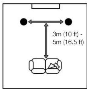
text_image
3m (10 ft) - 5m (16.5 ft)text_image
0.5m (20in) 0.5m (20in)
text_image
0.5m (20in)- ábra
Elhelyezés
text_image
Technical diagram of a mechanical assembly with labeled parts and directional arrows indicating motion or movement.text_image
Technical diagram showing a mechanical assembly with labeled components and warning symbol
natural_image
Two 3D mechanical components with internal circular features, one with a central knob and the other a circular opening (no text or symbols)text_image
Ø 257mm (10.1in)PMK C6

text_image
Ø 208mm (8.2in)- ábra
natural_image
3D diagram of a satellite with antenna and base plate, no text or symbols presenttext_image
Technical diagram showing cable installation and safety warning icons on a device panel with labeled components- ábra
Kábel installáció
text_image
Technical diagram showing a soldering or welding process with warning symbols and a tool, including a magnified view of the component.text_image
Technical diagram of a mechanical assembly with labeled parts and directional arrows indicating motion or movement.text_image
Technical diagram showing a mechanical assembly with labeled components and warning symbol
natural_image
Two 3D mechanical assembly diagrams showing a circular component being inserted into a plate, with no visible text or symbols.text_image
ie back-boxatext_image
Technical diagram showing cable installation with warning symbols and component labelsRysunek 11
text_image
Technical diagram showing a soldering or welding process with warning symbols and a tool, including a magnified view of the component.text_image
Technical diagram of a mechanical assembly with labeled parts and directional arrows indicating motion or movement.图3
接线连接
text_image
Technical diagram showing a mechanical assembly with labeled components and warning symbol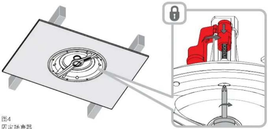
text_image
图4 固定扬声器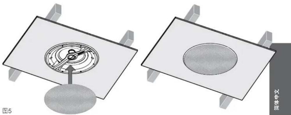
natural_image
Two 3D mechanical assembly diagrams showing internal components and a central circular feature, no text or symbols present.安装面网
5 使用预装件
text_image
Technical diagram showing cable installation and safety warning icons on a panel, with labeled components and connection details.图11 接线安装

text_image
Technical diagram showing a soldering or welding process with warning symbols and a tool, including a magnified view of the component.图12 石膏板(石膏灰泥板)安装
text_image
Bowling & Wiking Home Audio Aged out videowww.bowers-wilkins.com
1. 開梱
text_image
Technical diagram of a mechanical assembly with labeled parts and directional arrows indicating motion or movement.図3 ケーブルの接続
text_image
Technical diagram showing a mechanical assembly with labeled components and warning symbol
natural_image
Two 3D mechanical assembly diagrams showing internal components and a central circular feature, no text or symbols present.図5 グリルの取り付け
5 プレマウント・キットの使い方
text_image
Technical diagram showing cable installation with warning symbols and component labels図11 ケーブルの接続

text_image
Technical diagram showing a soldering or welding process with warning symbols and a tool, including a magnified view of the component.図12 石膏ボードの取り付け