
KOS-L432 - Television KENWOOD - Free user manual and instructions
Find the device manual for free KOS-L432 KENWOOD in PDF.
| Product Type | Vehicle LCD Monitor |
| Brand | KENWOOD |
| Model | KOS-L432 |
| Screen Size | 4.3 inches (diagonal) |
| Display Type | Active Matrix TFT LCD, LED Backlight |
| Resolution | 480 x 272 pixels (RGB) |
| Effective Pixels | 99.99% |
| Video Input Color System | NTSC / PAL |
| Analog RGB Input | 0.7 Vp-p / 75 Ω |
| Power Supply | 14.4 V DC (11 - 16 V) |
| Power Consumption | 250 mA |
| Operating Temperature | -10°C to +60°C |
| Storage Temperature | -20°C to +70°C |
| Dimensions (W x H x D) | 125 x 75 x 18.5 mm |
| Weight | 150 g |
| Chassis Material | Plastic |
| Cleaning | Soft, dry cloth (silicone), mild detergent if needed |
| Main Functions | Video display, KENWOOD A/V controller control (KOS-V500, KOS-V1000), reset button |
| Safety | Do not watch the screen while driving; professional installation recommended |
| Repairability | Replaceable fuse; contact an authorized dealer for parts |
| General Information | Class B digital device complying with Canadian ICES-003 |
| Supplied Accessories | Bracket, chassis, system cable, removal tool, paper template |
Frequently Asked Questions - KOS-L432 KENWOOD
User questions about KOS-L432 KENWOOD
0 question about this device. Answer the ones you know or ask your own.
Ask a new question about this device
Download the instructions for your Television in PDF format for free! Find your manual KOS-L432 - KENWOOD and take your electronic device back in hand. On this page are published all the documents necessary for the use of your device. KOS-L432 by KENWOOD.
USER MANUAL KOS-L432 KENWOOD
Take the time to read through this instruction manual.
Familiarity with installation and operation procedures will help you obtain the best performance from your new monitor.
For your records
Record the serial number, found on the back of the unit, in the spaces designated on the warranty card, and in the space provided below. Refer to the model and serial numbers whenever you call upon your Kenwood dealer for information or service on the product. Model KOS-L432 Serial number
US Residence Only
Register Online
Register your Kenwood product at
www.Kenwoodusa.com
WARNING
To prevent injury or fire, take the following precautions:
- Do not watch or fix your eyes on the unit's display when you are driving for any extended period.
CAUTION
To prevent damage to the machine, take the following precautions:
- You cannot view video pictures whilst the vehicle is moving. To enjoy video pictures, find a safe place to park and engage the parking brake.
- If you experience problems during installation, consult your Kenwood dealer.
- When you purchase optional accessories, check with your Kenwood dealer to make sure that they work with your model and in your area.
- If the unit fails to operate properly, press the Reset button.
Reset button
- The illustrations of the display and the panel appearing in this manual are examples used to explain more clearly how the controls are used. Therefore, what appears on the display in the illustrations may differ from what appears on the display on the actual equipment, and some of the illustrations on the display may represent something impossible in actual operation.
Cleaning the Unit
If the faceplate of this unit is stained, wipe it with a dry soft cloth such as a silicon cloth.
If the faceplate is stained badly, wipe the stain off with a cloth moistened with neutral cleaner, then wipe it again with a clean soft dry cloth.

- Applying spray cleaner directly to the unit may affect its mechanical parts. Wiping the faceplate with a hard cloth or using a volatile liquid such as thinner or alcohol may scratch the surface or erases characters.
Screen brightness during low temperatures
When the temperature of the unit falls such as during winter, the liquid crystal panel's screen will become darker than usual. Normal brightness will return after using the monitor for a while.
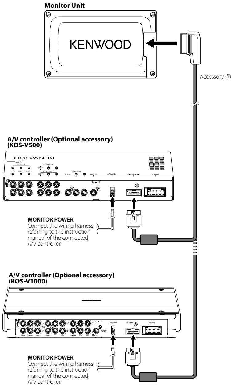
A/V controller you can control from the KOS-L432 (As of December, 2007):
KOS-V500, KOS-V1000
Information on Disposal of Old Electrical and Electronic Equipment (applicable for EU countries that have adopted separate waste collection systems)

Products with the symbol (crossed-out wheeled bin) cannot be disposed as household waste.
Old electrical and electronic equipment should be recycled at a facility capable of handling these items and their waste byproducts. Contact your local authority for details in locating a recycle facility nearest to you. Proper recycling and waste disposal will help conserve resources whilst preventing detrimental effects on our health and the environment.
CE
Declaration of Conformity with regard to the EMC Directive 2004/108/EC
Manufacturer:
Kenwood Corporation
2967-3 Ishikawa-machi, Hachioji-shi, Tokyo, 192-8525 Japan
EU Representative's:
Kenwood Electronics Europe BV
Amsterdamseweg 37, 1422 AC UITHOORN, The Netherlands
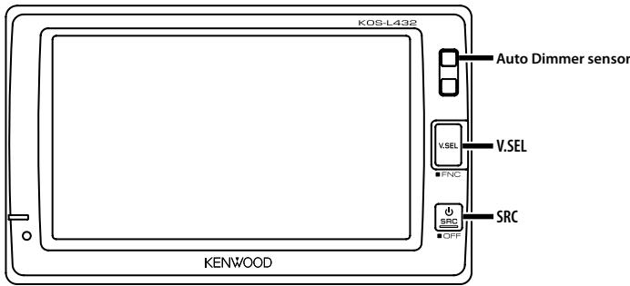

Controlling of optional A/V controllers is possible by touching the screen of this unit.
Functions which can be controlled vary depending on the A/V controllers. Refer to the instruction manual of the connected A/V controller for more information.
Power
Turning ON the Power
Press the [SRC] button.
Turning OFF the Power
Press the [SRC] button for at least 1 second.
Switches the audio source
Press the [SRC] button.
Each time the button is pressed, the audio source is changed.
![KENWOOD KOS-L432 - Press the [SRC] button. - 1](/content/2020/05/124398/images/1b3139a37ba80556344d8914172da377a466c526b2945f3ae2181e4ac55aa4c6.jpg)
Refer to
Switches the video source
Press the [V.SEL] button.
Each time the button is pressed, the video source is changed.
![KENWOOD KOS-L432 - Press the [V.SEL] button. - 1](/content/2020/05/124398/images/a3c70da143f0e4ed9bb2e88c3c543ca0ce2826135ba108e22340a5a34ba8538f.jpg)
Refer to
Switches the function screen
Switches to the control screens such as Source Control Screen.
Press the [V.SEL] button for at least 1 second.
Each time the button is pressed for at least 1 second, the function control screen is changed.
Setting
Picture & Easy Control Panel
Source Control Screen
Picture Panel (OFF)

Refer to
①
②
(3)
4

(5)
- To prevent short circuits, remove the key from the ignition and disconnect the terminal of the battery.
- Make the proper input and output cable connections for each unit.
- Connect the wiring harness connector to the unit.
- Install the unit in your car.
- Reconnect the terminal of the battery.
- Press the reset button. (page 2)
WARNING
- To prevent shorting, disconnect the battery cable from the negative terminal of the battery during installation.
- Be sure to firmly stabilise this product. Do not install it in a location which is not stable.
- Follow the installation and wiring procedures described in this manual. Improper wiring or modified installation can not only result in malfunction or damage to the unit but may also result in an accident.
-
Do not install the unit in the following locations.
-
A location which interferes with the operation of the air bag system.
- A location which is not made of plastic.
→ Installing on leather, wood or cloth may damage the surface.
-
A location subject to direct sunlight, subject to the air from the air conditioner, or subject to moisture or high temperature.
This may cause deformation of the monitor unit. -
If you are not going to install the unit using the supplied monitor stand, be sure to use a commercially available monitor stand. (Mounting holes for such a stand are located on the bottom of the monitor unit.)
!
- Mounting and wiring this product requires skills and experience. For safety's sake, leave the mounting and wiring work to professionals.
- Do not install the unit in a spot exposed to direct sunlight or excessive heat or humidity. Also avoid places with too much dust or the possibility of water splashing.
- Do not use your own screws. Use only the screws provided. If you use the wrong screws, you could damage the unit.
- If the fuse blows, first make sure that the wires have not caused a short circuit, then replace the old fuse with one with the same rating.
- Do not let unconnected wires or terminals touch metal on the car or anything else conducting electricity. To prevent short circuits do not remove the caps from unused terminals or from the ends of the unconnected wires.
- After the unit is installed, check whether the brake lamps, blinkers, wipers, etc. on the car are working properly.
- Insulate unconnected wires with vinyl tape or other similar material.
- Thoroughly wipe away oil and other dirt from the installation surface. Please avoid installation on uneven surfaces.
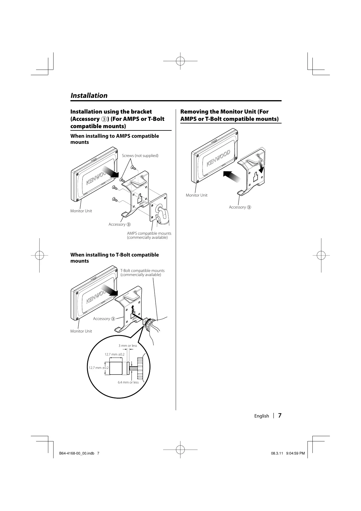
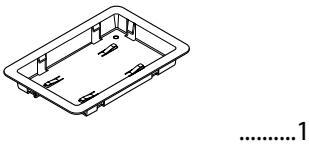
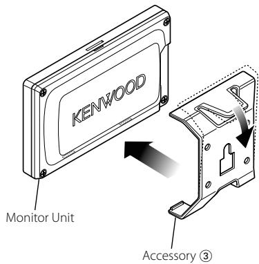
Installation using the bracket (Accessory ③) (For AMPS or T-Bolt compatible mounts)

When installing to AMPS compatible mounts
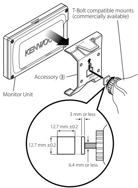
When installing to T-Bolt compatible mounts
Removing the Monitor Unit (For AMPS or T-Bolt compatible mounts)
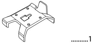
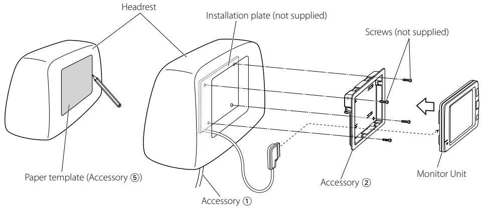
Installation using the frame (Accessory ②) (For Headrest)
Mounting and wiring this product requires skills and experience. For safety's sake, leave the mounting and wiring work to professionals.
Before mounting the monitor to the headrest:
- Perform the required external connections first (Accessory ①).
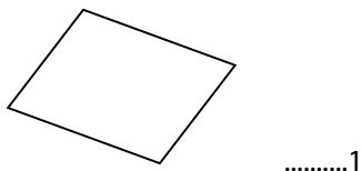
- Using the supplied paper template (Accessory ⑤), mark the area to be cut out of the headrest, then carefully cut it.
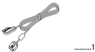
1 Connect Monitor and system cable (Accessory ①).
2 Install the monitor unit in the frame (Accessory ②).
Removing the Monitor Unit (For Headrest)
1 Insert the removal tool (Accessory ④) deeply into the slots on each side, as shown.
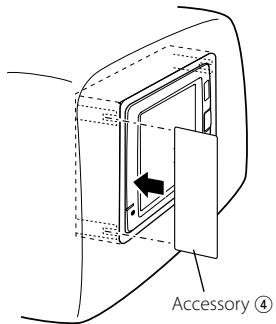
2 Pull the monitor unit all the way out with your hands, being careful not to drop it.
What might seem to be a malfunction in your unit may just be the result of slight misoperation or miswiring. Before calling service, first check the following table for possible problems.
? The power does not turn ON.
- The monitor is not attached to the bracket securely.
Attach the motor to the bracket until it clicks.
? Nothing happens when the buttons are pressed.
- The computer chip in the unit is not functioning normally.
Press the reset button on the unit (page 2).

Refer to the instruction manual of the connected A/V controller for troubleshooting on the operation.
Specifications
Specifications subject to change without notice.
Monitor Section
Screen size
: 4.3 inches wide
95.0 (W) × 53.9 (H) mm
3-6/8 (W) × 2-1/8 (H) inches
Display system
: Transmissive with Micro Reflective type, VA mode LCD panel
Drive system
: TFT active matrix system
Number of pixels
: 391,680 pixels (480 H × 272 V × RGB)
Effective pixels
:99.99%
Pixel arrangement
: RGB striped arrangement
Back lighting
:LED
Video section
Color System of External Video Input
: NTSC/ PAL
Analog RGB input
: 0.7 Vp-p/ 75 Ω
General
Operating voltage
: 14.4 V DC (11 - 16 V)
Current consumption
: 250 mA
Operational temperature range
: -10 °C to +60 °C
Storage temperature range
: -20 °C to +70 °C
Dimensions (W× H× D)
: 125× 75× 18.5mm
4-15/16 × 2-15/16 × 6/8 inch
Weight
: 150 g (0.33 lbs)
Although the effective pixels for the liquid crystal panel is given as 99.99% or more, 0.01% of pixels may not light or may light incorrectly.
AVERTISSEMENT
95,0 (L) × 53,9 (H) mm
3-6/8 (L) × 2 - 1 / 8 (H) pouces
Système d'affichage
:14.4V DC (11V - 16V)
消费电流
:250mA
工作环境温度范围
:-10°C至+60°C
保存环境温度范围
:-20°C至 +70°C
外形尺寸 (W× H× D)
: 125 × 75 × 18.5 mm
4-15/16 × 2-15/16 × 6/8 英寸
重量
:150g(0.33磅)
This equipment may generate or use radio frequency energy. Changes or modifications to this equipment may cause harmful interference unless the modifications are expressly approved in the instruction manual. The user could lose the authority to operate this equipment if an unauthorized change or modification is made.
NOTE
This equipment has been tested and found to comply with the limits for a Class B digital device, pursuant to Part 15 of the FCC Rules. These limits are designed to provide reasonable protection against harmful interference in a residential installation. This equipment may cause harmful interference to radio communications, if it is not installed and used in accordance with the instructions. However, there is no guarantee that interference will not occur in a particular installation. If this equipment does cause harmful interference to radio or television reception, which can be determined by turning the equipment off and on, the user is encouraged to try to correct the interference by one or more of the following measures:
Reorient or relocate the receiving antenna.
- Increase the separation between the equipment and receiver.
- Connect the equipment into an outlet on a circuit different from that to which the receiver is connected.
- Consult the dealer or an experienced radio/TV technician for help.
This device complies with part 15 of the FCC Rules. Operation is subject to the following two conditions:
(1) This device may not cause harmful interference, and
(2) this device must accept any interference received, including interference that may cause undesired operation.
NOTE
This Class B digital apparatus complies with Canadian ICES-003.
REMARQUE
- WARNING
- To prevent injury or fire, take the following precautions:
- CAUTION
- To prevent damage to the machine, take the following precautions:
- Cleaning the Unit
- Screen brightness during low temperatures
- A/V controller you can control from the KOS-L432 (As of December, 2007):
- Information on Disposal of Old Electrical and Electronic Equipment (applicable for EU countries that have adopted separate waste collection systems)
- CE
- Declaration of Conformity with regard to the EMC Directive 2004/108/EC
- Manufacturer:
- EU Representative's:
- Power
- Switches the audio source
- Press the [SRC] button.
- Switches the video source
- Press the [V.SEL] button.
- Switches the function screen
- Press the [V.SEL] button for at least 1 second.
- Setting
- !
- Installation using the bracket (Accessory ③) (For AMPS or T-Bolt compatible mounts)
- Removing the Monitor Unit (For AMPS or T-Bolt compatible mounts)
- Installation using the frame (Accessory ②) (For Headrest)
- Before mounting the monitor to the headrest:
- Removing the Monitor Unit (For Headrest)
- ? The power does not turn ON.
- ? Nothing happens when the buttons are pressed.
- Specifications
- Monitor Section
- Video section
- General
- AVERTISSEMENT
- NOTE
- REMARQUE
Brand : KENWOOD
Model : KOS-L432
Category : Television