VC 35 L MC Flex - Vacuum Cleaner KARCHER - Free user manual and instructions
Find the device manual for free VC 35 L MC Flex KARCHER in PDF.

User questions about VC 35 L MC Flex KARCHER
0 question about this device. Answer the ones you know or ask your own.
Ask a new question about this device
Download the instructions for your Vacuum Cleaner in PDF format for free! Find your manual VC 35 L MC Flex - KARCHER and take your electronic device back in hand. On this page are published all the documents necessary for the use of your device. VC 35 L MC Flex by KARCHER.
USER MANUAL VC 35 L MC Flex KARCHER
natural_image
Line drawing of a vacuum cleaner with attached hose and filter (no text or symbols)Deutsch 6
English 14
Français 22
Italiano 31
Nederlands 40
Español 48
Português 57
Dansk 65
Norsk 73
Svenska 81
Suomi 89
Ελληνικά 97
Türkçe 107
Русский 115
Magyar 125
Čeština 133
Slovenščina 141
Polski 149
Românește 158
Slovenčina 166
Hrvatski 174
Srpski 182
Български 190
Eesti 199
Latviešu 207
Lietuviškai 215
Українська 223
natural_image
Geometric diagram showing a right-angled triangle with a shaded interior (no text or symbols)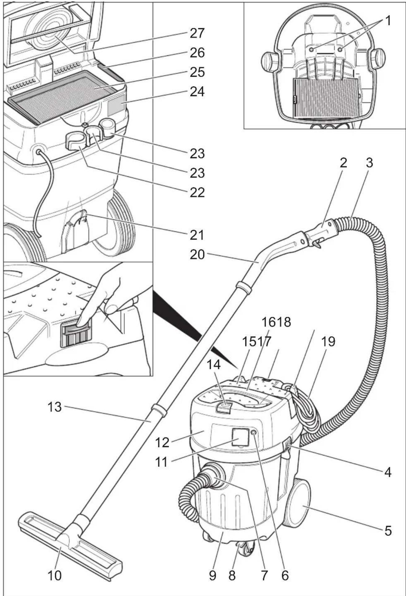
text_image
Technical diagram of a vacuum cleaner with numbered parts and exploded view, including handlebars, casing, and control panel.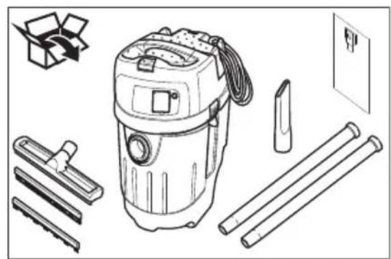
natural_image
Line drawing of a vacuum cleaner with various components including a box, paper clips, and tubes (no text or symbols)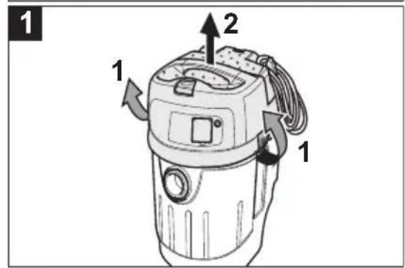
text_image
1 2 1 1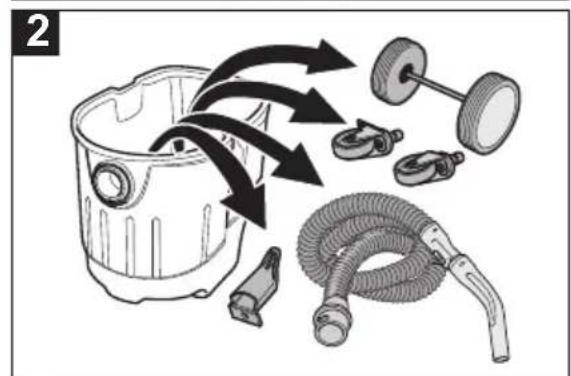
natural_image
Illustration of a mechanical component with arrows indicating flow or movement, including a cylindrical housing and hoses (no text or symbols)
text_image
3 2 1 "Click" "Click"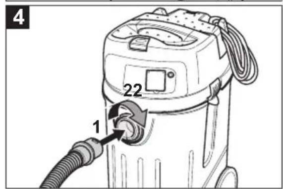
text_image
4 22 1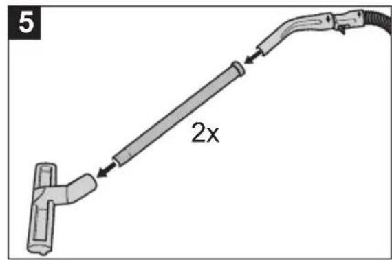
text_image
5 2x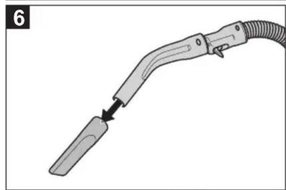
natural_image
Diagram of a handheld electric shock absorber with a curved tube and cable, showing a disassembly or insertion process (no text or symbols present)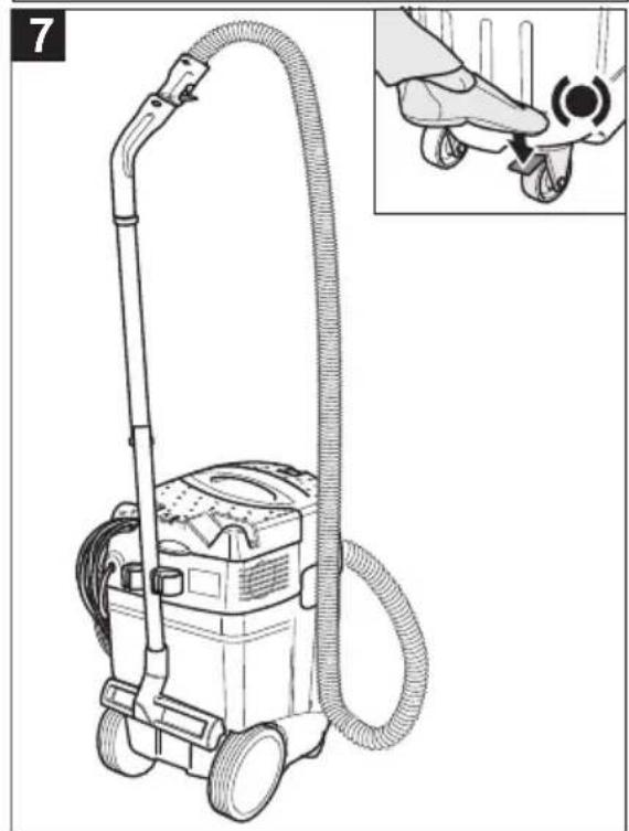
natural_image
Line drawing of a vacuum cleaner with hose and control panel, shown with an inset close-up of the hand adjusting its grip (no text or symbols present)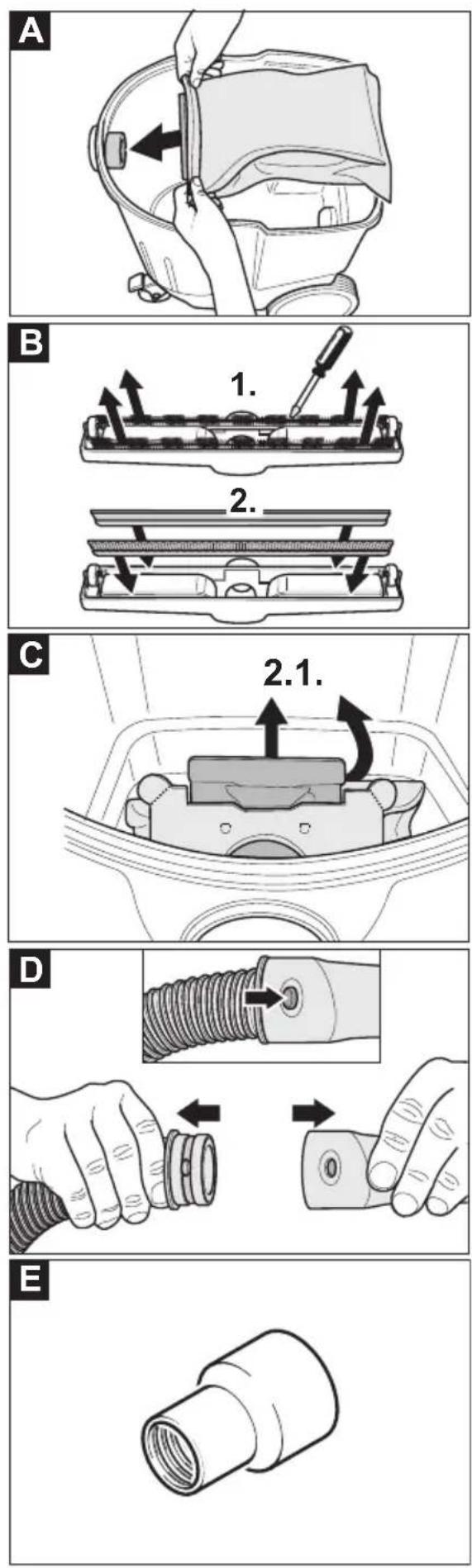
F

text_image
35 32 26 21,5 26,9 31 25 45G

natural_image
Diagram showing a welding torch being welded into two different types of connectors (no text or labels present)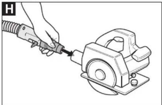
natural_image
Illustration of a hand using a tool to adjust or install a mechanical component (no text or symbols present)I
text_image
Press ① ②
Please read and comply with these original instructions prior to the initial
operation of your appliance and store them for later use or subsequent owners.
– Before first start-up it is definitely necessary to read the safety indications Nr. 5.956-249!
- The non-compliance of the operating and safety instructions may lead to damages of the appliance and to dangers for the operator and other persons.
– In case of transport damage inform vendor immediately
Contents
| Environmental protection EN - 1 | ||
| Symbols in the operating instructions | EN - 1 | |
| Proper use EN - 1 | ||
| Device elements EN - 2 | ||
| Symbols on the machine EN - 2 | ||
| Safety instructions EN - 2 | ||
| Start up EN - 2 | ||
| Operation EN - 4 | ||
| Transport EN - 4 | ||
| Storage EN - 5 | ||
| Maintenance and care EN - 5 | ||
| Troubleshooting EN - 6 | ||
| Disposal EN - 6 | ||
| Warranty | EN - 6 | |
| Accessories and Spare Parts EN - 7 | ||
| CE declaration | EN - 7 | |
| Technical specifications | EN - 8 | |
Environmental protection
 | The packaging material can be recycled. Please do not throw the packaging material into household waste; please send it for recycling. |
 | Old appliances contain valuable materials that can be recycled; these should be sent for recycling. Batteries, oil, and similar substances must not enter the environment. Please dispose of your old appliances using appropriate collection systems. |
Symbols in the operating instructions
⚠️Danger
Immediate danger that can cause severe injury or even death.
⚠ Warning
Possible hazardous situation that could lead to severe injury or even death.
Caution
Possible hazardous situation that could lead to mild injury to persons or damage to property.
Proper use
⚠ Warning
The appliance is suited for the extraction of dry, non-combustible, harmful dusts on machines and appliances; dust class L according to EN 60 335–2–69. Restriction: No carcinogenic substances may be vacuumed up.
- The machine is meant for dry and wet cleaning of floors and walls.
- This appliance is suited for the commercial use, e.g. in hotels, schools, hospitals, factories, shops, offices, and rental companies.
Device elements
1 Electrodes
2 Handle
3 Suction hose
4 Suction head lock
5 Impeller
6 Indicator lamp
7 Suction support
8 Steering roller
9 Dirt receptacle
10 Floor nozzle
11 Socket
12 Suction head
13 Suction pipe
14 Main switch
15 Filter cover
16 Carrying handle
17 Slide for filter cleaning
18 Cable hook
19 Power cord
20 Bender
21 Floor nozzle holder
22 Holder for floor nozzle
23 Holder for suction pipes
24 Nameplate
25 Flat fold filter
26 Exhaust filter
27 Filter dedusting
Symbols on the machine
WARNING: This appliance contains harmful dust. The emptying and maintenance, including the removal of the dust bag, may only be executed by trained personnel wearing suitable protection equipment. Do not switch on until the complete filter system has been installed.

Flat fold filter

Fleece filter bag
Note: The spare parts numbers are listed in the appendix.
Safety instructions
⚠ Warning
- When the outgoing air is carried back into the room, a sufficient ventilation rate L in the room must be ensured. To comply with the required limit values the carried back volume flow must be 50% of the fresh air volume flow (room volume V_R × ventilation rate L_W ) at maximum. Without a specific ventilation system the following applies: L_W = 1h^-1 .
- Only persons trained in the use of the machine and the handling of substances for which the machine is to be used including training in the safe disposal of the sucked-in material may use the machine.
- This appliance contains harmful dust. Evacuation and maintenance work, including the disposal of the dust collection containers, may only be performed by specialists who wear the appropriate protective equipment.
- Do not use the appliance without the complete filtering system.
- Please follow the safety regulations applicable to the materials that are to be treated.
Start up
The appliance allows 2 operating modes:
1 Industry vacuum cleaner mode (socket not used)
2 Dedusting mode (socket used)
→ Connect the suction hose and insert insert the suction nozzle or connect to the dust-generating device depending on the operating mode.
⚠ Warning
Do not vacuum without the filter elements; otherwise, the suction motor can get damaged and this can be hazardous to health
on account of increased release of fine dust particles.
Anti-static system
Static charge is deflected by providing earthing to the connection nozzles. This prevents the formation of sparks and current shocks with attachments with electrical conductivity included in the delivery.
Dry vacuum cleaning
- The appliance is equipped with a fleece bag with a locking slide, order no. 329.630 (5 pc).
Note: You can use this appliance to vacuum all types of dust up to dust class L. It is statutorily necessary to use a dust collection bag (see Filter systems for order number).
Note: The appliance is suited as industrial vacuum cleaner and as dedusting device for the mobile operation to take up dry, non-combustible dusts with MAK values greater than or equal to 1 mg/m ^3 .
Caution
The flat pleated filter must must always be in place while vacuuming.
- To vacuum fine dust, you must use an additional fleece filter bag.
Install fleece filter bag
Illustration A
→ Release and remove the suction head.
→ Insert the fleece filter bag.
→ Insert and lock the suction head.
Wet vacuum cleaning
⚠ Warning
No dusts hazardous to health should be sucked in during wet vacuuming.
Inserting the rubber lips
Illustration B
→ Remove the brush strips.
→ Install the rubber lips.
Note: The structured side of the rubber lips must point outwards.
Remove the fleece filter bag
Illustration C
→ Release and remove the suction head.
→ Pull the fleece filter bag towards the rear.
→ Pull the locking slide up and seal the fleece filter bag tightly when removing it.
→ Dispose of the fleece filter bag according to the local provisions.
→ Insert and lock the suction head.
- To suck wet dirt, first remove the fleece filter bag.
General
Caution
The flat pleated filter must must always be in place while vacuuming.
- If wet dirt is vacuumed with the upholstery or crevice nozzle or if water is sucked up from a container it is recommended to deactivate the "Filter Dedusting" function.
- If the maximum liquid level is reached the appliance will turn off automatically.
- In case of non-conductive liquids (such as emulsion drilling fluids, oils, and greases) the appliance is not turned off when the container is full. The filling level must be continuously monitored and the container must be emptied in time.
- After the wet vacuuming: Clean the flat folded filter with the filter cleaning. Clean the electrodes with a brush. Clean the container with a damp rag and dry it.
Clip connection
Illustration D
The suction hose is equipped with a clip system. All C-35/C-DN-35 accessories can be connected.
Operation
Turning on the Appliance
→ Plug in the main plug.
→ Switch on the appliance at the main switch.
Working with electrical power tools
⚠️Danger
Risk of injury and damage! The socket outlet is only for the connection of power tools to the vacuum cleaner. Any other use of the socket outlet is not permitted.
→ Connect the mains plug of the electric power tool to the vacuum cleaner.
→ Switch on the appliance at the main switch.
Indicator lamp is on; vacuum cleaner is in the standby mode.
Note: The vacuum cleaner is turned on and off automatically with the electric power tool.
Note: The vacuum cleaner starts automatically within 0.5 seconds and continues to run for 15 seconds after the power tool has being switched off.
Note: Please refer to "Technical specifications" for the power connection specifications of the power tools.
Illustration E
Illustration F
→ Use the appropriate connection socket or the universal connection socket and adapt it to the connector of the electric tool.
Illustration G
→ Remove the elbow from the suction hose.
→ Install the appropriate connection socket or universal connection socket on the suction hose.
Illustration H
→ Connect the adaptor to the electric power tool.
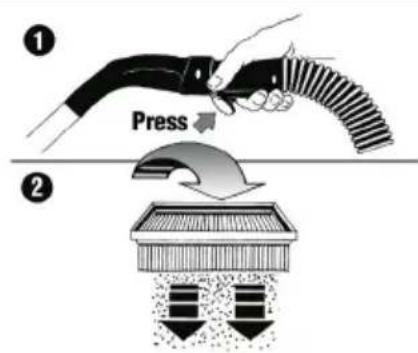
Filter dedusting
Note: A filter dedusting every 5 to 10 minutes will increase the life of the flat folded filter.
- Switch off filter dedusting:
→ Push the slide upward.
- Switch on filter dedusting:
→ Push the slide downward.
Illustration 1
→ Press and hold the switch on the handle for several seconds while the filter cleaning is turned on. The flat folded filter is automatically cleaned through an air jet (pulsating sound).
Turn off the appliance.
→ Filter dedusting: Repeatedly press the button on the handle while the filter cleaning is turned on.
→ Switch off the appliance at the main switch.
→ Pull out the mains plug.
After each operation
→ Empty the container.
→ Vacuum and wipe the appliance inside and outside with a damp cloth.
Storing the Appliance
→ Wind the mains cable around the cable holder.
→ Place the appliance in a dry room and secure it from unauthorized use.
Transport
Caution
Risk of injury and damage! Observe the weight of the appliance when you transport it.
→ Remove the suction pipe with the floor nozzle from the holder. Hold the appliance at the handle and at the suction pipe to transport it.
→ When transporting in vehicles, secure the appliance according to the guidelines from slipping and tipping over.
Storage
Caution
Risk of injury and damage! Note the weight of the appliance in case of storage.
This appliance must only be stored in interior rooms.
Maintenance and care
⚠️Danger
First pull out the plug from the mains before carrying out any tasks on the machine.
Dust extracting machines are safeguards for the prevention or elimination of hazards defined in the regulations of BGV A1.
- In order to carry out maintenance work, the user must disassemble, clean and service the unit, in so far as this is possible without endangering maintenance personnel and other persons. Suitable precautions include decontamination before the unit is disassembled. Precautions must be taken for local filtered forced air ventilation at the place where the unit is dissassembled, the cleaning of the maintenance surface and suitable protection of the personnel.
- The outside of the unit should be cleaned thoroughly and any harmful substances removed. Alternatively, a sealed coating may be applied before the unit is removed from the danger area. All unit parts are to be considered contaminated when they are removed from the danger area.
- In the framework of maintenance and repair work all contaminated objects that cannot be cleaned satisfactorily must be disposed of. Such objects must be disposed of in impermeable bags in accordance with the valid provisions for the disposal of such waste.
⚠ Warning
Safety equipment for preventing hazards must be serviced and maintained regularly. This means that the manufacturer's staff or persons trained by the manufacturer must check the equipment for proper functioning at least once a year, i.e. check for leaks, filter damage, functioning of the controlling elements, etc.
Caution
Risk of damage! Do not use detergents containing silicone to clean.
- No outside help is required for carrying out basic maintenance and cleaning.
- The appliance surface and the inside of the container should be cleaned regularly using a damp cloth.
⚠ Warning
Risk due to dust hazardous to health. Always use disposal clothing and P2 or higher breath-safe masks while carrying out maintenance tasks (such as changing filters).
Exchanging the flat pleated filter
→ Open filter door.
→ Take out the flat folded filter.
→ Dispose off the used flat-folded filter in a dust-tight bag according to the statutory provisions.
→ Remove the dirt that has accumulated on the pure air side.
→ Insert new flat-folded filter.
→ Close the filter door, it must lock into place.
Exchange the fleece filter bag
Illustration C
→ Release and remove the suction head.
→ Pull the fleece filter bag towards the rear.
→ Pull the locking slide up and seal the fleece filter bag tightly when removing it.
→ Dispose of the fleece filter bag according to the local provisions.
→ Insert the new fleece filter bag.
→ Insert and lock the suction head.
Replace the exhaust filter.
→ Open filter door.
→ Replace the exhaust filter.
→ Close the filter door, it must lock into place.
Cleaning the electrodes
→ Release and remove the suction head.
→ Clean the electrodes with a brush.
→ Insert and lock the suction head.
Troubleshooting
⚠️ Danger
First pull out the plug from the mains before carrying out any tasks on the machine.
Note: In case of a failure (e.g. filter breakage) the appliance must be turned off immediately. The failure must be remedied before the appliance is put into operation again.
Suction turbine does not run
→ Check cables, plugs, fuse, socket and electrodes.
→ Turn on the appliance.
Suction turbine turns off
→ Empty the container.
Suction turbine does not start again after the container has been em-pied
→ Turn off the appliance and wait for 5 seconds, turn it on again after 5 seconds.
→ Clean the electrodes as well as the space between the electrodes with a brush.
Suction capacity decreases
→ Remove choking of suction nozzle, suction tube, elbow, handle, suction hose, or flat folded filter.
→ Replacing the full fleece filter bag.
→ Filter dedusting: Repeatedly press the button on the handle while the filter cleaning is turned on.
→ Ensure the filter cover properly locks into place.
→ Replace the flat pleated filter.
Dust comes out while vacuuming
→ Check for proper installation of the flat pleated filter.
→ Replace the flat pleated filter.
Automatic shut-off (wet vacuum cleaning) does not react
→ Clean the electrodes as well as the space between the electrodes with a brush.
→ Continuously check the filling level in case of non-conductive liquid.
Filter dedusting switches permanently
→ Release the blocked suction nozzle or end of the hose.
→ Stop the continuous vacuuming from the liquid container or switch the filter cleaning off.
→ Remove choking of suction nozzle, suction tube, elbow, handle, suction hose, or flat folded filter.
→ Replace the flat pleated filter.
Filter cleaning is not working
→ Suction hose is not connected.
Automatic filter cleaning cannot be switched off
→ Inform Customer Service
Automatic filter cleaning cannot be switched on
→ Inform Customer Service
Disposal
At the end of its lifetime the appliance is to be disposed of according to the statutory provisions.
Warranty
The warranty terms published by the relevant sales company are applicable in each country. We will repair potential failures of your appliance within the warranty period free of charge, provided that such failure is caused by faulty material or defects in manufacturing. In the event of a warranty claim please contact your dealer or the nearest authorized Customer Service centre. Please submit the proof of purchase.
Accessories and Spare Parts
- Only use accessories and spare parts which have been approved by the manufacturer. The exclusive use of original accessories and original spare parts ensures that the appliance can be operated safely and troublefree.
- At the end of the operating instructions you will find a selected list of spare parts that are often required.
CE declaration
We hereby declare that the machine described below complies with the relevant basic safety and health requirements of the EU Directives, both in its basic design and construction as well as in the version put into circulation by us. This declaration shall cease to be valid if the machine is modified without our prior approval.
Product: Wet and dry vacuum cleaner
Type: VC 35 L MC
Relevant EU Directives
2006/42/EC (+2009/127/EC)
2004/108/EC
Applied harmonized standards
EN 55014-1: 2006
EN 55014-2: 1997 + A1: 2001
EN 60335-1
EN 60335-2-69
EN 61000-3-2: 2006 + A2: 2009
EN 61000-3-3: 2008
EN 62233: 2008
Applied national standards
The undersigned act on behalf and under the power of attorney of the company management.

Guenter W. Severin
Technical specifications
| VC 35 L MC | ||
| Mains voltage V 230 | ||
| Frequency Hz 50/60 | ||
| Max. performance W 1380 | ||
| Rated power W 1200 | ||
| Container capacity I 35 | ||
| Filling quantity (liquid) I 20 | ||
| Air volume (max.) m | ^3/h 125 | |
| Negative pressure (max.) kPa (mbar) 21,0 (210) | ||
| Power connection data of the power tools W 100-2200 | ||
| Protective class | -- I | |
| Suction hose connection (C-DN/C-ID) | mm | 35 |
| Length x width x height | mm | 505 x 370 x 535 |
| Weight | kg | 10,5 |
| Max. ambient temperature | °C | +40 |
| Values determined to EN 60335-2-69 | ||
| Sound pressure level L_pA | dB(A) | 70 |
| Uncertainty K_pA | dB(A) | 1 |
| Hand-arm vibration value | m/s ^2 | <2,5 |
| Uncertainty K | m/s ^2 | 0,2 |
| Power cord | H07RN-F 3x1,5 mm ^2 | |
| VC 35 L MC | Part no.: | Cable length |
| EUR | 297.534 | 7,5 m |

2006/42/CE (+2009/127/CE)
2004/108/CE
2006/42/CE (+2009/127/CE)
2004/108/CE
2006/42/CE (+2009/127/CE)
2004/108/CE
2006/42/EF (+2009/127/EF)
2004/108/EF
Montere fleece-filterpose
Figur A
→ Avlås og ta av sugehodet.
→ Sett på fleece-filterposen.
→ Sett på sugehodet og lås det.
Våtsuging
Advarsel
2006/42/EF (+2009/127/EF)
2004/108/EF
Ta loss fliesfilterpåse
Bild C
2006/42/ES (+2009/127/ES)
2004/108/ES
2006/42/ES (+2009/127/ES)
2004/108/ES
2006/42/WE (+2009/127/WE)
2004/108/WE
Directive EG respectate:
2006/42/CE (+2009/127/CE)
2004/108/CE
Norme armonizate utilize:
EN 55014-1: 2006
EN 55014-2: 1997 + A1: 2001
EN 60335-1
EN 60335-2-69
EN 61000-3-2: 2006 + A2: 2009
EN 61000-3-3: 2008
EN 62233: 2008
2006/42/ES (+2009/127/ES)
2004/108/ES
Uplatňované harmonizované normy:
EN 55014-1: 2006
EN 55014-2: 1997 + A1: 2001
EN 60335-1
EN 60335-2-69
EN 61000-3-2: 2006 + A2: 2009
EN 61000-3-3: 2008
EN 62233: 2008
2006/42/EZ (+2009/127/EZ)
2004/108/EZ
2006/42/EZ (+2009/127/EZ)
2004/108/EZ
text_image
Exploded view diagram of a vacuum cleaner with detailed component labels and part numbersAnschluss E-Werkzeuge Connecting Electric Tools Raccordement outils électriques

text_image
1 2 3 251.847 259.827text_image
Technical diagram illustrating the assembly steps of a mechanical component with numbered parts and dimension annotations.* Coupling sleeve not included in scope of supply
* Manchon de raccordement non fourni