GHO 15-82 Professional - Plane BOSCH - Free user manual and instructions
Find the device manual for free GHO 15-82 Professional BOSCH in PDF.

User questions about GHO 15-82 Professional BOSCH
0 question about this device. Answer the ones you know or ask your own.
Ask a new question about this device
Download the instructions for your Plane in PDF format for free! Find your manual GHO 15-82 Professional - BOSCH and take your electronic device back in hand. On this page are published all the documents necessary for the use of your device. GHO 15-82 Professional by BOSCH.
USER MANUAL GHO 15-82 Professional BOSCH
OBJ_BUCH-865-007.book Page 1 Friday, September 16, 2016 11:40 AM

natural_image
Illustration of a Bosch electric plow with control knob (no text or symbols on device body)Robert Bosch Power Tools GmbH
70538 Stuttgart
GERMANY
www.bosch-pt.com
1 609 92A 2NH (2015.01) AS / 165 EURO

1609 92A 2NH
GHO 15-82 Professional

BOSCH
in our report on the general
da Original Drug Tanking
ST OR SANSVISHING FOR
no original dhrtsinstruks
and a portion of the other person is
CROPHYSICUM
It Original instruction
R. Original instructions
The following table is in English:
دلفرچه راشمای اصلی


OBJ_BUCH-865-007.book Page 2 Friday, September 16, 2016 11:40 AM


21
Deutsch.... Seite 6
English Page 11
Français Page 16
text_image
OBJ_BUCH-865-007.book Page 3 Friday, September 16, 2016 11:40 AM 3| 4 5 3 2 1 BOSCH 6 7 8 2 GHO 15-82 1609 92A 2NH | (16.9.16) Bosch Power Tools

OBJ_BUCH-865-007.book Page 4 Friday, September 16, 2016 11:40 AM


4|
text_image
A ① ② 13 ① 12 6 9 10 11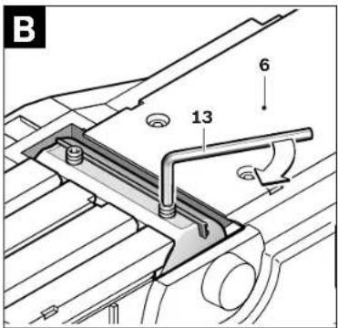
text_image
B 6 13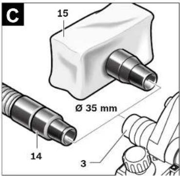
text_image
C 15 Ø 35 mm 14 3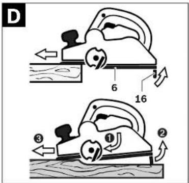
text_image
D 6 16 ① ② ③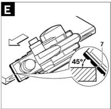
text_image
E 7 45°1 609 92A 2NH | (16.9.16) Bosch Power Tools


51

text_image
F 17 18 20 19 18 19 22 20 21
text_image
G 23 24
text_image
H 9 mm max 102 mm max


6|Deutsch
Deutsch
Sicherheitshinweise
Henk Becker Executive Vice President Engineering
Helmut Heinzelmann Head of Product Certification PT/ECS
Auss Bao i.v. H. W.
Robert Bosch Power Tools GmbH 70538 Stuttgart, GERMANY Stuttgart, 01.01.2017
Montage
General Power Tool Safety Warnings
WARNING
Read all safety warnings and all in-
structions. Failure to follow the warnings
and instructions may result in electric shock, fire and/or serious injury.
Save all warnings and instructions for future reference.
The term "power tool" in the warnings refers to your mains-operated (corded) power tool or battery-operated (cordless) power tool.
Work area safety
- Keep work area clean and well lit. Cluttered or dark areas invite accidents.
▶ Do not operate power tools in explosive atmospheres, such as in the presence of flammable liquids, gases or dust. Power tools create sparks which may ignite the dust or fumes. - Keep children and bystanders away while operating a power tool. Distractions can cause you to lose control.
Electrical safety
▶ Power tool plugs must match the outlet. Never modify the plug in any way. Do not use any adapter plugs with earthed (grounded) power tools. Unmodified plugs and matching outlets will reduce risk of electric shock.
▶ Avoid body contact with earthed or grounded surfaces, such as pipes, radiators, ranges and refrigerators. There is an increased risk of electric shock if your body is earthed or grounded.
▶ Do not expose power tools to rain or wet conditions. Water entering a power tool will increase the risk of electric shock.
▶ Do not abuse the cord. Never use the cord for carrying, pulling or unplugging the power tool. Keep cord away from heat, oil, sharp edges and moving parts. Damaged or entangled cords increase the risk of electric shock.
When operating a power tool outdoors, use an extension cord suitable for outdoor use. Use of a cord suitable for outdoor use reduces the risk of electric shock.
▶ If operating a power tool in a damp location is unavoidable, use a residual current device (RCD) protected supply. Use of an RCD reduces the risk of electric shock.
Personal safety
Stay alert, watch what you are doing and use common sense when operating a power tool. Do not use a power tool while you are tired or under the influence of drugs, alcohol or medication. A moment of inattention while operating power tools may result in serious personal injury.
▶ Use personal protective equipment. Always wear eye protection. Protective equipment such as dust mask, non-skid safety shoes, hard hat, or hearing protection used for appropriate conditions will reduce personal injuries.
▶ Prevent unintentional starting. Ensure the switch is in the off-position before connecting to power source and/or battery pack, picking up or carrying the tool. Carrying power tools with your finger on the switch or energising power tools that have the switch on invites accidents.
Remove any adjusting key or wrench before turning the power tool on. A wrench or a key left attached to a rotating part of the power tool may result in personal injury.
▶ Do not overreach. Keep proper footing and balance at all times. This enables better control of the power tool in unexpected situations.
▶ Dress properly. Do not wear loose clothing or jewellery. Keep your hair, clothing and gloves away from moving parts. Loose clothes, jewellery or long hair can be caught in moving parts.
If devices are provided for the connection of dust extraction and collection facilities, ensure these are connected and properly used. Use of dust collection can reduce dust-related hazards.

12 | English
Power tool use and care
▶ Do not force the power tool. Use the correct power tool for your application. The correct power tool will do the job better and safer at the rate for which it was designed.
▶ Do not use the power tool if the switch does not turn it on and off. Any power tool that cannot be controlled with the switch is dangerous and must be repaired.
▶ Disconnect the plug from the power source and/or the battery pack from the power tool before making any adjustments, changing accessories, or storing power tools. Such preventive safety measures reduce the risk of starting the power tool accidentally.
- Store idle power tools out of the reach of children and do not allow persons unfamiliar with the power tool or these instructions to operate the power tool. Power tools are dangerous in the hands of untrained users.
Maintain power tools. Check for misalignment or binding of moving parts, breakage of parts and any other condition that may affect the power tool's operation. If damaged, have the power tool repaired before use. Many accidents are caused by poorly maintained power tools.
- Keep cutting tools sharp and clean. Properly maintained cutting tools with sharp cutting edges are less likely to bind and are easier to control.
▶ Use the power tool, accessories and tool bits etc. in accordance with these instructions, taking into account the working conditions and the work to be performed. Use of the power tool for operations different from those intended could result in a hazardous situation.
Service
▶ Have your power tool serviced by a qualified repair person using only identical replacement parts. This will ensure that the safety of the power tool is maintained.
Planer Safety Rules
▶ Wait for the cutter to stop before setting the tool down. An exposed rotating cutter may engage the surface leading to possible loss of control and serious injury.
Hold the power tool by insulated gripping surfaces only, because the cutter may contact its own cord. Cutting a "live" wire may make exposed metal parts of the power tool "live" and could give the operator an electric shock.
▶ Use clamps or another practical way to secure and support the workpiece to a stable platform. Holding the work by your hand or against the body leaves it unstable and may lead to loss of control.
▶ Use suitable detectors to determine if utility lines are hidden in the work area or call the local utility company for assistance. Contact with electric lines can lead to fire and electric shock. Damaging a gas line can lead to explosion. Penetrating a water line causes property damage or may cause an electric shock.
▶ Do not reach into the chip ejector with your hands. They could be injured by rotating parts.
▶ Apply the machine to the workpiece only when switched on. Otherwise there is danger of kickback when the cutting tool jams in the workpiece.
1 609 92A 2NH | (16.9.16) Bosch Power Tools
▶ When working, always hold the planer in such a manner that the planer base plate faces flat on the workpiece. Otherwise the planer can become wedged and lead to injuries.
▶ Never plane over metal objects, nails or screws. The planer blade and the blade shaft can become damaged and lead to increased vibrations.
Products sold in GB only: Your product is fitted with a BS 1363/A approved electric plug with internal fuse (ASTA approved to BS 1362).
If the plug is not suitable for your socket outlets, it should be cut off and an appropriate plug fitted in its place by an authorised customer service agent. The replacement plug should have the same fuse rating as the original plug.
The severed plug must be disposed of to avoid a possible shock hazard and should never be inserted into a mains socket elsewhere.
Products sold in AUS and NZ only: Use a residual current device (RCD) with a rated residual current of 30 mA or less.
Product Description and Specifications

Read all safety warnings and all instructions. Failure to follow the warnings and instructions may result in electric shock, fire and/or serious injury.
While reading the operating instructions, unfold the graphics page for the machine and leave it open.
Intended Use
The machine is intended for planing of firmly supported wooden materials, such as beams and boards. It is also suitable for beveling edges and rebating.
Product Features
The numbering of the product features refers to the illustration of the machine on the graphics page.
2 Depth adjustment knob (insulated gripping surface)
1 Planing depth scale
3 Chip ejector
4 Lock-off button for On/Off switch
5 On/Off switch
6 Planer base plate
7 V-grooves
8 Handle (insulated gripping surface)
9 Blade drum
10 Clamping element for blade
11 Fastening screw for planer blade
12 Carbide blade (TC)
13 Hex key
14 Extraction hose (Ø 35 mm)*
15 Chip/dust bag*
16 Park rest
17 Parallel guide


English | 13
18 Scale for rebating width
19 Locking nut for adjustment of rebating width
20 Fastening bolt for parallel and beveling guide
21 Angle stop*
22 Locking nut for angle adjustment
23 Fastening bolt for rebating depth stop
24 Rebating depth stop*
*Accessories shown or described are not part of the standard delivery scope of the product. A complete overview of accessories can be found in our accessories program.
Technical Data
| Planer GHO 15-82 | ||
| Article number | 3601 E94 0.. | |
| Rated power input | W | 600 |
| Output power | W | 340 |
| No-load speed | min ^-1 | 16000 |
| Planing depth | mm 0 - 1.5 | |
| Rebating depth | mm 0 -9 | |
| Planing width, max. | mm 82 | |
| Weight according to EPTA-Procedure 01:2014 | kg 2.5 | |
| Protection class | ☐/II | |
The values given are valid for a nominal voltage [U] of 230 V. For different voltages and models for specific countries, these values can vary.
Noise/Vibration Information
Sound emission values determined according to EN 60745-2-14.
Typically the A-weighted noise levels of the product are: Sound pressure level 84 dB(A); Sound power level 95 dB(A). Uncertainty K=3 dB.
Wear hearing protection!
Vibration total values a_h (triax vector sum) and uncertainty K determined according to EN 60745: a_h=8m/s^2, K=1.5m/s^2
The vibration level given in this information sheet has been measured in accordance with a standardised test given in EN 60745 and may be used to compare one tool with another. It may be used for a preliminary assessment of exposure. The declared vibration emission level represents the main applications of the tool. However if the tool is used for different applications, with different accessories or insertion tools or is poorly maintained, the vibration emission may differ. This may significantly increase the exposure level over the total working period.
An estimation of the level of exposure to vibration should also take into account the times when the tool is switched off or when it is running but not actually doing the job. This may significantly reduce the exposure level over the total working period.
Identify additional safety measures to protect the operator from the effects of vibration such as: maintain the tool and the accessories, keep the hands warm, organisation of work patterns.
Declaration of Conformity CE
We declare under our sole responsibility that the product described under "Technical Data" is in conformity with all relevant provisions of the directives 2011/65/EU, 2014/30/EU, 2006/42/EC including their amendments and complies with the following standards: EN 60745-1, EN 60745-2-14, EN 50581.
Technical file (2006/42/EC) at:
Robert Bosch Power Tools GmbH, PT/ECS, 70538 Stuttgart, GERMANY
Henk Becker
Executive Vice President Engineering
Helmut Heinzelmann
Head of Product Certification PT/ECS
funk Seo i.v. h.m.
Robert Bosch Power Tools GmbH 70538 Stuttgart, GERMANY Stuttgart, 01.01.2017
Assembly
▶ Before any work on the machine itself, pull the mains plug.
Changing the Tool
▶ Be cautious when replacing the planer blades. Do not grasp the planer blades by the cutting edges. Possible danger of injury due to the sharp cutting edges of the planer blades.
Use only original Bosch carbide blades (TC).
The carbide blade (TC) has 2 cutting edges and can be reversed. When both cutting edges are dull, the planer blade 12 must be replaced. The carbide blade (TC) may not be resharpened.
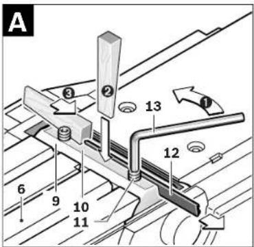
Disassembling the Planer Blade(s) (see figure A)
To reverse or replace the planer blade 12, rotate the blade drum 9 until it is parallel to the planer base plate 6.
- Loosen the two fastening screws 11 with the Hex key 13 by approx. 1–2 turns.
② If necessary, loosen the clamping element 10 by giving it a light blow with a suitable tool (e.g. a wooden wedge).
③ Push the planer blade 12 sidewards out of the blade drum 9 with a piece of wood.
Assembling the Planer Blade(s) (see figure B)
The guide groove of the planer blade always ensures continuous height adjustment when replacing or reversing it. If required, clean the blade seat in the clamping element 10 and the planer blade 12.
When assembling the planer blade, ensure that it is seated properly in the blade holder of the clamping element 10. The planer blade must be assembled and aligned centred to the planer base plate 6. Afterwards tighten the 2 fastening screws 11 with the Hex key 13.
Note: Before restarting, check if the fastening screws 11 are tightened well. Rotate the blade drum 9 by hand and ensure that the planer blade does not graze.
14| English
Dust/Chip Extraction
Dusts from materials such as lead-containing coatings, some wood types, minerals and metal can be harmful to one's health. Touching or breathing-in the dusts can cause allergic reactions and/or lead to respiratory infections of the user or bystanders.
Certain dusts, such as oak or beech dust, are considered as carcinogenic, especially in connection with wood-treatment additives (chromate, wood preservative). Materials containing asbestos may only be worked by specialists.
- As far as possible, use a dust extraction system suitable for the material.
- Provide for good ventilation of the working place.
- It is recommended to wear a P2 filter class respirator.
Observe the relevant regulations in your country for the materials to be worked.
Clean the chip ejector 3 regularly. Use a suitable tool (e.g., a piece of wood, compressed air, etc.) to clean a clogged chip ejector.
▶ Do not reach into the chip ejector with your hands. They could be injured by rotating parts.
To ensure optimum extraction of dust/chips, always work with external dust extraction or a chip/dust bag.
External Dust Extraction (see figure C)
Mount the vacuum hose 14 (accessory) on to the chip ejector 3.
Connect the vacuum hose 14 to a vacuum cleaner (accessory). An overview for connecting to various vacuum cleaners can be found at the end of this manual.
The vacuum cleaner must be suitable for the material being worked.
When vacuuming dry dust that is especially detrimental to health or carcinogenic, use a special vacuum cleaner.
Integrated Dust Extraction (see figure C)
A chip/dust bag (accessory) 15 can be used for smaller jobs. Insert the sleeve of the chip/dust bag firmly into the chip ejector 3. Empty the chip/dust bag 15 at regular intervals to maintain optimum dust collection.
Operation
Operating Modes
Adjusting the Planing Depth
With the adjustment knob 2, the planing depth can be adjusted variably from 0–1.5 mm using the planing depth scale 1 (scale graduation = 0.1 mm).
Park Rest (see figure D)
The park rest 16 allows the machine to be set down directly after operation, without danger of damaging the working surface or the planer blade. While planing, the park rest 16 is tilted upwards thus enabling full contact of the rear part of the planer base plate 6.
Note: The park rest 16 may not be removed.
Starting Operation
▶ Observe correct mains voltage! The voltage of the power source must agree with the voltage specified on the nameplate of the machine. Power tools marked with 230 V can also be operated with 220 V.
Switching On and Off
To save energy, only switch the power tool on when using it. To start the machine, first push the lock-off button for the On/Off switch 4 and then press the On/Off switch 5 and keep it pressed.
To switch off the machine, release the On/Off switch 5.
Note: For safety reasons, the On/Off switch 5 cannot be locked; it must remain pressed during the entire operation.
Working Advice
▶ Before any work on the machine itself, pull the mains plug.
Planing (see figure D)
Set the required planing depth and place the front part of the planer base plate 6 against the workpiece.
▶ Apply the machine to the workpiece only when switched on. Otherwise there is danger of kickback when the cutting tool jams in the workpiece.
Switch the machine on and guide the machine with even feed over the surface to be planed.
To achieve high-grade surfaces, work only with low feed and apply pressure on the centre of the planer base plate.
When machining hard materials (e.g. hardwood) as well as when utilising the maximum planer width, set only low planing depths and reduce planer feed, as required.
Excessive feed reduces the surface quality and can lead to rapid clogging of the chip ejector.
Only sharp blades achieve good cutting capacity and give the machine longer life.
The integrated park rest 16 also allows for continued planing at any given location on the workpiece after an interruption: - With the park rest folded down, place the machine on the location of the workpiece where the planing is to be continued.
- Switch on the machine.
- Apply the supporting pressure onto the front part of the planer base plate and slowly push the machine forward (①). This tilts the park rest upward (②) so that the rear part of the planer base plate faces on the workpiece again
- Guide the machine over the surface to be planed (③) with even feed.
Beveling Edges (see figure E)
The V-grooves in the front planer base plate allow quick and easy beveling of workpiece edges. Depending on required bevel width, use the corresponding V-groove. For this, place the planer with the V-groove onto the edge of the workpiece and guide it along the edge.
English | 15
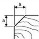
Groove to be used Dimension a (mm)
none 0 - 4
small 2 - 6
medium 4 -9
large 6 - 10
Planing with Parallel/Beveling Guide (see figures F-H)
Mount the parallel guide 17 or beveling guide 21 to the machine using the corresponding fastening bolt 20. Depending on the application, mount the rebating depth stop 24 with fastening bolt 23 to the machine.
Loosen the locking nut 19 and adjust the requested rebating width on the scale 18. Tighten the locking nut 19 again.
Adjust the requested rebating depth accordingly with the rebating depth stop 24.
Carry out the planing procedure several times until the requested rebating depth is reached. Guide the planer applying sideward supporting pressure.
Beveling with the Beveling Guide

When beveling rebates and surfaces, adjust the required slope angle with the angle adjustment 22.
Maintenance and Service
Maintenance and Cleaning
▶ Before any work on the machine itself, pull the mains plug.
▶ For safe and proper working, always keep the machine and ventilation slots clean.
Ensure easy operation of the park rest 16 and clean it regularly.
When the carbon brushes wear below acceptable service tolerances, the machine will automatically cut out. The machine must be sent to customer service for maintenance (for address, see the "After-sales Service and Application Service" section.
If the replacement of the supply cord is necessary, this has to be done by Bosch or an authorized Bosch service agent in order to avoid a safety hazard.
After-sales Service and Application Service
In all correspondence and spare parts order, please always include the 10-digit article number given on the type plate of the machine.
Our after-sales service responds to your questions concerning maintenance and repair of your product as well as spare parts. Exploded views and information on spare parts can also be found under:
www.bosch-pt.com
Bosch's application service team will gladly answer questions concerning our products and their accessories.
Great Britain
Robert Bosch Ltd. (B.S.C.)
P.O. Box 98
Broadwater Park
North Orbital Road
Denham
Uxbridge
UB 9 5HJ
At www.bosch-pt.co.uk you can order spare parts or arrange the collection of a product in need of servicing or repair.
Tel. Service: (0344) 7360109
E-Mail: boschservicecentre@bosch.com
Ireland
Origo Ltd.
Unit 23 Magna Drive
Magna Business Park
City West
Dublin 24
Tel. Service: (01) 4666700
Fax: (01) 4666888
Australia, New Zealand and Pacific Islands
Robert Bosch Australia Pty. Ltd.
Power Tools
Locked Bag 66
Clayton South VIC 3169
Customer Contact Center
Inside Australia:
Phone: (01300) 307044
Fax: (01300) 307045
Inside New Zealand
Phone: (0800) 543353
Fax: (0800) 428570
Outside AU and NZ:
Phone: +61 3 95415555
www.bosch.com.au
Republic of South Africa
Customer service
Hotline: (011) 6519600
Gauteng - BSC Service Centre
35 Roper Street, New Centre
Johannesburg
Tel.: (011) 4939375
Fax: (011) 4930126
E-Mail: bsctools@icon.co.za
KZN - BSC Service Centre
Unit E, Almar Centre
143 Crompton Street
Pinetown
Tel.: (031) 7012120
Fax: (031) 7012446
E-Mail: bsc.dur@za.bosch.com
Western Cape - BSC Service Centre
Democracy Way, Prosperity Park
Milnerton
Tel.: (021) 5512577
Fax:(021)5513223
E-Mail: bsc@zsd.co.za
Bosch Power Tools 1 609 92A 2NH | (16.9.16)


16|Français
Bosch Headquarters
Midrand, Gauteng
Tel.: (011) 6519600
Fax: (011) 6519880
E-Mail: rbsa-hq.pts@za.bosch.com
Disposal
The machine, accessories and packaging should be sorted for environmental-friendly recycling.
Do not dispose of power tools into household waste!
Only for EC countries:
According to the European Directive 2012/19/EU for Waste Electrical and Electronic Equipment and its implementation into national right, power tools that are no longer usable must be collected separately and disposed of in an environmentally correct manner.
Subject to change without notice.
Français
Executive Vice President
Engineering
Helmut Heinzelmann
Head of Product Certification
PT/ECS

i.v. h=mc
Robert Bosch Power Tools GmbH
70538 Stuttgart, GERMANY
Stuttgart, 01.01.2017
Montage
Robert Bosch (France) S.A.S.
Henk Becker Executive Vice President Engineering
Helmut Heinzelmann Head of Product Certification PT/ECS
juk Seo i.v. k.m.
Robert Bosch Power Tools GmbH 70538 Stuttgart, GERMANY Stuttgart, 01.01.2017
Montaje
Henk Becker Executive Vice President Engineering
Helmut Heinzelmann Head of Product Certification PT/ECS
if we see i.v. h.w.
Robert Bosch Power Tools GmbH 70538 Stuttgart, GERMANY Stuttgart, 01.01.2017
Montagem
- Antes de todos trabalhos na ferramenta eléctrica deverá puxar a ficha de rede da tomada.
Troca de ferramenta
Executive Vice President
Engineering
Helmut Heinzelmann
Head of Product Certification
PT/ECS
A## B## i.v. h:m
Robert Bosch Power Tools GmbH
70538 Stuttgart, GERMANY
Stuttgart, 01.01.2017
Montaggio
Executive Vice President
Head of Product Certification
Engineering
PT/ECS

i.v. h-m
Robert Bosch Power Tools GmbH
70538 Stuttgart, GERMANY
Stuttgart, 01.01.2017
40|Nederlands
Montage
Executive Vice President Engineering
Helmut Heinzelmann
Head of Product Certification PT/ECS

i.v. h=mc
Robert Bosch Power Tools GmbH
70538 Stuttgart, GERMANY
Stuttgart, 01.01.2017
Montering
Bosch Service Center
Telegrafvej 3
2750 Ballerup
På www.bosch-pt.dk kan der online bestilles reservedele eller oprettes en reparations ordre.
Tlf. Service Center: 44898855
Fax: 44898755
E-Mail: vaerktoej@dk.bosch.com
Bortskaffelse
Henk Becker Executive Vice President Engineering
Helmut Heinzelmann Head of Product Certification PT/ECS

Robert Bosch Power Tools GmbH 70538 Stuttgart, GERMANY Stuttgart, 01.01.2017
Montage
Bosch Service Center
Telegrafvej 3
2750 Balleru
Danmark
Tel.: (08) 7501820 (inom Sverige)
Fax: (011) 187691


Norsk | 51
Avfallshantering
Executive Vice President
Head of Product Certification
Engineering

i.v. k=mc
Robert Bosch Power Tools GmbH
70538 Stuttgart, GERMANY
Stuttgart, 01.01.2017
Montering
Executive Vice President
Engineering
Helmut Heinzelmann
Head of Product Certification
PT/ECS

i.v. h=m
Robert Bosch Power Tools GmbH
70538 Stuttgart, GERMANY
Stuttgart, 01.01.2017
58|Suomi
Asennus
Executive Vice President Engineering
Head of Product Certification PT/ECS

i.v. k=mc
Robert Bosch Power Tools GmbH 70538 Stuttgart, GERMANY Stuttgart, 01.01.2017
Συναρμολόγηση
Executive Vice President
Engineering
Helmut Heinzelmann
Head of Product Certification
PT/ECS

i.v. k=mc
Robert Bosch Power Tools GmbH
70538 Stuttgart, GERMANY
Stuttgart, 01.01.2017
Montaj
Bosch San. ve Tic. A.S.
Ahi Evran Cad. No:1 Kat:22
Polaris Plaza
80670 Maslak/Istanbul
Bosch Uzman Ekibi +90 (0212) 367 18 88
Işıklar LTD.ŞTİ.
Kizilay Cad. No: 16/C Seyhan
Adana
Tel.: 0322 3599710
Tel.: 0322 3591379
Executive Vice President Engineering
Helmut Heinzelmann
Head of Product Certification PT/ECS


Robert Bosch Power Tools GmbH
70538 Stuttgart, GERMANY
Stuttgart, 01.01.2017
Montaž
Robert Bosch Sp. z o.o.
Executive Vice President Engineering
Helmut Heinzelmann
Head of Product Certification PT/ECS

Robert Bosch Power Tools GmbH 70538 Stuttgart, GERMANY
Stuttgart, 01.01.2017
Montáž
Bosch Service Center PT
K Vápence 1621/16
692 01 Mikulov
Executive Vice President
Engineering
Helmut Heinzelmann
Head of Product Certification
PT/ECS

Robert Bosch Power Tools GmbH
70538 Stuttgart, GERMANY
Stuttgart, 01.01.2017


Slovensky|83
Montáž
Executive Vice President Engineering
Head of Product Certification PT/ECS
Executive Vice President Engineering
Helmut Heinzelmann
Head of Product Certification PT/ECS


Robert Bosch Power Tools GmbH
70538 Stuttgart, GERMANY Stuttgart, 01.01.2017
Сборка
OBJ_BUCH-865-007.book Page 97 Friday, September 16, 2016 11:40 AM
Русский|97
Казахстан
ТОО «Роберт Бош»
Executive Vice President Engineering
Helmut Heinzelmann
Head of Product Certification PT/ECS
A##B## i.v. H.W.C
Robert Bosch Power Tools GmbH 70538 Stuttgart, GERMANY Stuttgart, 01.01.2017
Монтаж
OBJ_BUCH-865-007.book Page 103 Friday, September 16, 2016 11:40 AM


Українська | 103
Україна
ТОВ «Роберт Бош»
Henk Becker Executive Vice President Engineering
Helmut Heinzelmann Head of Product Certification PT/ECS


Robert Bosch Power Tools GmbH 70538 Stuttgart, GERMANY Stuttgart, 01.01.2017
Жинау
OBJ_BUCH-865-007.book Page 109 Friday, September 16, 2016 11:40 AM
Казакша | 109
Executive Vice President Engineering
Helmut Heinzelmann
Head of Product Certification PT/ECS

i.v. h·w
Robert Bosch Power Tools GmbH
70538 Stuttgart, GERMANY Stuttgart, 01.01.2017
Montare
Tel. service scule electrice: (021) 4057540
Fax: (021) 4057566
E-Mail: infoBSC@ro.bosch.com
Henk Becker Executive Vice President Engineering
Helmut Heinzelmann Head of Product Certification PT/ECS
fws Sea i.v. h:m
Robert Bosch Power Tools GmbH 70538 Stuttgart, GERMANY Stuttgart, 01.01.2017
Монтиране
Executive Vice President Engineering
Helmut Heinzelmann
Head of Product Certification PT/ECS

i.v. k.m.
Robert Bosch Power Tools GmbH 70538 Stuttgart, GERMANY Stuttgart, 01.01.2017
Монтажа
Executive Vice President Engineering
Helmut Heinzelmann
Head of Product Certification PT/ECS

i.v. h·w—
Robert Bosch Power Tools GmbH
70538 Stuttgart, GERMANY
Stuttgart, 01.01.2017
Montaža
- Izvucite pre svih radova na električnom alatu mrežni utikač iz utičnice.
Promena alata
▶ Oprez pri promeni noževa rendea. Ne hvatajte noževe rendea za ivice sečiva. Možete se povrediti na oštre ivice sečiva.
Upotrebljavajte samo Original Bosch HM/TC-noževe za rende. Nož za rende od tvrdog metala (HM/TC) ima 2 sečiva i može se okretati. Ako su obe ivide sečiva tupe, mora se nož rendea 12 promeniti. HM/TC-Nož rendea se nesme oštriti.
Executive Vice President
Engineering
Helmut Heinzelmann
Head of Product Certification
PT/ECS

i.v. h=mc
Robert Bosch Power Tools GmbH
70538 Stuttgart, GERMANY
Stuttgart, 01.01.2017
Montaža
Henk Becker Executive Vice President Engineering Helmut Heinzelmann Head of Product Certification PT/ECS
funk Sea i.v. k.m.
Robert Bosch Power Tools GmbH 70538 Stuttgart, GERMANY Stuttgart, 01.01.2017
Montaža
Henk Becker Executive Vice President Engineering
Helmut Heinzelmann Head of Product Certification PT/ECS

Robert Bosch Power Tools GmbH 70538 Stuttgart, GERMANY Stuttgart, 01.01.2017
Montaaž
Executive Vice President
Engineering
Helmut Heinzelmann
Head of Product Certification
PT/ECS

i.v. h·w—
Robert Bosch Power Tools GmbH
70538 Stuttgart, GERMANY
Stuttgart, 01.01.2017


Latviešu|147
Montāža
Executive Vice President
Engineering
Helmut Heinzelmann
Head of Product Certification
PT/ECS

i.v. h=mc
Robert Bosch Power Tools GmbH
70538 Stuttgart, GERMANY
Stuttgart, 01.01.2017
Montavimas
Henk Becker
Senior Vice President
Engineering
Helmut Heinzelmann Head of Product Certification PT/ECS
Aur Beo i.v. h:m
Robert Bosch Power Tools GmbH, 70538 Stuttgart, GERMANY Stuttgart, 01.01.2017
التركيب
Henk Becker Senior Vice President Engineering
Helmut Heinzelmann Head of Product Certification PT/ECS

i.v. h=m
Robert Bosch Power Tools GmbH, 70538 Stuttgart, GERMANY Stuttgart, 01.01.2017
نصب
OBJ_BUCH-865-007.book Page 164 Friday, September 16, 2016 11:40 AM


164
1 608 132 006

1x: 2 608 635 376
2x: 2 608 635 350
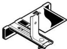
natural_image
Technical line drawing of a mechanical bracket or clamp assembly (no text or symbols)2 607 000 102
2 605 411 035
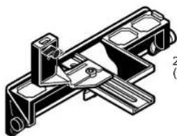
natural_image
Technical line drawing of a mechanical bracket assembly (no text or symbols)2 607 001 077 (45°)

2 605 438 532
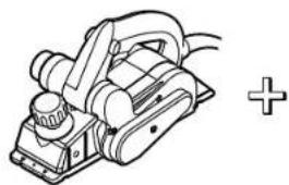
natural_image
Line drawing of a plow or saw machine with a plus sign, no text or symbols present


∅ 35 mm
3 m 2 609 390 392 5 m 2 609 390 393
GAS 25 GAS 50
GAS 50 M
1 609 92A 2NH | (16.9.16) Bosch Power Tools