GHO 700 Professional - Plane BOSCH - Free user manual and instructions
Find the device manual for free GHO 700 Professional BOSCH in PDF.

User questions about GHO 700 Professional BOSCH
0 question about this device. Answer the ones you know or ask your own.
Ask a new question about this device
Download the instructions for your Plane in PDF format for free! Find your manual GHO 700 Professional - BOSCH and take your electronic device back in hand. On this page are published all the documents necessary for the use of your device. GHO 700 Professional by BOSCH.
USER MANUAL GHO 700 Professional BOSCH
natural_image
Exterior view of a power tool with handle and control panel (no visible text or symbols)
Robert Bosch Power Tools GmbH
70538 Stuttgart
GERMANY
www.bosch-pt.com
1609 92A 4ZN (2019.09) 0/55

1 609 92A 4ZN
GHO 700 Professional

BOSCH
en Original instructions
fr Notice originale
pt Manual original
English ...... Page 7
Français ...... Page 14
text_image
A (12) (9) TC ② ① ③ (13) (14)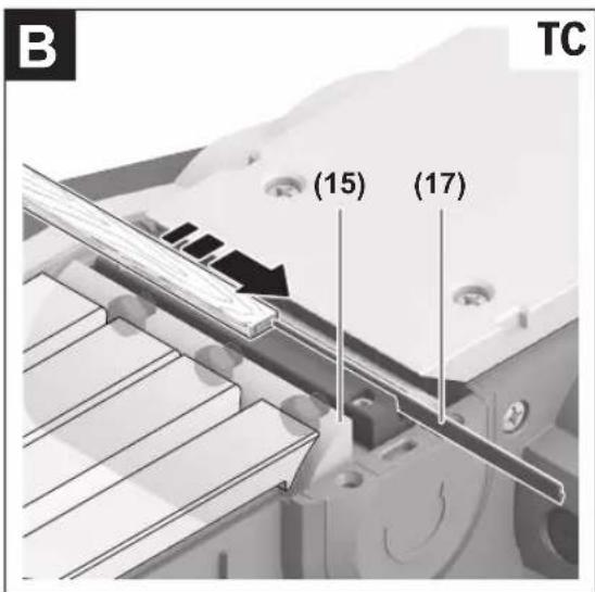
text_image
B TC (15) (17)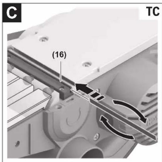
text_image
C (16) TC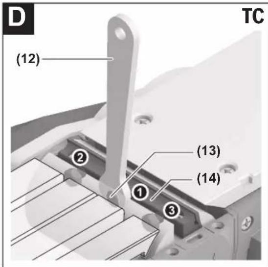
text_image
D (12) TC ② (13) ① (14) ③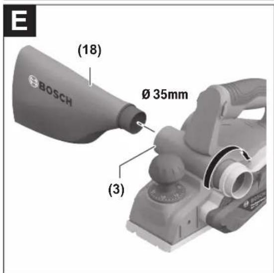
text_image
E (18) Ø 35mm (3)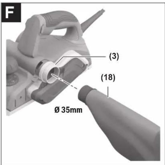
text_image
F (3) (18) Ø 35mm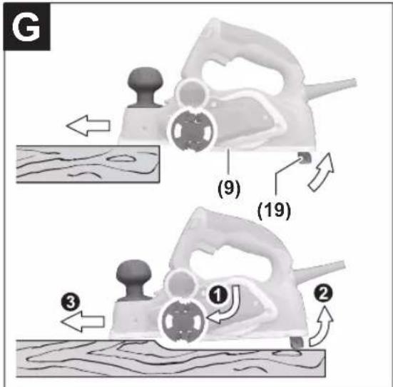
text_image
G (9) (19) ① ② ③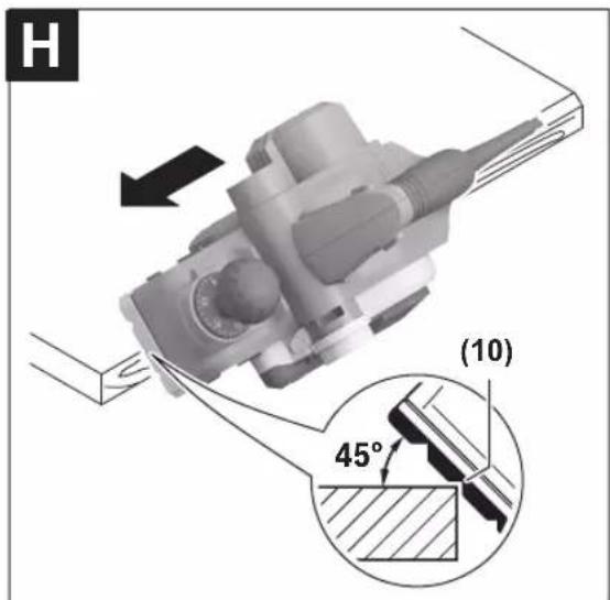
text_image
H (10) 45°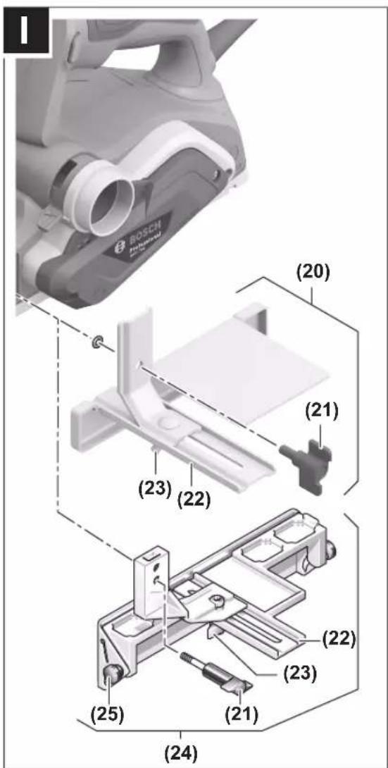
text_image
ROSCH (20) (21) (23) (22) (24) (25) (23) (22) (21)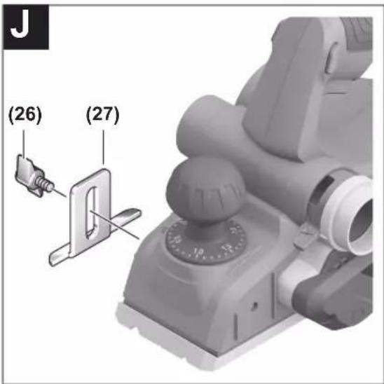
text_image
(26) (27)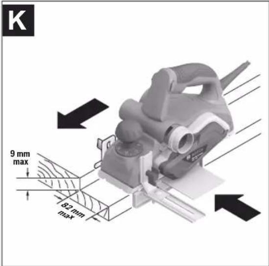
text_image
K 9 mm max 82 mm max6
text_image
(28) (6) (6) BOSCH PIONEER (7) (6)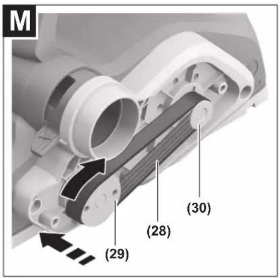
text_image
M (29) (28) (30)English
Safety instructions
General Power Tool Safety Warnings
WARNING
Read all safety warnings, instructions, illustrations and specifica-
tions provided with this power tool. Failure to follow all instructions listed below may result in electric shock, fire and/or serious injury.
Save all warnings and instructions for future reference.
The term "power tool" in the warnings refers to your mains-operated (corded) power tool or battery-operated (cordless) power tool.
Work area safety
▶ Keep work area clean and well lit. Cluttered or dark areas invite accidents.
▶ Do not operate power tools in explosive atmospheres, such as in the presence of flammable liquids, gases or dust. Power tools create sparks which may ignite the dust or fumes.
▶ Keep children and bystanders away while operating a power tool. Distractions can cause you to lose control.
Electrical safety
▶ Power tool plugs must match the outlet. Never modify the plug in any way. Do not use any adapter plugs with earthed (grounded) power tools. Unmodified plugs and matching outlets will reduce risk of electric shock.
▶ Avoid body contact with earthed or grounded surfaces, such as pipes, radiators, ranges and refrigerators. There is an increased risk of electric shock if your body is earthed or grounded.
▶ Do not expose power tools to rain or wet conditions. Water entering a power tool will increase the risk of electric shock.
▶ Do not abuse the cord. Never use the cord for carrying, pulling or unplugging the power tool. Keep cord away from heat, oil, sharp edges or moving parts.
Damaged or entangled cords increase the risk of electric shock.
▶ When operating a power tool outdoors, use an extension cord suitable for outdoor use. Use of a cord suitable for outdoor use reduces the risk of electric shock.
▶ If operating a power tool in a damp location is unavoidable, use a residual current device (RCD) protected supply. Use of an RCD reduces the risk of electric shock.
Personal safety
▶ Stay alert, watch what you are doing and use common sense when operating a power tool. Do not use a power tool while you are tired or under the influence of drugs, alcohol or medication. A moment of inatten-
tion while operating power tools may result in serious personal injury.
▶ Use personal protective equipment. Always wear eye protection. Protective equipment such as a dust mask, non-skid safety shoes, hard hat or hearing protection used for appropriate conditions will reduce personal injuries.
▶ Prevent unintentional starting. Ensure the switch is in the off-position before connecting to power source and/or battery pack, picking up or carrying the tool. Carrying power tools with your finger on the switch or energising power tools that have the switch on invites accidents.
Remove any adjusting key or wrench before turning the power tool on. A wrench or a key left attached to a rotating part of the power tool may result in personal injury.
▶ Do not overreach. Keep proper footing and balance at all times. This enables better control of the power tool in unexpected situations.
▶ Dress properly. Do not wear loose clothing or jewellery. Keep your hair and clothing away from moving parts. Loose clothes, jewellery or long hair can be caught in moving parts.
▶ If devices are provided for the connection of dust extraction and collection facilities, ensure these are connected and properly used. Use of dust collection can reduce dust-related hazards.
Do not let familiarity gained from frequent use of tools allow you to become complacent and ignore tool safety principles. A careless action can cause severe injury within a fraction of a second.
Power tool use and care
▶ Do not force the power tool. Use the correct power tool for your application. The correct power tool will do the job better and safer at the rate for which it was designed.
▶ Do not use the power tool if the switch does not turn it on and off. Any power tool that cannot be controlled with the switch is dangerous and must be repaired.
▶ Disconnect the plug from the power source and/or remove the battery pack, if detachable, from the power tool before making any adjustments, changing accessories, or storing power tools. Such preventive safety measures reduce the risk of starting the power tool accidentally.
▶ Store idle power tools out of the reach of children and do not allow persons unfamiliar with the power tool or these instructions to operate the power tool. Power tools are dangerous in the hands of untrained users.
- Maintain power tools and accessories. Check for misalignment or binding of moving parts, breakage of parts and any other condition that may affect the power tool's operation. If damaged, have the power tool repaired before use. Many accidents are caused by poorly maintained power tools.
8 | English
▶ Keep cutting tools sharp and clean. Properly maintained cutting tools with sharp cutting edges are less likely to bind and are easier to control.
▶ Use the power tool, accessories and tool bits etc. in accordance with these instructions, taking into account the working conditions and the work to be performed. Use of the power tool for operations different from those intended could result in a hazardous situation.
▶ Keep handles and grasping surfaces dry, clean and free from oil and grease. Slippery handles and grasping surfaces do not allow for safe handling and control of the tool in unexpected situations.
Service
▶ Have your power tool serviced by a qualified repair person using only identical replacement parts. This will ensure that the safety of the power tool is maintained.
Safety instructions for planers
▶ Wait for the cutter to stop before setting the tool down. An exposed rotating cutter may engage the surface leading to possible loss of control and serious injury.
▶ Hold the power tool by insulated gripping surfaces, because the cutter may contact its own cord. Cutting a "live" wire may make exposed metal parts of the power tool "live" and could give the operator an electric shock.
▶ Use clamps or another practical way to secure and support the workpiece to a stable platform. Holding the workpiece by your hand or against the body leaves it unstable and may lead to loss of control.
▶ Only bring the power tool into contact with the workpiece when switched on. Otherwise there is danger of kickback if the cutting tool jams in the workpiece.
▶ Do not allow the chip ejector to come into contact with your hands. You may be injured by rotating parts.
▶ Never plane over metal objects, nails or screws. Cutters and cutter shafts could become damaged and cause increased vibration.
▶ Use suitable detectors to determine if utility lines are hidden in the work area or call the local utility company for assistance. Contact with electric lines can lead to fire and electric shock. Damaging a gas line can lead to explosion. Penetrating a water line causes property damage or may cause an electric shock.
▶ While working, always hold the planer in such a way that the planer base plate lies flat against the workpiece. Otherwise the planer could slip and cause injury.
Your product is fitted with an BS 1363/A approved electric plug with internal fuse (ASTA approved to BS 1362).
If the plug is not suitable for your socket outlets, it should be cut off and an appropriate plug fitted in its place by an authorised customer service agent. The replacement plug should have the same fuse rating as the original plug.
The severed plug must be disposed of to avoid a possible shock hazard and should never be inserted into a mains socket elsewhere.
Products sold in GB only:
▶ Hold the power tool firmly with both hands and make sure you have a stable footing. The power tool can be more securely guided with both hands.
Product Description and Specifications

Read all the safety and general instructions.
Failure to observe the safety and general instructions may result in electric shock, fire and/or serious injury.
Please observe the illustrations at the beginning of this operating manual.
Intended use
The power tool is intended for planing wood-based materials such as beams and boards while resting firmly on the workpiece. It is also suitable for chamfering edges and for rebating.
Product features
The numbering of the product features refers to the diagram of the power tool on the graphics page.
(1) Cutting depth scale
(2) Knob for setting the cutting depth (insulated gripping surface)
(3) Chip ejector (either right or left)
(4) Lock-off button for on/off switch
(5) On/off switch
(6) Screw for belt cover
(7) Belt cover
(8) Changeover lever for chip ejector direction
(9) Planer base plate
(10) V-grooves
(11) Handle (insulated gripping surface)
(12) Open-ended spanner
(13) Fastening screw for clamping jaw
(14) Clamping jaw
(15) Blade head
(16) Guide groove for planer blade
(17) HM/TC planer blade ^A)
(18) Chip/dust bag ^4
(19) Parking rest
(20) Parallel guide
(21) Fastening screw for parallel/angle guide
(22) Scale for rebate width
(23) Locking nut for rebate width setting
(24) Angle guide ^A
(25) Locking nut for angle setting ^A)
(26) Fastening screw for rebate depth guide ^A
(27) Rebate depth guide ^A)
(28) Drive belt
(29) Large belt wheel
(30) Small belt wheel
A) Accessories shown or described are not included with the product as standard. You can find the complete selection of accessories in our accessories range.
Technical data
| Planer GHO 700 | ||
| Article number | 3 601 EA9 0.. | |
| Rated power input W 700 | ||
| No-load speed min | ^-1 | 16,500 |
| Cutting depth mm 0–2.6 | ||
| Rebate depth mm 0–9 | ||
| Max. planing width mm 82 | ||
| Weight according to EPTA-Procedure 01:2014 | kg 2.7 | |
| Protection class | /II | |
The specifications apply to a rated voltage [U] of 230 V. These specifications may vary at different voltages and in country-specific models.
Fitting
▶ Pull the plug out of the socket before carrying out any work on the power tool.
Planer Blade
Always change both planer blades – replacing just one blade will create an imbalance that could cause vibrations and shorten the service life of the power tool.
Changing the HM/TC Planer Blades
▶ Take care when changing the planer blade. Do not pick up the planer blade by the cutting edges. You may be injured by the sharp cutting edges.
Use only original Bosch HM/TC planer blades.
Hard metal (HM/TC) planer blades have two cutting edges and can be turned. If both cutting edges become blunt, the planer blades (17) need to be changed. HM/TC planer blades must not be resharpened.
Removing the Planer Blades (see figures A-B)
- To turn or replace the planer blades, turn the blade head (15) until the clamping jaw (14) is parallel with the planer base plate (9).
- Loosen the three fastening screws (13) using the open-ended spanner (12) (approx. 1–2 turns). The clamping jaw (14) does not need to be removed.
- Turn the blade head slightly and use a piece of wood to push the planer blade (17) to the side and out of the blade head (15).
- Turn the blade head 180^ and remove the second planer blade.
Fitting the Planer Blades (see figures C-D)
The guide groove on the planer blade ensures a constant, even height setting when changing or turning the blade. If necessary, clean the blade seat in the blade head (15) and the planer blade (17).
When fitting the planer blade, ensure that it is correctly seated in the mounting guide of the blade head (15).
The planer blade must be fitted and aligned with the centre of the planer base plate (9). Then tighten the three fastening screws (13) with the open-ended spanner (12). Ensure that the tightening sequence (①②③) on the clamping jaw (14) is followed correctly.
Note: Check that the fastening screws (13) are firmly tightened before start-up. Turn the blade head (15) by hand and ensure that the planer blades are not brushing against anything.
Dust/Chip Extraction
The dust from materials such as lead paint, some types of wood, minerals and metal can be harmful to human health. Touching or breathing in this dust can trigger allergic reactions and/or cause respiratory illnesses in the user or in people in the near vicinity.
Certain dusts, such as oak or beech dust, are classified as carcinogenic, especially in conjunction with wood treatment additives (chromate, wood preservative). Materials containing asbestos may only be machined by specialists.
- Use a dust extraction system that is suitable for the material wherever possible.
- Provide good ventilation at the workplace.
- It is advisable to wear a P2 filter class breathing mask.
The regulations on the material being machined that apply in the country of use must be observed.
- Avoid dust accumulation at the workplace. Dust can easily ignite.
Clean the chip ejector (3) regularly. Clean a clogged chip ejector using a suitable tool, e.g. a piece of wood, compressed air, etc.
▶ Do not allow the chip ejector to come into contact with your hands. You may be injured by rotating parts.
Always use an external dust extraction device or chip/dust bag to guarantee optimum suction.
Selectable chip ejector
Using the changeover lever (8), the chip ejector can be (3) adjusted to the right or left. Push the changeover lever (8) all the way towards the end position until it clicks into place. The selected chip ejector direction is indicated by an arrow symbol on the changeover lever (8).
Self-generated dust extraction (see figures E-F)
A chip/dust bag (accessory) (18) can be used for smaller jobs. Insert the dust bag nozzle of the chip/dust bag firmly into the chip ejector (3). Empty the chip/dust bag (18) at regular intervals to maintain optimum dust collection.
10 | English
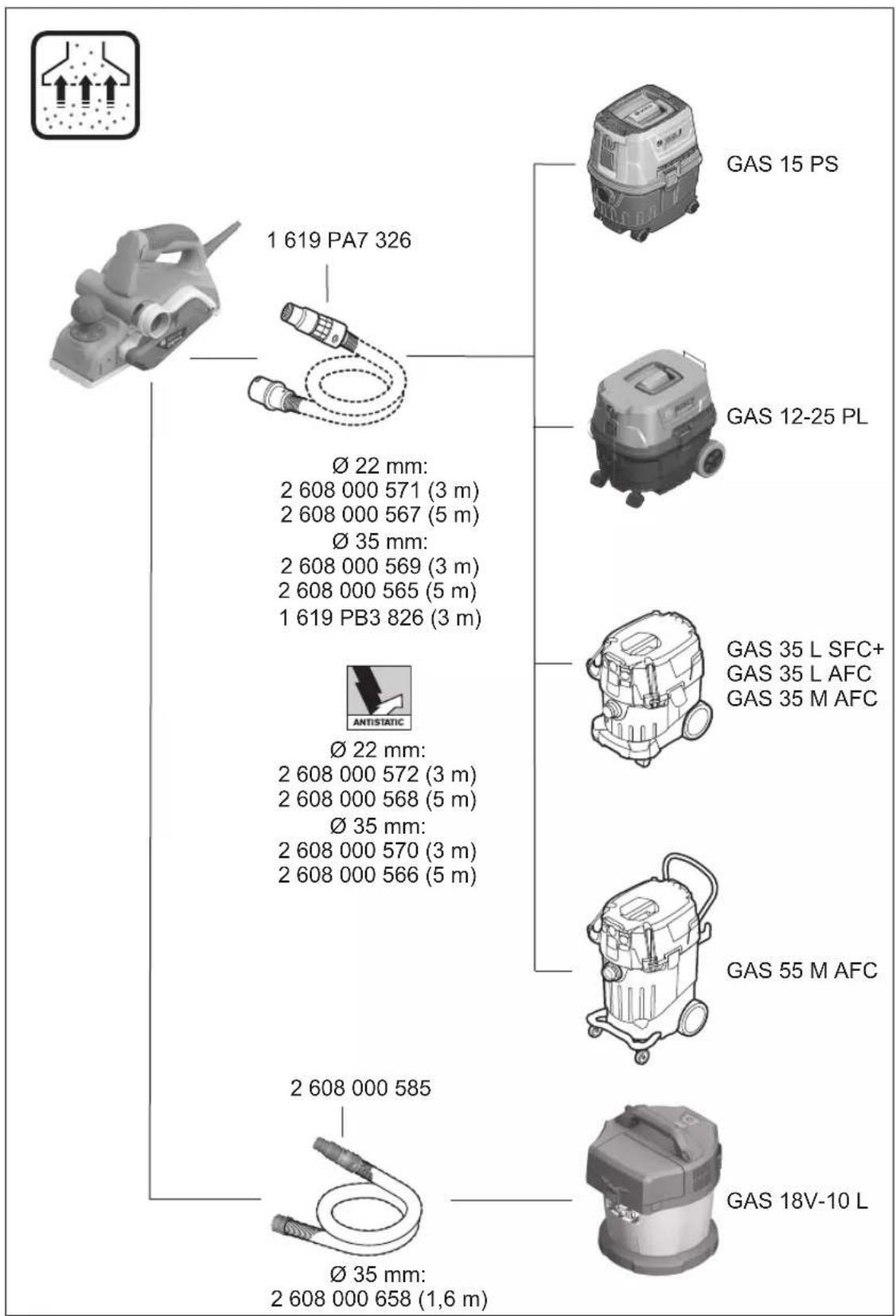
External Dust Extraction
An extraction hose (dia. 35 mm) (accessory) can be connected to the chip ejector on either side.
Connect the dust extraction hose to a dust extractor (accessory). You will find an overview of how to connect to various dust extractors at the end of these operating instructions.
The dust extractor must be suitable for the material being worked.
When extracting dust that is dry, especially detrimental to health or carcinogenic, use a special dust extractor.
Operation
Operating modes
Setting the cutting depth
Using the knob (2), the cutting depth can be continuously adjusted between 0–2.6 mm with the aid of the cutting depth scale (1) (scale division = 0.1 mm).
Parking Rest (see figure G)
The parking rest (19) makes it possible to put down the power tool directly after working, without any danger of damaging the workpiece or the planer blades. During the work process, the parking rest (19) is raised and the rear section of the planer base plate (9) is uncovered.
Start-up
▶ Pay attention to the mains voltage. The voltage of the power source must match the voltage specified on the rating plate of the power tool. Power tools marked with 230 V can also be operated with 220 V.
▶ Products that are only sold in AUS and NZ: Use a residual current device (RCD) with a nominal residual current of 30 mA or less.
Switching on/off
▶ Make sure that you are able to press the On/Off switch without releasing the handle.
To start the power tool, first press the lock-off switch (4), then press and hold the on/off switch (5).
To switch off the power tool, release the on/off switch (5).
Note: For safety reasons, the on/off switch (5) cannot be locked; it must remain pressed during the entire operation.
Practical advice
▶ Pull the plug out of the socket before carrying out any work on the power tool.
Planing Procedure (see figure G)
Set the required cutting depth and position the power tool with the front section of the planer base plate (9) on the workpiece.
▶ Only bring the power tool into contact with the workpiece when switched on. Otherwise there is danger of kickback if the cutting tool jams in the workpiece.
Switch on the power tool and guide it over the surface of the workpiece, applying uniform feed.
To achieve high-quality surfaces, apply only a low feed rate and exert pressure on the middle of the planer base plate.
For the processing of hard materials, such as hardwood, and also when utilising the maximum planing width, set only a low cutting depth and reduce the planer feed as appropriate.
Excessive feed reduces the quality of the surface finish and can lead to the chip ejector quickly becoming blocked.
Only sharp planer blades achieve good cutting performance and make the power tool last longer.
The integrated parking rest (19) also enables a continuation of the planing procedure following interruption at any point on the workpiece:
- Place the power tool – with parking rest folded down – onto the area of the workpiece that you will continue to work on.
- Switch the power tool on.
- Shift the contact pressure onto the front of the planer base plate and slowly slide the power tool forward (1). In doing so, the parking rest will swivel upwards and out of the way (2), meaning that the rear section of the planer base plate is in contact with the workpiece again.
- Guide the power tool over the surface of the workpiece, applying uniform feed (③).
Chamfering edges (see figure H)
The V-grooves in the front of the planer base plate enable quick and easy chamfering of workpiece edges. Select the V-groove that corresponds to your chamfering width. Then position the planer with the V-groove onto the edge of the workpiece and guide it along.
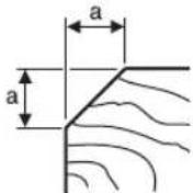
Groove used Dimension a (mm)
| None | 0-4 |
| Small | 2-6 |
| Medium | 4-9 |
| Large | 6-10 |
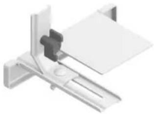
Planing with the Parallel/Angle Guide (see figures I-K)
Attach the parallel guide (20) or the angle guide (24) to the power tool with the fastening screw (21). Depending on the application, attach the rebate depth guide (27) to the power tool with the fastening screw (26).
Loosen the locking nut (23) and set the desired rebate width on the scale (22). Retighten the locking nut (23).
Set the desired rebate depth accordingly using the rebate depth guide (27).
Carry out the planing procedure several times until the desired rebate depth has been achieved. Guide the planer with sideways contact pressure.
Chamfering with angle guide
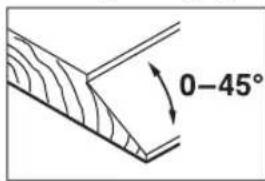
text_image
0-45°Use the angle setting (25) to set the necessary helix angle when chamfering grooves and surfaces.
Maintenance and Service
Maintenance and cleaning
▶ Pull the plug out of the socket before carrying out any work on the power tool.
▶ To ensure safe and efficient operation, always keep the power tool and the ventilation slots clean.
In order to avoid safety hazards, if the power supply cord needs to be replaced, this must be done by Bosch or by an after-sales service centre that is authorised to repair Bosch power tools.
Keep the parking rest (19) clear and clean it regularly.
When the carbon brushes are worn out, the power tool switches itself off. The power tool must be sent to the after-sales service for maintenance; see the "After-sales service and advice on using products" section for addresses.
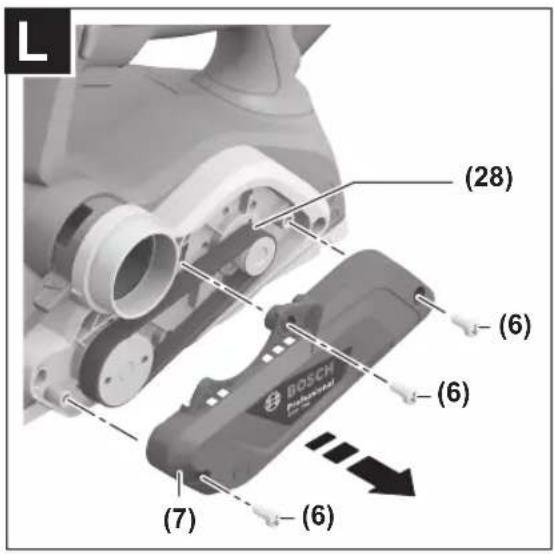
Changing the Drive Belt (see figures L-M)
Unscrew the screw (6) completely and take off the belt cover (7). Remove the worn drive belt (28).
Before fitting a new drive belt (28), clean the two belt wheels ((29) and (30)).
First place the new drive belt (28) onto the small drive wheel (30), and then press the drive belt (28) onto the large drive belt (29), turning it by hand.
Make sure that the drive belt (28) runs exactly in the length-ways grooves in the drive wheels ((29) and (30)).
Put the belt cover (7) on and tighten the screw (6).
After-Sales Service and Application Service
Our after-sales service responds to your questions concerning maintenance and repair of your product as well as spare parts. You can find explosion drawings and information on spare parts at: www.bosch-pt.com
The Bosch product use advice team will be happy to help you with any questions about our products and their accessories.
In all correspondence and spare parts orders, please always include the 10-digit article number given on the nameplate of the product.
Cambodia
Robert Bosch (Cambodia) Co., Ltd
Unit 8BC, GT Tower, 08th Floor, Street 169,
Czechoslovakia Blvd, Sangkat Veal Vong
Khan 7 Makara, Phnom Penh
VAT TIN: 100 169 511
Tel.: +855 23 900 685
Tel.: +855 23 900 660
www.bosch.com.kh
People's Republic of China
China Mainland
Bosch Power Tool (China) Co. Ltd.
Bosch Service Center
567, Bin Kang Road
Bin Kang District
Hangzhou, Zhejiang Province
China 310052
Tel.: (0571) 8887 5566 / 5588
Fax: (0571) 8887 6688 x 5566# / 5588#
E-Mail: bsc.hz@cn.bosch.com
www.bosch-pt.com.cn
HK and Macau Special Administrative Regions
Robert Bosch Co. Ltd.
Flat B, 2/F, Yeung Yiu Chung No. 6 Industrial Building,
19 Cheung Shun Street
Cheung Sha Wan
Kowloon, Hong Kong
Customer Service Hotline: +852 2101 0235
Fax: +852 2590 9762
E-Mail: info@hk.bosch.com
www.bosch-pt.com.hk
India
Bosch Service Center
69, Habibullah Road, (Next to PSBB School), T. Nagar
Chennai-600077
Phone: (044) 64561816
Bosch Service Center
18, Community Center
Phase 1, Mayapuri
New Delhi-110064
Phone: (011) 43166190
Indonesia
PT Robert Bosch
Palma Tower 10th Floor
Jalan RA Kartini II-S Kaveling 6
Pondok Pinang, Kebayoran Lama
Robert Bosch Middle East FZE - Pakistan Liaison Office
2nd Floor Plaza # 10, CCA Block, DHA Phase 5
Lahore, 54810
12 | English
Phone: +92(303)4444311
Email: Faisal.Khan@bosch.com
Philippines
Robert Bosch, Inc.
28th Floor Fort Legend Towers,
3rd Avenue corner 31st Street,
Fort Bonifacio, Global City,
1634 Taguig City
Tel.: (632) 8703871
Fax: (632) 8703870
www.bosch-pt.com.ph
Singapore
Powerwell Service Centre Ptd Ltd
Bosch Authorised Service Centre (Power Tools)
4012 Ang Mo Kio Ave 10, #01-02 TECHplace
Singapore 569628
Tel.: 6452 1770
Fax: 6452 1760
E-Mail: ask@powerwellsc.com
www.powerwellsc.com
www.bosch-pt.com.sg
Thailand
Robert Bosch Ltd.
FYI Center Tower 1, 5th Floor,
2525 Rama IV Road, Klongtoei,
Bangkok 10110
Tel.: 02 0128888
Fax: 02 0645802
www.bosch.co.th
Bosch Service – Training Centre
La Salle Tower Ground Floor Unit No.2
10/11 La Salle Moo 16
Srinakharin Road
Bangkaew, Bang Plee
Samutprakarn 10540
Tel.: 02 7587555
Fax: 02 7587525
Vietnam
Branch of Bosch Vietnam Co., Ltd in HCMC
14th floor, Deutsches Haus, 33 Le Duan
Ben Nghe Ward, District 1, Ho Chi Minh City
Tel.: (028) 6258 3690
Fax: (028) 6258 3692 - 6258 3694
Hotline: (028) 6250 8555
Email: tuvankhachhang-pt@vn.bosch.com
www.bosch-pt.com.vn
Bahrain
EA Juffali and Brothers for Technical Equipment Company.
Kingdom of Bahrain, Al Aker - Block 0624 - Road 2403 -
Building 0055D
Phone: +97317704537
Fax: +973177045257
Email: h.berjas@eajb.com.sa
Egypt
RBEG-LLC
22 Kamal Eldin Hussein
Sheraton Heliopolis
11799 Cairo
E-mail: boschegypt.powertools@eg.bosch.com
Iran
Robert Bosch Iran
3rd Floor, No 3, Maadiran Building
Aftab St., Khodami St., Vanak Sq.
Tehran 1994834571
Phone: +9821-86092057
Iraq
Sahba Technology Group
Al Muthana airport road
Baghdad
Phone Bagdad: +964 (0) 7 901 930366
Phone Dubai: +971 (0) 4 422 1898
Email: duraid@sahbatechnology.com
Jordan
Roots Arabia - Jordan
Al-Hurriyah Street, Al-Muqabalein
Amman 11623, Jordan
P.O. Box: 110068
Tel.: +962 6 4398990
E-mail: bosch@rootsjordan.com
Kuwait
Shuwaikh Industrial Area, Block 1, Plot 16, Street 3rd
P.O. Box 164 - Safat 13002
Phone: +965 - 2496 88 88
Fax: +965 - 2481 08 79
E-mail: josephkr@aaalmutawa.com
Lebanon
Tehini Hana & Co. S.A.R.L.
P.O. Box 90-449
Jdeideh 1202 2040
Dora-Beirut
Phone: +9611255211
Email: service-pt@tehini-hana.com
Libya
El Naser for Workshop Tools
Swanee Road, Alfalah Area
Tripoli
Phone: +218 21 4811184
Oman
Malatan Trading & Contracting LLC
P.O. Box 131, Ruwi, Muscat
Postal Code: 112, Sultanate of Oman
Phone: +968 2479 4035/4089/4901
Mob: +968-91315465
Fax: +968 2479 4058
E-Mail: sudhirkumar@malatan.net
Qatar
International Construction Solutions W L L
P. O. Box 51, Doha
Phone: +974 40065458
Fax: +974 4453 8585
Email: csd@icsdoha.com
Saudi Arabia
Juffali Technical Equipment Co. (JTECO)
P.O.Box: 1049 - Jeddah 21431 - KSA
Jeddah: 00966 (0) 12 692 0770 - Ext 433
Riyadh: 00966 (0) 11 409 3976 - Ext-30/34/39
Dammam: 00966 (0) 13 833 9565
E-mail: M.Zreik@eajb.com.sa
Syria
Dallal Establishment for Power Tools
Damascus. Baramkeh street - Ibn Amer street,
Phone: +963112241006 or 009631122414009
Mobile: 00963991141005
Email: rita.dallal@hotmail.com
United Arab Emirates
Central Motors & Equipment,
P.O. Box 26255, Dubai
Dubai: 00971 (0) 4 3090920/3090930
Abu Dhabi: 00971 (0) 2 4017745
Sharjah: 00971 (0) 6 5932777
Al Ain: 00971 (0) 3 7157419
E-Mail: Mallappa.Madari@centralmotors.ae
Yemen
Abu Alrejal Trading Corporation
P.O. Box: 17024, Zubeiry St.
Sana'a, Yemen
Tel: +967-1-20 20 10
Fax: +967-1-47 19 17
E-mail: tech-tools@abualrejal.com/yahya@abualrejal.com
Ethiopia
Forever plc
Kebele 2,754, BP 4806,
Addis Ababa
Phone: +251 111 560 600
Email: foreverplc@ethionet.et
Ghana
Robert Bosch Ghana Limited
21 Kofi Annan Road Airport Residential Area Accra
Tel. +233 (0)3027 94616
Kenya
Robert Bosch East Africa Ltd
Mpaka Road P.O. Box 856
00606 Nairobi
Nigeria
Robert Bosch Nigeria Ltd.
52-54 Isaac John Street P.O. Box
GRA Ikeja - Lagos
Tanzania
Diesel & Autoelectric Service Ltd.
117 Nyerere Rd., P.O. Box 70839
Vingunguti 12109, Dar Es Salaam
Phone: +255 222 861 793/794
Australia, New Zealand and Pacific Islands
Robert Bosch Australia Pty. Ltd.
Power Tools
Locked Bag 66
Clayton South VIC 3169
Customer Contact Center
Inside Australia:
Phone: (01300) 307044
Fax: (01300) 307045
Inside New Zealand:
Phone: (0800) 543353
Fax: (0800) 428570
Outside AU and NZ:
Phone: +61 3 95415555
www.bosch-pt.com.au
www.bosch-pt.co.nz
Republic of South Africa
Customer service
Hotline: (011) 6519600
Gauteng - BSC Service Centre
35 Roper Street, New Centre
Johannesburg
Tel.: (011) 4939375
Fax: (011) 4930126
E-Mail: bsctools@icon.co.za
KZN - BSC Service Centre
Unit E, Almar Centre
143 Crompton Street
Pinetown
Tel.: (031) 7012120
Fax: (031) 7012446
E-Mail: bsc.dur@za.bosch.com
Western Cape - BSC Service Centre
Democracy Way, Prosperity Park
Milnerton
Tel.: (021) 5512577
Fax: (021) 5513223
E-Mail: bsc@zsd.co.za
Bosch Headquarters
Midrand, Gauteng
Tel.: (011) 6519600
Fax: (011) 6519880
E-Mail: rbsa-hq.pts@za.bosch.com
Armenia, Azerbaijan, Georgia
Robert Bosch Ltd.
David Agmashenebeli ave. 61
0102 Tbilisi, Georgia
Tel.+995322510073
www.bosch.com
Kyrgyzstan, Mongolia, Tajikistan, Turkmenistan, Uzbekistan
TOO "Robert Bosch" Power Tools, After Sales Service
Muratbaev Ave., 180
050012, Almaty, Kazakhstan
Service Email: service.pt.ka@bosch.com
Official Website: www.bosch.com, www.bosch-pt.com
Disposal
The power tool, accessories and packaging should be recycled in an environmentally friendly manner.
14 | Français

Do not dispose of power tools along with household waste.
Français
Robert Bosch Morocco SARL
53, Rue Lieutenant Mahroud Mohamed
20300 Casablanca
Tel.: +212 5 29 31 43 27
E-Mail : sav.outillage@ma.bosch.com
Tunisie
Robert Bosch Tunisie SARL
Palma Tower 10th Floor
Jalan RA Kartini II-S Kaveling 6
Pondok Pinang, Kebayoran Lama
ال Ratings Impact: What is the correct.
Sahba Technology Group
شارع مطار المثنى
بقداد
Robert Bosch Morocco SARL
natural_image
Simple line drawing of a tool with a circular inset showing a folded edge (no text or symbols)2 607 000 096 (2x)
natural_image
3D rendering of a mechanical bracket assembly (no text or symbols visible)1 619 PB4 338
natural_image
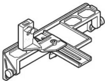
Technical line drawing of a mechanical bracket assembly (no text or symbols)2 607 001 077 (45°)

natural_image
3D rendered image of a gray Bosch-branded mechanical component (no text or symbols visible)1619 PB4 236